cosc
.~160PE~;Et\f~Cfl F'F~CkJECT
DEF't\F~H'1ENT OF CCI!"1PLITEF~ ~:;CIENCE UNIVEF~SITV OF CANTEPBUF~V.
Y HCHT IJESIGil.
Chapter
Page.
1. Jlf[f{DDLLCT I
QH
The Problem.Revievv· of other vvork with hull shape development. Current work in Ol1al~lsis of ~1acht hulls.
Dbjectivet~.
Fair lines.
Initial aims and objectives. Clltmges in oi ms ond obj eel i ves.
Final
airnt~ andobjectives.
The
standard representation.
Dio~]onols.Desi
~1n as on i ntui t.i ve process.By
hand.By
Computer.4..
ltJ
P L E t···t Erfr
t\
TLW:il)
E C l_gj..Qf_i;~1.
'7
J.
4.
5.
6.
7.
cl
10. 12. 12. 14. 15.
5. THE
_.LCU:lf?.1HIR
rtCJ12Il:
The need for a data model.
The requirements of the data model.
The basis for
u·,e
computer model. Description of Uw model used~\imp 1 i fi cations. Restrictions.
Ho'·l·l the rnor:Jel satisfies the requirements.
::;peed.
T lle alternative. con~:i dered.
The independencE! of the Sp 1 i ne routines.
The USt3r interface consistenq1.
Vo/i mlov·ts.
I would like to thonk rnq Dod Vv'llo qeve rne the interest ~ ~
em!
thebock~wound to be eble to do this project} eH·tcJ produced the designs use:~d in the testing process of the program at very short notice. Also I would like to tht:mk all those who kept me seme end fed while I worked through the
Jll'lHDDUC_TIDD
ThE1 problern being re!::earclled is that of hovv· cornputers can help in u·1e
dE1sign process thal is employed in designing a yacht hull. This is a
problern that has been reseerched before but with di fferenl results to
whet have bE,en achieved in this projE,ct. The main airns ~vere not to
provide fl true computer aided design program} but
a
useful set of toolsthat can . be used in the desiqn process. ~ .
The rnanual process for drewi ng up a set of curves to represent a hull is
a tedious process that often suffers frorn loss of accuracy on the dr-awing
boar·d. 1-\fter an initial st:1l of lines IHJS been drafted .. the process of
refinernent begins until the shape is acceptable to t11e designer. The final
stage of the design is to pEwfonn a sirnple analysis of the design .. usuallhl
in the fonn of a displacement apprm<irnation and a curve of area to
estimate the centre of di~•placernent from.
t\ny desi~1ner doing a thorou~11·1 job will rnake a detailed analysis of the
vveitlht that ~1oes into a boat to find thfl centre of mass of tlw boat. This is follovv·ecl by an accLwate as possible estimate of the centre of
clisplac,?.tnent of t11e boat and an effort to balance the centres of mass and
displacement. If this is not done the boat will not float on its dosigned
water line.
It is ver-~1 hard for the computer to help in the estimate of the rnass
tlwt goes into tht:1 boat without a great deal rnore infonnation than will be
·-considered ir1 Hli~; pr-oject. 'Where the cornputer can !Jelp is in the process of finclinq thE! disple1cernent e~ncl centre of clisplecernenl. This is not a tri viol process
to
perfonn
by hand~ as we 11 as being very i naccurote in most ceses. Using o suite1ble nurnet .. icel rneUwd~ the cornputer can rnake a mcwe eccurote est i rnotE! of these porornef.ers.REVIE\~1 OF UHlER \·'/llF~I< 11'1'ITIJ HULL SH;\F'E DEVELOPI·'1ENT. ---.. --~---~--,---··--·---·---~··-·---·---·-·---·--
~---·---·-·---·---~---t\ nurn!Jer of programs are comrnerci fl 11 y ovfl i 1 eb le for hu 11 shape
development. The best-known of these is ~John Letcher's Fflirline 2 and George Ht~zen's Faslyocht. [ 1
1
t\ 11
o
t
tJ1eseprograms o
llovv U1e
des i gnf3t" to deve 1 opo
hu 11 shepe in thecotnputer using relatively sirnple cornrnonds. " The sirnpler and less
e~wensive ones
ewe
not very well suitocl to rnore cornple~< sl1apes such as those you rnigl'lt wm1t to dr·e'N around thE! stem ofon
10~: ( lnternat.ionel Offslwre ~~oling ) boot or 1:1 12·-·l''let.rel while the more sopbisticated rmde)<pemd ve ones will hand! e just about any shape you rni ~lhl wont to
clravv
but often do so eJt. the e>(pense of requirin~l the us€H" to heJve doctoral€~ level rnetllernel i cs. " [ 1 J
Softwere is ovoilable in New Zeolond for hull design from ~1cDonnel Douglm::~ 1Nhich is advertised os ideel for· 3-Dimentdonol hull desi~w~~ os
well os colculoting the volumetric parameters and infornwtion used in the bui 1 cJi
ng
process.t\nother effort in tbis field was the invellwble project of I. T. Foster who inplementE!d e C;~D ( Computer 1~icled Design ) s~1stem for hull design. [2] The nwin drawbecks to the previous project were twofold. First wos
..-,
tl"'ot it 'vVas Lretc1·1 oriente ted os opposed to interflctive. This was because. of lwrdwore I i rnitCJti ons rot her then on~~thi ng else. The second drowtreck wes Hlflt the representation of the boet relied unpon e ::;et of curves that were totellly dis-sirnileH· frorn the stenderd views of the boet theit e designer is f mrli l i or will!.
There currently 8)';i~;t
o
nurnber of peckages otternpting to colculote verious pererneters of ~tocht hulls. The most cornmon forrn of colculotion perforrned on hulls is thot of ciisplocernent end centre of displecement. This rc~pre::;ents the rnost boring oncl leborious task~ as 'Nell es onE! that cen not be done very eccurotel~l try lwnd. Without this effort either bq
·-cornputer or by hend .. e boot buil det- connot be sure t11et t1 new boat wi 11
float on its proposed water line. The theoreticel wt~ter linE! is the line eround the hull thtit the wetEw corne::: to wllen the boot is ot rest in the vvot.er encJ not l1ee lee!. Tl1e boot is heeled wben it is l eeni ng to one side of vert. i co 1.
The ne)<:t logicol step is l"rydrostetic celculotions. An exornple of this is stability. To do o proper job~ oil hydrostatic CC!lculetions should be mede for e voriety of floetations) ond should take into eccount the feet thot e botlt spends o lot of its tirne not floating level but heeled on en engle.
t~fter the h~ldrostetic celculotions con·res the structural tlnerlysis. It is important for tbe designer to know how t11e llUII wi 11 trend end wlwre· t11e stresses crnd stn:rins ore upon the hull. This field is quite odvernced es o nurnbEn- of pockc1ges 8)\ist~: to perform the structurell enelysis on
orbitroril!:l cornple)~ sl-,ape~;. The type of analysis used for this is finite elernent analysis.
The next useful step it; colcult~tion of the rating of various hull shapes.
The
formulesare
t;pecificolly set up to focilitote the writing of relatively t•treight forwarci progromrnes. The re~ling of e~ boot is used for hondicop purposes so boots of different sizes and ratings cem roce E!Venlya~1 fJ ins t eoch otJ-1er.
The fined step is thot of perfornwnce predicition. This is the most cornplE!X port of yacht cletoi~Jtl At present lhe greotest use for perforrnonce pn:1diction is the cornporing of two clesigns. A lot of effort is being put into t11is field but to rnake ony kind of realistic prediction~ toclays
f3UF'ER
COI''lF'UTEF:~; need
lo
beu
li 1 i sed to handle t11e comp 1exitw
of the prob 1 ern.1~l pr-esent the current ~::oft
wore
rnoke o number of sirnplifications that cutbacll~l into the
occurocy
of the celculotions. The greatest use of the cutTent soft ware isin
cornpfJring
tl'leori t ica
1
desi ~1ns.Hopefully .. the sustem developed in this project will be eble to be used on ettdlrer-il~J complex shopes end yet still retoin the sarne procet•s tht~t o designer hos olwa~1s Ut:E!cl .. without t~ny specific knowledge of mothemotics bein£1 necest•tiry. The only fornilicwity useful is thol of the "stonclord" l"laci ntosl1 interface~ ·vvlli ell lws been uti 1 i zed.
ThE! targeted use for the project is to provide a tool for people clesiging smtlll racing dinghiE!S who m-e currently using Uw troditionel drafting boards end not getlinu around to doing ony forrn of displacernent analysis
lwcouse it is too hord ond tirne consuming or becouse tht::~y do not hove the knowledge necesser~1 to rnoke the enBlysis. t1eny of these people heve either e)<:isting boots or occess to existing boets thet cen be physice:Jll~!
weighed to find the mess cmd the centre of mas~:. Having
e
boet thet does not floaton
its proposed Yv'etet- line is the dinghy designers greatest feult.The concept of e feir set of lines is introduced here os it is referred to throughout the report. A line is seid to bt:1 foir when it is
e
srnooth curve ond r:ontoins no bumps or hollows. A curve is usuelly feir when there is nochan~w of si~1n in t11e second derivotive of the curve. It is usually the det:i gners goe~l to produce
e
f oir
set of curves. EXC!trlp 1 es of fBir end
non felir curves ewe included leler in the report.Tlw initial aims of u·,e project were to irnplernent B suiteJble dota rnodel to represent
a
boat on o cornputer end perform en anel!dSis of this model.The onol~jsis \·Yfls to consist of hYo seperete pBrts. First WF.JS EJ
~Jt"Bphical EJIH:'Il~!sis of t11e
hun
in tbe form of o set of lines dreiwnby
the computer. The set of line~; ore the stonderd vvoy o boet is reprE!sented on o cornputer. The lines ore u::;edby
the designer to obtBin an ideo of tile~dH:Jpe of
u·,e
boot oncl to see if the boot is f ei r.Tl-,e secoml 1NDS for the computer to perform sorne simple colculetions
on
thehull
to ol:ltoi n o nurn!Jer ofpc1rorneters.
The peJrernetersore
neededI
to find
ifthe
hull rneets the requirernents the designer has chosE!Il Themost
irnportent parorneter tllat
e cornputer could calculate isthe
displEJcernent of the boat.
,\fter the cornputer rnodel for the boat and part of the graphical output of the de:::;ign vvere irnplemented on the PI~ 1 1'1E in the fin:;t term, a problem arose when examining the plots produced as EJ results of testing the model
on a si rnp I e design. TheSE! prob I erns caused some change in objectives to be rnade.
Th£1 protJ I E!ln 1Nas to do with the choice of data points to reprE,sent tl"le
shape of the hull.
By
a bad choice of points the following frarne for a boat was obtained.0 200 400 600
0. ---t-·f-·--t--+--1-+ -l
200- .
[image:11.595.177.436.368.564.2]400-~---~~---·111··"-11! ... _
figure 1. An 'unfair' curve.
Exornple of a frame with badly chosen data points.
vv'hen atternpts were
rnade
to correct these curvesby
choosingdifferent data points it vv·as found to be impossible to choose the clata points correctly by changin£1 the numtJers that represented the points.
Tllen1 were man~t problems. First was the turn around
tirne
fromediting
the
data points ina
fileto
receiving the plots that represented tilecurves. Tl'ds tirne vv·as nE!Elr an hour if thE! plots could be retrieved i rnrnecli ate l ~I after printing.
The second ~vas the irnpossillility of manipulating the sl"lape of a t1oat as a set of nurntlers ond still rnaintaining somEl ideo of tile sl"lopE~ H1at was being procluced. 1\fter thE! data had been changed a srnall number of tirnes~
the twll was no longer the sarne st·,ape as t11e planned shape and if thE~
process had continued furt1·1er, a detailed analy~;is of sorne diffc~rent hull shape could have been performed.
The result of the testin~t W8~; u·,e idea thst
a
set of numbers is notan
acceptable way to repn~srmt a boat when a human has to rnanupi late the shape of tb£J
boat. Thti
onl~J time thata
set of numbers isan
acceptable method, i~; for interfacin~J between various places like a plan anda
pt1ysical set of frarnes, or for entry of an m<isting design.
·n1c1 fined
oirn of
Hle proJect i~; to pr-oduce a suitatde system for rnani pul ali ng tllCl shope of yacht t·1ull s H1at can be used as a basis for theinitial analysis. Using tt-Jis basis, a design could be entered into the systern, the ~;hsp8 rnsnipulated until it is as required, then analysed. t\fter
the sns lysis, U1e shape of tile hull can be changed for further ana 1 ysi s without leaving the cornputer.
Tl1is rneans the objecti'v'EJ is now to produce an interactive Computer AiciE:1d Design (CAD) sy~;tern tl'lat maintains eittler the original data rnodel ..
or- s cornpatab le data rnodel.
The CI\D systern needs to be able to enter an initial design, show the
design on the ~:crem·1 EJnd interactivly rnanipulate
u-1e
shape of the de£>ignuntll the designer is satisfied vvith it. The following is the sante frame as
in tl"le previous exrnple, e)<cept that it has been res!"Japed
using
sucha
systern.
0 200 400 600
0-- -t-+--t-1---1---+-
1-fi~1u1-e 2. I\ feir
frame.
The same frame 1Nith the date~ points moved sligllt.ly.
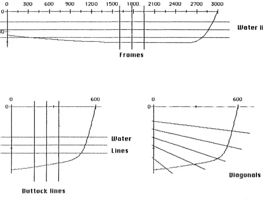
Tile universally accepted rnethocl of pictorially representing a yacht
hull i~; given by a set of lin8.2 .. " [2] Ttw lines are different views of the
same bull slwpe. For each vi e'vv, a nurnber of paralle I s I ices aro taken
througl1 the hull, and the view consists of the lines of intersection. Three
main views are usually used to represent the shape of the boat for visual
analy.sis. These ere the frames, the water lines and
u·1e
buttock lines.Often a fourth set of lint1s called tliE:~ diagonals are also generated as an
appro~~irnation of a vievv of the boot when it is heeling. The di8£JOnals are at different angles to approximate different angles of heel. 1~n e>wrnple of
a set of lines cJravvn by hand is given in opendi >< A.
The lines are used to uniquely define the shapo of the hull in
3-Dimensions. From the lines the hull attributes can be calculated. The
final step in the design process is to toke rneasurernents off the lines to
serve as data for the builder of the hull. The measurernents taken off are
called offsets. It is the aim of the designer to produce the set of lines.
The final property the lines rnust have is they must be consistent. The
lines are consistent 'v'v'hen all pairs of lines in 2-Dimensiom: define the
sarne shape in 3-Dirninsions.
0 300 600 900 1200 1500 H 00.
---t--1--t--t-t-+--+--+
--•--t-
f+-1·--·
-"'----~-0 600
--~----~
IJuttock lines
--
-
~---Frornes
·- UJoter
Lines
2100 2400 2700 3000
I I f - I
I
I
/
_,_/
()
0--·-~~ ·
-figure 3. The cuts to genenJ te ltle different views.
Water lines
600
[image:15.597.24.553.97.534.2]For the purpose of this pr·oject} the diagonals are not considered
i rnportant. The reason for t11i s is that the di egonals only give the designer
a vague i cJeo of the siH:tpe of the boat when it is 11E,el i ng. As a yacht actuall~l spends all of its tirne heeling vvhen it is seiling} it would be far
more useful to heel tilE! boat and redraw all three of the rnain vievvs again.
This would give an occurate picture of the shape of the boat lwll as it
passes through the water} as opposed to just an appro)dtnation.
Unfortunatel~l,. the heeling of the boat and the subsquent reclra'lving of the
lines .is outside the scope of this project.
Designing
a
boat is far rnore of on intuitive procE!~:s relying on theskills of thE! designer then u scientific process following set forrnula. The
designer U8lwlly works within
a
frornework of requirements.Given the same set. of requirements no f.\.vo designers will produce tt"Je
sotllE' desi9n. Both designs vvill be fair, both will meet the requirernents
end both will be very different. Cine of the two designs twill perform
better than the other but neiU'wr will be optirnol. Frorn onE! ~:et of
requirernents e cornputer will onl~t produce one desi~Jn1 removing the
creative differences of the hurnen designers.
Initial Requirements eg Length,
Width ..
·--1·---rr: ·-·--·-- ---
c
-·--J-aw~~~ o~ i ne~ ~---····-·---·-·---
-_______ I ____
J
Analysis of Fairness Not Fair
Visual ~-ppraisal
---Not
u-,;;h~~ir;d--Mol<e o change to one of the views, staying inside the initial requirements.
G
.
Calculate~a~ameters ~·
Do!!<.£ not utidyPK.am~t!l<r£.
g Centre of Displacement ·
-Draw a final Set of Unes
-Calculate a Set
ofOffsets
for Building Information
The most notable tiling about the design process by hand is tlwt it is
ver~1 slow. The tirne token to ckaw the example set of lines in eJpendix t\
was over four hours. The exornple hull ~diope is o very simplified cese tiS il hml no initio! requirernents oncl no porarneters to satisfy. The time
token 1Nos in tl"le drowing end fairing process. To ensure tllot the different
views were consistent .. onl~l care end excellent drafting ebilit.ief• wet·e needed. Ensuring consistency it: not o triol ond error process es is sornetirnes thought.
I
2 JThe process usee! to orive at
o
finell cle~:ign i~: an iteretive process ofessentioll~l clrm·ving the vie1N$ emd evulating tlwrn. Vv'hen changes orE! rnt~de
to the vie'NS, the~1 are usuoll~l mode in sucl1 o fashion thot the design stays \Yithin the initinl I"EHJUirernE!nts. It is not difficult to keep o hull tit fJ fixed lt~ngtll when ci10n£1ing tile shnpe of i l.
Or1e of the prol:tlerr1s with the droflinu process it: o loss of detf.li 1 f.lnd the ecclweqJ being limited bkl t11e drofting skills of the designer. This cen leod to the fintll shape of the hull otter building, not being vVhtlt thE:~
(Jesigner vvtmted. If U1is heppens, it is every difficult process to change the shope of the hull to wiH'It tlw designer thought the design represented.
The second port of the evoluelion involving the colculotion of the simpler pore11r1eters like clisplocernent is often neglected os it is beyond the de:::i ~1ner skills.
T lie place that tilE! skilled desi ~1ner is neecled is in the vi sut~ 1 apprai so 1 of the desi~Jtl As no dit·ect coclulations exists to get the best possible desi ~1n, it is up to t11e desi uners intuition to rnoke design the best possi b 1 o hull shepe for the requirernents.
The cornputer should never cl1tmge the siH:'lpe of the boet
by
itself. All clwnges should be mode onl~l b~l the control of the designer. This is beceuse there are too rnen~1 veriatdes for the cornputer to deal with in boet design. Some work is now being clone on cornputet~ generated designs, onsuper- computers, but os ~tel is not ver~1 successful.
To
be useful inU1e
design process, the cornputer needs tobe
oble to do the following thin~r:::1.
Inputon
i ni lio
1 hull
slwpe.2. t-Joc.li
fy
the hull shope.5. Drovv the different views of the hull.
4.
C:elculotetlie
required
porometers
ofthe
hull.If the~ computer con do o 11 of the above, it would si rnp 1 i
fy
ond speed the design process up. The rest of tl1e report is cleo 1 i ng with how the computer con be us eel to aci-d eve the above.Ch.optl.'r 4.
I
UlP._LI;_lllEltiHJ
IOJl_DJ~C1S
I
DUS
Tile most fundornE!I"Itol requirement is that the computer preserve the some process of designing tile hull. The use of the computer is in sirnlifhling and speeding up the different step~; in the process. The computer should also be copoble of gr·et~ter· occuroq1 w·llicll \·\"ill t.llso help to improve the desi{ln process.
The ideas for the btlsis of the CAD system come from o ~·1e1cintosh
opplicolion, 1''1e,cDrow. The ideo frorn 1''1ocDra'tv wos to be oble to selE!Ct o curvE!, end retJn:~pe the curve. V/llen o curve is selected in t'1acDrow, the points defining the curve are hi[lhlighted. The cur·ve is resheped by
dro~Will£1 one of the points defining the curve with the rnouse, ond rednnvin£1 the new curve IJS the rnouse rnovecl.
From the abovo comE! Uw ide a of se 1 ecti ng a frarne end n:.~shapi ng the frorne interoctivly with U113 nwus€1.
Tile
otiH:n· required feolun~ wosto
be eble to hove multiple vic~ws of thehull shape. The eli ff erent views from eli ff erent eli rt1ct ions ore requi reel to enotd e the (iesi gner to vi suo
1
i ze the shape of t11e hull in 3-Di mensi ons. I dealy
each view would remain consistent \·Vi th eoch other~ a I 1 updating when a change was rnelle tu any of then1.Tlws tile feotures required for the planned CAD systern are a mouse, and some
woy
to irnple.rnent rnultiple groplliced views.Frorn tl-18 r8quirt!d features carne to pl1ysical requirements, one a mouse, tile other is some forrn of graphics device. As it is not necessary
to !JSV8 all vi8YVs pre~a:mt at once, or indeed to t"lavB more than one vif~W at a time, a sin~J]e graphics window could be used on the screon.
The initial !-lope was to use
o
t'1acintosh as an intelligent graphics terrninal ami continue working on the PR 11"1E. 1\ prograrn called the Griffin Terrninal e)<ists that runson
t1"1e t·'tacintosh tbat emulates a graphics tN·minal, but it clicl not 11a'v'e 'fJ cornpetable baud rate to the network thatthe F'RH'1E is connected to. The rnain problern vvith using a t"tacintosh as an intelliqent terrninal WElt: the speml that data could be sent to Uw terrninal.
To
draw 8 curve a~:a
~:et of pointson
the screen at rnm~irnun resolutionwould takE!
( 512 pixoles ·)\· 2 x,y
*
16 hH illto?gen: )I
4cWO baud :: 3.4 sec.This tirne is slow for an interactive systern, and fn~quentlu 1r1UC:h more elate tbsn one curve is sent to the screen.
The final (Jecit;ion wo~: to irnplernent the Ct\D systern on tbe t'lacintosh
itself
wt·lich couldsupport
rnultiple windows for the multiple views, andhac! t11e e)<:cf~llent graphic routine~; of Quick Draw available, as well as an
i
ntegn.1
1 llwuse.Cine of the protderns 'vVitb the t·'tacintosh is that compiled applications
for the t·'Jecintosl·l can not tJE, writen on tile t·'tocinto::JL Tl·1e two cornputers
available to 'v'vTit£1 t11e progrsm on wen1 th~1 departmental VA>( or the Lisa.
The Lisa vvas chosm1 a::: it supported an Object orientated Pa:::cal ttased I snuuage, ami a pack 8gB ca II ed t·'tacApp that i ::: used to :::i rnpl
ify
window andrnenu maintenance.
For the Clilllput er to IJo atd
e
to perf onn ony useful function in the clesi gnor
analysis process it must l1ave some internal representation of thet1ull
shape. The prirnorll function of tlw computer then is to maintain J analyse
and rnanupilate this rnodel.
1-\s the proces~: of ~1ocllt de~:ign is
a
geornetric protdernJ no ~:itr1plecornputer data structurc,s: exist that n:dlect the structure of the problem. HenCE! sorne specific dt:Jta structure rnust be used to represent the shape of
tlw hu I l.
For the rnodel to bo itnplernented on the t"lacintosh for interoctive graphics~ it rnust bE! cornpoct os: tile t·'locintosh I"Jf1S very lirnited disc and rru::~rnory shape~ and rnust be capable of bei
ny
quickly evaluated and updated.The ~:irnplBst rnoclel vvoulcl tw EJ s:et of points in three dirn£msiom: but to
have any kind of accuracy tl"'e arnount of data would be prohibitive. Thus
somE! morE! complel<: model to represent the hull sl"1ape on the computer is
required.
The follovving is a list of the requirrnE,nts that have been found as necossary for u·1e rnodel.
1. ThE' modE!! rnust be space efficient. The reasons for this are Uwt the model rnust be implemented on sorne srna
11
cornputer and rnust be rnanupi1
a
ted in real t i rne.2. The rnodel must be able to be evaluated quickl~l·
this is for two reasons. Firstly the calculation of the curves is ·to be interactive and hence the points
on
the curve rnust be atrle to btl foundquickl~l· ~:;econdly.. an~! form of pararneter
calculation on the hull is going to involve
a
large nurnbor of Bvaluations of different points on the lwll.3. The rnodel rnust be able to bE1 evaluated at any
cliscrBet point on the surfece of the hull. This is again for parmneter calculation such as cl i sp
1
aCE! rnen t.,4. The modtd must be capable of representing any hull shope. It would l~1e rnuch better to have
a
model that could ropresent all hull shapes rather thans
t;rnall subset of tbe possi b 1 e siHlpes.
:;. The modnl rnust be easily rnodified. This is so thE.~
interactive pert of tht1 progrern con ch8nQE:1 the shape of the boat and not hove to wait
a
prohil)itive len£}tl"l of tirne before being atde to
examine tho result of the chan~1es.
A clesiu1wr should be able to rnanipulate the shapE.~
of the boat ond bave psrorneters calculated for the boot vvithout knowing how tho boat is represE,nted in tlw cotnput er.
7. It rnusl be feosibli;l to rJut
a
user intEwface upon the model. The in te1'·r ace need not supp 1y
thesame
rE,presentotion as the~ intBtTJCil representation. Tl"le
rnoi
n requi rernent of the representoti on to the end user isu-,at
it conve~1sell
the inforrnationthat
the traditional views of the hull convey. The simplest way toclo tllis
would to have llle traditional view osthe
repre~;entationto u-,e
user.8. The modo! rrnwt be suitablo as a llasis for furu-,er
ono1~1sis like structurcJ! analysis using finite e 1 ernent ana 1 ysi·s.
NOTE ll is
not
thought thot the rnodel should autornatical 1~1 enforceand produce fair lines for tho hull shope. Given the full set of views of the boat) it is not a hard process for the dE1signer to fair the lines as requirBd. Often in modern boots there
are
bumps and flats on the hull forrating
purposes that are not considert~d fair, but are considered an overall advantogE' V'l't-Jen the rating is taken into account.
other reasons for not hovi
ng
the cornputer model produce fair I i nes is the inherent problem of cl8fining exactly what is o fair set of lines. In some coses different dc1signers do not consiciE'r the sarne set of lines as fair) so it falls on the desi~1ners opinion as to what is fair and what is not.Finally) it rnust bE' kept in mind tt·1al the desi£1t18rs final airn is usually to ~~roduce a fair shape that satisfies U1e initial requirmEJnts. Hence it must not onl!d be possible to ~~~-oducE' fair lines) but also eas~1.
In reality man~t thousands of points would tte needed to accuretly dE,fine the shape of
a
IJoat11u11,
or some cornplex whole surface equotions vvilh mon~1 coefficients couhJ be used. The oclual rnodel used takes the real building process into account and uses VBry few points to dEifine the shape of the boots hull.\v'hen a boat is built, onlq a small number of points or offsets are used . ~ to define the frames. Tl1ese points ore srnooU1ec.J by bending flexible battons or splines around the points to give the final shape of the frarnE!.
A srnall nurnber of these frarnes are t11en usec.J to define the 3 dirnensional shapE1 of the boat. To decrease ti1E~ nunber of frarnet: necessary at the front
of the boat to clefine the profile cw stern .. a separately shopecJ keel is often
includE~d. CIVE!r the fronws planks of woocl ore bent, again gi'v'ing the shape of spline curvE~s. Thi~; process is even used when building rnodern boats out of fibreglass and other plastics, as the 1-,ulls are still originally built
over
wooden moulds.So the repE:nesentolions I have used ref1E,cts the actual process of
The basic building block of the computer rnodel is a frarne of the boat. Each frarne is defined b~l a mnrtl,er of points, all in one plane .. and an offset forrn thE! front ( bow ) of the boat. Together ~,ovitll two end conditions, these points on
Hw
fn.:~ntH uniquel~l define a set of cubic spline curves that are used to interpolate IJelween the points when evaluating points on the fran·te. 1\ sE1l of thesE' frornes ( including their offsets from the bow) have the propori l~l of uniquely defining tll8 shape of the boat.The cubic spline curvet; are chosen for the interpolatinq function as
. I
-they appro>~irnate tlw tJE,ndin~l of Et physical spline curve. The main
difference between tlw physical and the nwthernatical splines is that tl-te rnatherneticol spline::; ore infinitly thin and thus have different bE!11din~1
properties to the ph~l~;j cal sp 1 i nE~s the do:::i gner uses.
To provide increaSE!d cl€.~tail to the outline of the hull witbout having to mid
a
larg~::~ nurnber of frames onl~l hflving significant datapoints at their extretnes, a keEtl 1 i ne and a deck line are is also inc 1 uded in the basic 11ull shspc1 definition.ThH end condition used for the splines is initially set as the second derivativE' being zero. This rneans tho splines ore initiall~~ natural splines. Tht::t ph~lsical Bffect of using natural splines is to ha'v'e no t1endin£~ rnoment on thE! splitHJ outside its 8)<lreme points . To give greater control
over-the onds of Uw curves .. four diffE,rent end conditions have been
implemented. The~1 are as follows.
This allows u-,e rate of chan~1e of the slopE' at the En·, cl t o t113 spec i f i E! cl. I f liH3 curve a t t h
e en
iJ i sa
tight curve, the abso I
ut e
va 1 ue of tbe second deri'v'otive 'Nould be lor11e. Natural ~:~dines .. ie those defined tq~ bending a spline tbrougho
set ofcl a t a p o i n t s o ncl le tt i n g t he end of t11e s p l i n e fl o a t free to f i ncl its own position, are appro>\i rna ted by settinq the second derivative to zero.
'>-2. ~;etting the first dorivative of the curve to a specific vo llw. If the s I ope of the curve is known
ot t11c-:! end point, then the spline can be set to have tbot slope ot its end point.
~~. Forcinfl the curve to be straight between the first or lost two data points. This is often 'v'v'f.lnteiJ wtwn dealing with the bow of
a
tloator
with the topof
tlw sides of o rnodern liull sl1ape .. vv·here it is known to t:n:r strai ghl.
4. No condition, where the "not-a-knot" condition is used. this condition is included for completeness and is docurnented in the spllne calculation routine.
The curTEmt interface does not provide any facility for changing
u-,e
in i ti td end conditions.
The otlwr
views of Ul£! boat are generated frorn the intersection of theplane that the viBW lies in with either the deck line or the keel line .. and
thE:! inten::ection of the said plane with the frames.
~~ nurnl,er of sirnplifications have beEm rnade about the design that make
the rnodel easier to irnplernent. ThEr simplifications can be rernoved by
rnaking Uw progrrn that irnplements the rnodel rnore cornplicated. The sirnplifications are as follo"vvs:
t.\11 rnE,i.lsurernents are taklm from
a
base line.The stern( tbe back of tll8 boat ) rnust be a frarne of the boat.
The stern (tho front part of tbe keel line) rnust not be vertical.
TumblG hornE' can not be reprE,sEtnted. Turnble horne is where the sidEt of
)
,/
--·---·----~-·--··'_/
fuqure 5. Tum!Jl,::'! home ancl the "meot axe test"
the boat curves bock on itself. Tumble horne cannot be represented as
the~ interpolation curves for tile frames are functions and tumble horne bas
t'vvo cJifferent values for the function et one offset. The meal axe test is
t11ed. the curve must lleve only one point of intersE,clion with any vertical
line.
This is not thou[~ht of as a sEn-ious rostriction as modern boats no longer utilize turnble lwrne es maximum vviclth on the deck is now thought lo bE! an cn:Nanta~Je.
Chines cannot lte represE'!t"rted. No corners or discontinuity of
any
curVE! or its first and second Llerit i ve can be inc 1 uded in the design.fi
gun:J
6. A frame with a chine.The mociEd nw~1 possi IJ 1
y
be extended to inc 1 ude chines by having hvo data points on a frame at the sarne place, allowing a disconlinuty in the first derivate at the double point.TIH:J model does not deal with any f orrn of appendages 1 ike kee Is or rudders. These are special cases and derserve special attention. Specialized softvvare has been written dealing with rudclers ancl keels, aclaptecl frorn 'vvork vvith aerofoils.
The rnoclel can be slw'vvn to satisify each of the rBquirernents either partly or full~l·
1. The rnodel is VE,ry spacf~ efficient. For tbe design given in opf!lldix 2, the text definotion is 12 I<Elytes. Each frorne of the boat uses let~s tllan I I<Bytes to store the points and spline coefficients. 2. The evaluation of the cubic spline function
involves onl~J four multiplications and di~·isions.
3. The
rnocle
I caneasily
bE! eva I uated atany
point on aframe. If the point of evaluation is not on a frt~rne,
o ternporau frarne can be generBtecl at that point. The points on the frarne con L1e generated from the intersection of the frorne with thE! buttock ancl water linc:,s. Thit; lllfjY semr1 a consibm-able
overhe8cl.. but for colculation such as di spl ocernent .. oncE' the fnll'ne has been generated,
rnan~1 other points of evaluation will fall on the frarnE!. This is because the points of evaluation on Ul8 surface of the hull will be in discreet lines.
11, ThE! rnodel is not capablfJ of represonting all hull shapes. t\s sta tEtd above.. the rnodel can not r€1present eithc:n- turnble horne or chines. Appetrl forrn these two special cases, tbe rnoclel is capable of rE,present i ng surf aces tiH.lt are conti ni ous in
zero~'' to the second derivative, ond are
sorne forrn
of B function~ iE' the surface pat;Se~; the meat axe test.
5. The model is be eosilU rnoclifiobd.al:de. It is easy to change the value of one of the doto points and
then calculate the ClWVE!S that define the boat a~ltli n.
6 . ."/
·rr,e
rnodel is dernonstroted to be transparent and suitablE! to put o user interfaCE! on in the implementation of the CAD system.0. The model is a s~uitable twsis for finite elernent anal~lsis. F'oinf.t: on Uw surface can emdl~l t1e gE,nBratecl from the splines fJ1at are suitable few input to a finite element package.
In the progrorn, the speed of calcu1oting the spline~: is negligible cornparerJ to the tirne token to evaluate the splines. The splines can be evaluated fast etwu~lh fot .. a point on a curve to be dragged using the rnouse ond thE! curve ro-Ewoluoted oncl drawn on the screen. \vhen a nurnber of curVf:lt: need rE,dravv·i n~L 1 ike 'vVIIE!n an olternati ve vi ow is updated.. thEl majority of the~ lime Sf.IE!nt is in the eva 1uoti on of the curve~:. 'll1e current rE,prestit'l ta ti on of the sp 1 i nes uses a genera 1 i sBd form that is equally as
fe~:t colculetin~l the
rlh
clerivetive a~: the value at eny given point. TospeEJd up the evaluation of the splines .. a different n.ipresentation could be used that i~: quickE'r in calculeting tbe value at any given point .. but slower in ca 1 cul oti ng the derivatives.
The alternative consisered that was capable of rnataining the same basis for the rnoc1e1 was spline surreces. [ 5 ] The points ogainst spline surf aces ore : t1'1ey are rnore cornp lex to i rnp 1 ement, tht:~~l requirE' points on o recten~]ular ~rric.l, are much slowE'r to calculate and evoluate. The main point for the sp I i ne surJ aces is that they can t1e eva l uatled anywl1ere on the surf ace with the sarne arnount of work.
Becsuso of the rnodula structure of the pro~wern, the cubic spline interpolation could be changed to another from of interpolation, ie least squares or splines under tension, without having to change the parts of the
progr8rn
that use tbe splines. The basis for the code for the splineroutines cornes forrn
I
4]. The code inI
4 ) had to be exetecled for sorne of the end condi lions and translatecl into psscol..J]iEJi1liJl
H
n
JJl
It_R F
H
C~
There ere CE.~rtein features found in almost eVE!ry t'·Jacintosh application. Typically, tho user con ~:croll oncl resize windo'v'v'S, perform docurnent operelions like open, seve end print, ond issUE! editing comnwncJs like cut, pe1st .. and undo. In addition, W£~11-written programs will report errors emd recover fl-om thern. [ B J
Decf.lllSE! rnuch of stondertl t·'tecintosh user interfece is irnplernernted
by
t·'tacApp, it is easier to conform with the standard than violate it. This
does not meen that t'lec;\pp does oll the work in the progrorn, as it only provides
a
fretnt!\'Vork to write a t·'tocintosll application within. ThE! main job of l"loct\pp is the calling of t11e procedures to do the work of the prowom
in thE! correct on.ler.The ~:tenderd t·'tocintosh interface hos b£len adhered to as much as
possible. The Undo cornrnond is
on
importont cornrnemdin
the interface. v'/llen o cornrnond has been performed oncl the result is not os rEJquired .. the cornrnand ct::ltl frequentl ~~ be undone. Undo is supported os often os possi b 1 e.Th£1 docurnent seved on disc for this opplicotion is the text definition of
t11e points that define t11e yC~cl1t hull.
'-ThE! date on tilE! f:creen if: presented in windows. Tl1ere may tre more
tiltH., one window on tlw screen at a time, but only one windovv \·Vill tre the
currently SE!lectell \·vimlow. Tl·te current!~! f:elected V·iindow lws 11orizontal
lii'IE!S in its title trtw ancl will be the top of an~1 overlapping winclci\·Vs. The
\Vindci'WS
may
bernovBu atrout
tlw screen and resized to suitu-,e Lwer.
The picture f:een tt1roug11 tile windo1N
rnay
be larger t~ttm tl"te windowitsEdf ancl Uw window
moy
l:re movod over tl'lE! pictUrE! to:3ee
differentparts of tlw picture.
l.r~~£~UI_ClE
.. CW·1tt8HD_S. ..
t'lost cornrnands ore CJenon'lted t11rouql1 selectinq rnenu itE!ms . .,_ f ... ...
rut
t
npq
Pa~1o100 t h:nr
200
uram
E>~mnple of selectin~l Undo menu command.
Some of tile menu command can also tJe generated
by
key strokes. An example of this is t11e Undo command above ma~1tre given by typing tileLlutterfly ke~1 and Z. The ke~~ strokes for commands are shown in the
menus.
Tl'le other form of
cornrnond E~ntry is clicl<ing tlie mou~;e t1utton otdifferent plBces on
u·1E'
screen. Ttw most cornrnon of t11is thiPE' of cornrnamlis ciHJnging thE! current vvlndovv Ll~l clickin~l t11e rnouse button in some
\·Vinclow ot1'1er t11en tlw
currently
active windOVY'.'-IJiE__CIUJ1EJlT ElliSElLD HJlf
Tll1~_ilQJlBD ~
The feol.lwet: irnplernented in the program end the ease of use of the user inter-fece ore best dernonstroled
by
thE! use of the program itself.CCl[l
CL
U_SlQUS.
Tile data moc.1el is c.Jernonstratotl]e fea:::ltrle as slw~;vn be the resulting
prognHn.
Tile speE'd of some of tile opperati
on isnot e>::cellent
butcompaired to tlw proces::: perforrned b~l t·,and, 1t is rnony onJers of
magnitude foster. Tile onl~l part of tile model tested is it's suitatdlity for
tilE!
calculatlon
ofttw
required porarneters.Tt1e rnain
proLJlem wiu-, tile implernentotlon of ttw model and
the inter-race wasu-,e
difficultyof
building a programto
runon
t11e l'·lacintosh.Tlie
J()Wof conservation of complexity stales
tllat
1f lifegets
easerfor
tlifJ user, it rnust get more complicated for t11e programmer. [ 8 J This is
found
tolie
tnw wlwn tryin~l to worl< on t11e 1·1acintosh.Tl1e task
of
rnataining multiple windo\·Ys, organizing menues andall
theou-,er u-,ings involved
in onactntosli application is not
trival.r1ost of
t11et i rne ~:pent in
H1e
1 otter 110 1f oftt1e year
liasbeen
spent working on tl"leirnplernentt~tlon of
u·1e
l"lacintosl·l interface.Tlie project as it
novv·
stends, is a suitatlle interface to implementU'1e
origenallu
proposedrnaU'lemetical analysis
upon. Tlwauthor
hopesto
continue and implement parts of the mwl y:::i s as u·1e tool
tlwprogram
represents
isstill required.
HPPEI1DIX
1.
,. ') . \ '· \ __
,
',; \ '. ~ ,,,' .\ I•
.,,,_ < L 'I
~
,
I I .f
l \
_
_.]·--·
---
·---~-~~--]'-..-...
,
... ····-.... ... ~ ... ~~t·' .-~ >A/. t ' ,.-... ~~·· J"H ,d~<F ~~· ~ 11! •••••• .J'.,#' ~ ~·-·t"1"1~' ... -. ·4·-- ~.. ----,_.... 1 ,,..r• ... ,.,r· ;r,....,# " --(.) / .,...,.,..
~ ' . -''"/ .... --·-· ---r' ·---~·;·""' ... ---~·-·.ll
'r .
...
·-···
··-.
·[·--
-~----·---· ..b...---·----· ....
-~-!
-~-..
·---··
--·
··---.-,.._,
..-... ')'--,J ()"\ (I
I
··-~{
..
--·
··-/-
---.,..
-
----,_,
__
,__ . ,, . ·----~ ·----~~--.... - ---~--... ____ .. _.__ ... __. •.. _~ \ • " I\ ..
sr~
:::::~t··
=~--=-,,,
'
'/ ··-1 • '• ., t\....1·-I:\
_....
--~:::::~:_·~--·-..
··-...
_...lt.;:; _____ "'"-~'-___
~ \~~...._
....
-·--.L----·~~-··-·-...-.
.l..t\
...
I ' -' I.J\,,__
, r·-.__
~~.. ----·· ---~--... ""---·-· -- -~---q·\ ., ~ .... ..., ~~ ... ..., l' ,.~ ... , .... , __ ,~ • ..._ '} ;' '''-..••. .,_ "'·.ot.~ ...-...
-~----·-!"...
-~¥·•·!·""'·:-;-.:·--~ ... ~~;~---... ·-... -.J --- ·-·-- ---·---·--·"···"'"""' ... 00rl;
r
J I . 'I
.
\ •)PJ 1) '
·-
.. L 'I IC'1
"' ; ... '".
l
)
1:
.•
li)
... l i .. \
I'
r·-\'1 I ti ~' l -~:(,\ j'
J
II
I
HPPEHIJIX 2.
Daa·s boat
frame
1offset
1600
400
50
320
100
170
130
0
frame 2
offset
500
0
430
100
400
200
350
300
160
330
0
frame 3
offset
1000
0
460
200
430
300
350
400
340
450
290
500
140
520
0
frame 4
offset
1500
0
460
100
450
200
440
300
420
400
400
450
350
500
340
600
0
frame
5offse
2000
1J11l
O•i<jCtvlGi \~~C\(t;
0
440
100
430
200
420
300
410
400
390
500
360
600
320
650
0
frame 6
offset
2500
0
400
100
390
200
360
300
370
400
360
500
350
600
260
650
0
frame 7
offset
3000
0
350
100
340
2.00
330
300
320
400
310
500
2BO
600
190
·-····--..
~-· ... --... ·--··
, .. , ....
frame 2
FnHIH~ j
Frame
~)Franw 6
11·<~m (~
n
F
rn rn
(? (}_,... .... .r'"" ·
-..
,.,~--' .... ,, ... ,, .... .
, , •• t
, .. , .. ··''
(' -I
_)cc,,
e
4
·I
I
.r ...
~~t1''
0) .~~N,llll(
sele<.(e.J
W irnJ tH.U :'It r·c~ ~ cq:J(II\~j
-. ..: :;;~: --=-:#====-~~~~~::::::=.:::---=:= ' , ... , ..
t
f
!
f.
!
{ (L
r
,-;//
f:' f! I:I r
i [
I . I :
/ j
.·
.I.
file
600- .
~100--1
200--1500 ..
L.he.
()
0 " ·
-
1--,~
Dad's lwat
frmnt~ 1
offset
0
51
101
130
frerne 2
orr set
010 1
203
297
333
frorne 3
offset
0
203
297
399
449
500
522
frarne 4
orr set
0
I 0
1203
297
399
449
500
601
frame 5
offset
160
399
319
167
0
500
42B
399
346
159
0
1000
457
426
377
341
290
1313
0
1500
457
449442
420
399
377
341
0
2000
-lhe_
re},necd
J~~
0
442
101
42B
203
420
297
413
399
391
500
377
601
319652
0frame
6
offset
2500
0
399
101
591
203
377
297
370
399
362
500
345
601
263
652
0
frame 7
offset
3000
0
348
101
341
203
333
297
319
399
312
500
253
601
lOB623
0
keel 1
offset
0
0
0
159
399
500
426
1000
457
1500
457
2000
442
3000
34f:l
tleck 1
offset
0
0
0159
130
500
333
1000
522
1500
601
2000
652
2500
652
[ I
J !"lull,Gewy.
Taking e b~1te eJt design. In /v'tm··ZeoitHlo' Fatlit.itJg, ~.lul ~~ 1985.!
2 J Foster, I. T. Computer- Aicled 'r'ocht Design. C05t46~? tf'eseotY::IJprojec~. 1../,tJ.ive.r~~itp of C6tJierbtlt~~i October 1979.
! 3
J De Boor, Cerl. A preticell guide to splines. 1978.[ ·4 J Conet, ~;,D. & De Boor, C. Elementr~r nurnericol emolysis. t 972.
[ 5 J ~;pf'tth, H. ~;rd i ne
e
1 gori tllrns for curves f.lnd surf oces. 197 4.I
6 J Tesler, Lorry. t\n lntrocluction to l"'lacAppr''1 0. I l/(.'1'ti"Jpp{.rht:tltJ:retJit'd .iOJl fa/o'er F E)bruary 22, 198~-:i
[ 7 J Tesler, LarT~J. OttJect Pascal Peport. ./:i'o"CApp dact/lJ?etJI"'il/atl
la.ldt.?t~ Februor~l 14, 19t15
[ £l J l'letc,~\pp Group, /wple CornputE!r, Inc. t·'lac~~\pp ~;ource. lklc ... 1pp
af."rCtllne.Ntt/a.~~ l'rt.h..?'ei: Apri I 5, !985