ISSN Online: 2331-4249 ISSN Print: 2331-4222
DOI: 10.4236/wjet.2018.61005 Feb. 1, 2018 81 World Journal of Engineering and Technology
High-Speed Active Release
End-Effector Motions
for Precise Positioning
of Adhered Micro-Objects
Eunhye Kim
1, Masaru Kojima
1, Kazuto Kamiyama
1, Mitsuhiro Horade
1,
Yasushi Mae
1, Tatsuo Arai
2,31Department of Systems Innovation, Graduate School of Engineering Science, Osaka University, Osaka, Japan
2Beijing Advanced Innovation Center for Intelligent Robot and Systems, Beijing Institute of Technology, Beijing, China 3The University of Electro-Communications, Tokyo, Japan
Abstract
This paper presents a release method for micro-objects. To improve position accuracy after release, we propose 3D high-speed end-effector motions. The classical release task focuses on the detachment of a micro-object from an end-effector. The technique utilizes merely the vibration of the end-effector regardless of the pattern of movement. To release different sizes of micro- objects and place them precisely at the desired locations in both air and liquid media, in this paper, we propose high-speed motions by analyzing the adhe-sion force and movement of micro-objects after separation. To generate high end-effector acceleration, many researchers have applied simple vibration by using an additional actuator. However, in our research, 3D high-speed motion with apt amplitude is accomplished by using only a compact parallel mechan-ism. To verify the advantages of the proposed motion, we compare five mo-tions, 1D motions (in X-, Y-, and Z-directions) and circular motions (clock-wise and counterclock(clock-wise directions), by changing the frequency and ampli-tude of the end-effector. Experiments are conducted with different sizes of microbeads and NIH3T3 cells. From these experiments, we conclude that a counterclockwise circular motion can release the objects precisely in air, while 1D motion in the Y direction and two circular motions can detach the objects at the desired positions after release in a liquid environment.
Keywords
Adhesion Force, Vibration Generation, Releasing Strategy, Micro-Manipulation
How to cite this paper: Kim, E., Kojima, M., Kamiyama, K., Horade, M., Mae, Y. and Arai, T. (2018) High-Speed Active Release End-Effector Motions for Precise Positioning of Adhered Micro-Objects. World Journal of Engineering and Tech-nology, 6, 81-103.
https://doi.org/10.4236/wjet.2018.61005
Received: December 12, 2017 Accepted: January 29, 2018 Published: February 1, 2018
Copyright © 2018 by authors and Scientific Research Publishing Inc. This work is licensed under the Creative Commons Attribution International License (CC BY 4.0).
DOI: 10.4236/wjet.2018.61005 82 World Journal of Engineering and Technology
1. Introduction
Manipulation of micro-scale objects is important for diverse applications in in-dustrial, biological, and biomedical research such as in the assembly of biological cells for tissue engineering, development of sensing devices, and micro-surgical systems. In micromanipulation, the adhesion force between an end-effector and a micro-object is significantly different from macro manipulation, which is in-fluenced by the gravitational force. The adhesion force includes van der Waals, electrostatic, capillary, and surface tension forces. These forces make it easy to pick up and transport an object, whereas the release of a micro-object is more difficult.
Diverse methods have been studied in order to release and place micro-scale objects precisely. The release methods can be classified into two strategies: pas-sive release and active release [1]. Passive release techniques control the adhesion forces between the probe-object and object-substrate to detach the micro-object from the end-effector. For example, Saito utilized a glass needle and substrate coated with gold for grasping and releasing a 2 μm polystyrene sphere to deal with adhesional and rolling-resistance factors [2]. Fuchiwaki et al. attached a 20 μm glass sphere to a glass needle with a ultraviolet-cured adhesive and detached the adhered object by irradiating the UV [3]. Hériban et al. selected a gel film (Gel-Pak) as substrate for accurate grasping and releasing of microparts [4]. Ob-viously, passive release is time-consuming and has poor repeatability. In addi-tion, the method would not be suitable for controlling biological cells which de-pend mainly on surface properties. To overcome these disadvantages of the me-thod, Horade et al. proposed an optimum end-effector having an uneven surface in order to release 20 μm mouse fibroblast cells without adhesion [5]. The suc-cess rate of release was 85% with a position accuracy of a few microns. However, it was difficult to control the final position in a short time due to the water flow caused by the end-effector’s motion, thus, slow operation for releasing was re-quired.
On the other hand, active release methods apply external forces to detach micro-objects from an end-effector without making contact with the substrate. These methods reduce the adhesion force by using pressure changes (vacuum tools) [6], voltage control [7], and dynamic effects (vibration) [8]-[13]. Among existing methods for active release, dynamic effects, i.e., the release of micro- objects from an end-effector by vibrating the end-effector to generate inertial force, has drawn much attention recently owing to its high success rate. Howev-er, dynamic release still has problems, including difficulty in object control after detachment. To solve these problems, many researchers have proposed various solutions. Fang et al. calculated and simulated the landing radius of the released object according to the vibration amplitude and the frequency of the end-effector
preci-DOI: 10.4236/wjet.2018.61005 83 World Journal of Engineering and Technology
sion micromanipulation by vibrating a finger and squeezing a film [16]. Howev-er, it is necessary to control precisely the displacement of the end-effector and additional equipment of the measurement system for checking the distance be-tween the micro-object and the end-effector. T. Chen et al. suggested an active release strategy based on adhesion control with compound vibration [9]. The success rate of release was 100% with an accuracy of 4 ± 0.5 μm. However, they applied a special mechanism with two arms controlled by an electrostatic actua-tor and a piezoelectric (PZT) actuaactua-tor to apply these methods. Rong et al. sepa-rated 35 - 100 μm microbeads from an end-effector with 4.5 ± 0.5 μm position accuracy by using vibration release with a vacuum tool [6].
In this paper, we propose an active release technique using high-speed end- effector motions controlled by a parallel mechanism. The purpose of this re-search is the release of micro-objects at the desired positions with high place-ment accuracy by comparing several end-effector motions. Previous dynamic release studies utilized additional mechanisms to generate sufficient acceleration. However, we present a parallel-link mechanism with three degrees of freedom actuated by three PZT actuators. Using this parallel mechanism, 3D end-effector motion at high speed is feasible. Previous experiments using this mechanism
from [8] focused on generating the necessary acceleration in order to release
various sizes of micro-objects by changing frequencies with a fixed amplitude (1 μm) of the end-effector. However, this research places an emphasis on motions of the end-effector that can control placing positions after release. To be specific, we analyze the force during and after release of micro-objects in air and liquid media and apply it to motions that can achieve precise positioning with small positional change after release. We propose a circular motion in the XZ plane by combining the oscillation of the end-effector in the X- and Z-directions in an atmospheric environment as well as circular motion and 1D motion in the Y-direction in a liquid environment. To verify the advantages of using the pro-posed motions, three 1D motions (X, Y, and Z) and two circular motions (clockwise and counterclockwise) are tested together in each condition (air and liquid). An early version of the research presents preliminary experimental re-sults [17]. The current study is notably improved and can be a progress paper for releasing and accurate placing of biological objects by high-speed end-effector motions. The main enhancements of this paper are following: 1) analysis of high-speed motions to release object at the desired position; 2) additional expe-rimental data using various sizes of objects and biological cells with different en-vironments; and 3) statistical analysis of experimental results and further discus-sion.
posi-DOI: 10.4236/wjet.2018.61005 84 World Journal of Engineering and Technology
tions with high placement accuracy.
2. Release Strategy for Precise Positioning
2.1. Adhesion Effect on Micromanipulation
In micromanipulation, the most difficult problem is probably caused by the ad-hesion effect. To overcome the adad-hesion phenomenon, the van der Waals, capil-lary, and electrostatic forces should be taken into account [18] [19] [20]. The dynamic release method, which primarily takes advantage of inertial effects, is applied to reduce the adhesion force [21]. One limitation of dynamic release is its difficulty in positioning objects after release. The release task is divided into two stages: when the object is in contact with the end-effector and after the ob-ject has detached from the end-effector. During the first stage, to separate an object that is in contact, the minimum amount of force is required, which is called the pull-off force.
3π 2
ext p b bp
F =m a> Rγ (1)
ext
F in (1) from the end-effector should be made larger than the pull-off force by applying the Johnson Kendall Roberts (JKR) contact model for overbalancing the adhesion force between an end-effector and a micro-object [14]. Rb
represents the radius of the micro-object, and the work of adhesion between the object and the end-effector (Fext) can be calculated by the surface forces of the
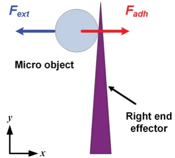
object and the end-effector. The schematic explanation is shown in Figure 1. The computation of the external force (Fext) is dependent on the movement
[image:4.595.282.461.542.703.2]of the end-effector. When the acceleration of the end-effector (a) is high enough, the object can be separated from the end-effector. However, to release the object at a suitable position with small landing area, the control of the release motion is necessary because a large amount of external force cannot guarantee position accuracy after separation [14]. To estimate the pull-off force, we assume several parameters based on the experimental conditions and [22]. In our system, a glass needle and polystyrene spheres with a diameter of 55 μm are utilized for an
DOI: 10.4236/wjet.2018.61005 85 World Journal of Engineering and Technology
end-effector and a target object, respectively. Based on the assumed parameters, the pull-off forces are calculated to be 2.03 × 10⁻⁵ N in air and 5.37 × 10⁻⁶ N in
water.
2.2. High-Speed Motions for Release
To verify the successful release and precise positioning of an object when using the proposed motions, five motions, including circular motions (clockwise and counterclockwise) and 1D motions (X, Y, and Z) were compared. Figure 2
shows five high-speed motions of the right end-effector. The red arrows in the figure represent the direction of each motion. To illustrate the shape of motions clearly, we draw each motion in different views, for example, Figure 2(a) and
Figure 2(b) in XY plane, Figure 2(c) in YZ plane, and Figure 2(d) and Figure
2(e) in 3D space. Figures 2(a)-(c) describe three 1D motions in the X-, Y-, and Z-directions. On the other hand, Figure 2(d) & Figure 2(e) displays circular motions in the clockwise and the counterclockwise directions.
3. Circular Motion for Precise Release
One of the important considerations in releasing an adhered object on the planned position is to reduce the velocity of the object before it reaches the sub-strate. In a micro-scale environment, although the inertial forces from the end- effector’s motion are very small, the accelerations of micro-objects are usually very high. Subsequently, the velocity of the object is able to increase in a very short time and the trajectory of the object could be difficult to control. Finally, the object can jump rapidly out of the visible area. The attachment position be-tween the end-effector and the micro-object are also vital factors for the trajec-tory of the object after separation. The high-speed camera provides the position of the target object and end-effectors; however, 3D position information, in-cluding Z-position, is generally difficult to acquire in a micro-environment. For
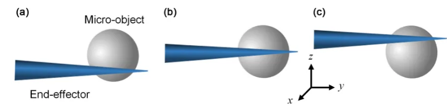
DOI: 10.4236/wjet.2018.61005 86 World Journal of Engineering and Technology Figure 3. Adhered position of an object before separation (a) adhered to the lower part (b) adhered to the center part (c) adhered to the upper part.
this reason, objects can be adhered to an end-effector in several patterns as shown in Figure 3. Owing to these difficulties, the prediction of an object’s landing trajectory is excessively complex. Therefore, a special motion that can release objects into a small landing area regardless of the contact position is needed. In this paper, circular motion is proposed for precise release.
To compare the velocity of the released object, we calculate the acceleration of the end-effector according to the motions. 1D motions that can be composed of the sinusoidal curve generate an acceleration which is directly proportional to the displacement in opposing direction. On the other hand, circular motions create a constant speed by changing the direction, which means that the object is accelerating (centripetal acceleration). However, since the initial speed of the motion is zero, we should consider the tangential acceleration and centripetal acceleration together until the desired speed is reached. In this section, the main assumption in order to compare two motions is that the maximum velocity and increased time to maximum velocity of two motions are same. In addition, the amplitude (A) and the angular velocity (ωn) of two motions are equal.
Accelera-tions of the 1D motion and the circular motion can be calculated by EquaAccelera-tions ((2) and (3)), respectively. A indicates the amplitude and ωn is the angular
ve-locity of the end-effector’s motion. According to Equation (2), when the dis-placement is maximum, the acceleration is maximum. Moreover, the maximum acceleration of the 1D motion is same as the centripetal acceleration of the cir-cular motion calculated by Equation (3) if t t> 1. The acceleration of circular
motions can be divided by the time (t1) when the end-effector reaches the
maximum velocity. The angular velocity is varied from 0 to ωn until t1, so it
relies on the time (t). After t1, the angular velocity is fixed as ω2 because the
end-effector makes a uniform circular motion. To estimate the acceleration of two different motions, we assume several parameters. For example, fn is
as-sumed to be 100 Hz and A is assumed to be 3 μm. Thus, the maximum velocity and the time to reach the maximum velocity of the 1D motion are calculated to be 1.9 × 10⁻³ m/s and 5 ms, respectively. Applying these values, we can compute
the acceleration of the circular motion until the time t1. At that time, the end-
effector accelerates to the desired speed (1.9 × 10⁻³ m/s) and θ is changed from
0˚ to 180˚ in the time interval of 5 ms (t1). Thus, the tangential acceleration and
DOI: 10.4236/wjet.2018.61005 87 World Journal of Engineering and Technology
m/s2 and 1.18 m/s2, respectively. After 1
t , the uniform circular motion can be formed, as a result, the centrifugal acceleration of the circular motion and the maximum acceleration of the 1D motion are calculated to be 1.18 m/s2. The
ex-ternal forces (Fext) also can be computed by using Equation (1). mp is assumed
to be 2.4 × 10⁻⁵ kg. Therefore, the external force of the circular motion is 2.98 ×
10−5 N when t1 and 2.84 × 10⁻⁵ N after 1
t , whereas, the force of the 1D motion is constantly changed from 0N to 2.84 × 10⁻⁵ N. As a result, the maximum force of
the 1D motion is identical with the force of the uniform circular motion.
2
1 1
a =ω x (2) where, x A= sin
( )
ω1t ,ω1=2πf1( )
2( )
2 21 2 1 2 2 , ,
A A t t
a
A t t
θ θ ω + ≤ = > (3)
where, ω =2 2πf2
From estimated values, we can assume trajectories of the released object by two types of motions. Not only to detach the object from the end-effector, but also to reduce the velocity of the object after release, the minimum amount of forces should be applied. In case of the 1D motion, when the end-effector reach-es the maximum displacement, the maximum force is applied and then the ob-ject will be released. On the other hand, the circular motion produces the same amount of forces before t1, thus the object will be released at that time.
Ob-viously, the magnitude of the exerted force of the two motions when the object is released is same as mentioned above. However, the velocity of the object after release can be guessed by considering the direction of applied forces. The force of the 1D motion is exerted on the adhered object in the same direction as the end-effector’s motion, so the object will be released in the same direction of the motion. In contrast, an object adhered to the end-effector that moves in a circu-lar path experiences the centrifugal force directed toward the center of the cir-cular motion and the tangential force. If the object is released, the centrifugal force will be vanished. Subsequently, the object will travel in the tangential di-rection with a constant speed. Thus, the force for release of the object is slightly reduced, which makes the objects travel shorter distance than the 1D motion.
DOI: 10.4236/wjet.2018.61005 88 World Journal of Engineering and Technology
both types of motions can be dependent on the frequency and the amplitude of the end-effector. As the frequency and the amplitude increase, the external forces will be increased, and subsequently, the object released from the strong external force will travel longer distance.
Based on the applied force and the direction of the motion, we can estimate the movement of the object after release. 1D motion in the X-direction makes an object move in a straight line in the X-direction, therefore, the object travels with further displacement than the proposed motions and may even be located out-side of the workspace. The object released by the 1D motion in Y-direction could be not only dropped into the substrate but also moved in the Y-direction with high velocity. Finally, the object also travels a long distance. The object ma-nipulated by 1D motion in Z-direction could be released in a straight line in the Z-direction and be finally located at the nearest position. However, the object can reach the substrate having high velocity due to the high acceleration and then the object can sometime bump into the substrate rapidly. In contrast, cir-cular motion creates an arc trajectory for an object. As an object moves in circu-lar motion, it constantly changes its direction. After the object is released, it moves in a straight line at constant speed, tangent to the circle at the point where the object is located. Subsequently, the object moves in a parabolic path after re-lease, causing the object to reach the substrate at a lower velocity than the former motions.
In this paper, we conduct the release task in air and liquid media together. Fd
in Equation (4) indicates the drag force of the fluid on a sphere. μ represents the dynamic viscosity of the medium (air: 1.85 × 10⁻⁵, water: 1 × 10⁻³ Pa⋅s) and V is
the relative velocity of the fluid with respect to the object.
6π
d b
F = − µR V
(4)
The drag force is able to reduce the velocity of the object to be applied in the opposite direction. In water, the dynamic viscosity has a stronger influence on the drag force of the fluid than in air. As the result, an object in water will be lo-cated at a closer position than in air in spite of the same external forces thanks to the high drag forces [22]. Nevertheless, motion in only one direction cannot en-sure precise positioning after release in an air environment for the reasons men-tioned. By analyzing the movement of objects after release, we conclude that the circular motion is better solution for precise releasing of micro-object than the 1D motion. This motion can release objects into the small landing areas in both media by using the centrifugal force, in addition, the motion can release object precisely regardless of the contact position thanks to the direction of the force.
4. Experimental Setup
4.1. Overall System for Micro-Manipulation
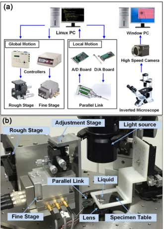
DOI: 10.4236/wjet.2018.61005 89 World Journal of Engineering and Technology Figure 4. Two-fingered micro-hand (a) configuration of the micro-manipulation system (b) overall micro-hand system.
DOI: 10.4236/wjet.2018.61005 90 World Journal of Engineering and Technology
Koki, Fine-503).
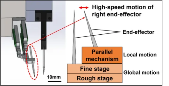
Local motion manipulated the right end-effector controlled by a compact pa-rallel link for grasping and releasing variously sized objects. The displacements of three PZT actuators (NEC TOKIN, AE0203D16) determined the 3D position of the right end-effector through a D/A board (Contec DA16-16(LPCI)L) and an amplifier (MATSUSADA, HJPZ-0.15Px3). For measuring the displacement of the PZT actuators, strain gages were implemented. In addition, the measured outcomes were transferred to the Linux PC through an amplifier (Kyowa MCD- 16A) and A/D converter (Contec AD16-16(PCI)EV). One adjustment stage, op-erated manually for adjusting the right end-effector with respect to the local mo-tion, moved 6 mm in a 3D direction with a resolution of 3 μm. To realize a large distance between the two end-effectors for grasping tasks, the manual stage was necessary. The two end-effectors of the micro-hand and the target objects were observed under an IX81 motorized inverted optical microscope using an objec-tive lens. The Windows PC displayed the images of the two end-effectors and objects captured by the high-speed camera (Photron FASTCAM MC2). Two fine-tipped glass needles, having a 23-mm length, 1-mm diameter, and tips with less than 1-μm curvature, were mounted in the micro-hand at the end of the pa-rallel link. The structure of two-fingered micro-hand is shown in Figure 5.
4.2. Structure of a Parallel Mechanism
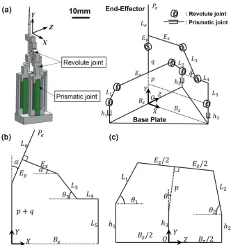
[image:10.595.237.520.564.708.2]In order to detach diverse sizes of objects from the end-effector at the desired locations, the 3D high-speed motions without uncontrollable vibration were ap-plied by using a parallel mechanism. The parallel manipulator was stiffer, faster, and more accurate than the serial mechanism. Therefore, we utilized the parallel mechanism to achieve 3D high-speed motions with precise positioning. The concise parallel link was a modified version of a previous structure [23], which used 3 PRR (prismatic-revolute-revolute) parallel mechanisms. Three PZT actua-tors were employed as prismatic joints that could be extended up to 10.7 μm, which yielded three degrees of freedom: two rotational in the X- and Z-directions and one translational in the Y-direction. A CAD image and the structure of the proposed model are described in Figure 6(a).
DOI: 10.4236/wjet.2018.61005 91 World Journal of Engineering and Technology Figure 6. Compact parallel link (a) structure of the parallel mechanism (b) the mechan-ism in the plane defined by p and the axis of the revolute joint at h3 (c) alignment of the linakge in the YZ plane.
To analyze the workspace of the parallel mechanism, inverse kinematics and structural analysis are utilized. In inverse kinematics of the mechanism, the length of piezo actuators (h1, h2, and h3) can be solved from a position of the
end-effector Pe (Pex, Pey, and Pez). The proposed mechanism in the plane
defined by p and the axis of the revolute joint located a distance h3 is displayed
in Figure 6(b). The linkage alignment of the model on the YZ plane is shown in
Figure 6(c). Applying the given values in Figure 6, the position of the end-effector can be computed.
(
)
sinex y e
P = E +L α
(5)
(
)
{
}
3 cos cos
ey y e
P =h + p q+ + E +L α θ (6)
(
)
{
cos sin}
ez y e
P = p q+ + E +L α θ
(7)
In this equation, we set Le to an extension of Ez. Based on Figure 6(b),
Equation (8) and Equation (9) are expressed as follows:
3 3 4
sin cos cos
y x x
DOI: 10.4236/wjet.2018.61005 92 World Journal of Engineering and Technology
3 3 5
cos sin sin
y x
p q E+ + α =E α+L θ +L (9)
With all of the above results, Equations ((5) and (6)), it is possible to find the length of the piezo actuator (h3). The angle α is calculated by Equation (5), and
the angle θ3 is obtained by substituting α into Equation (8). p and θ are
cal-culated by Equations ((9) and (7)), respectively. Finally, the value of h3 can be
solved by substituting the above parameters into Equation (6).
To solve h1 and h2, we concentrate on two polygons, divided by the p in
Figure 6(c). Equations ((10) and (11)) indicate the equation of each axial
direc-tion in the left polygon. On the other hand, Equadirec-tions ((12) and (13)) are calcu-lated by the right polygon.
1cos 1 zcos 2 z 2 sin
L θ +E θ =B +p θ (10) 1 1sin 1 3 cos zsin 2
h L+ θ =h +p θ+E θ
(11)
2cos 2 zcos z 2
L θ +E θ+pcosθ =B
(12)
2 2sin 2 zsin 3 cos
h L+ θ +E θ=h +p θ (13)
To find h1, h2 and h3, the angles θ1, θ2, and θ3 are computed by using
Equations ((10), (12), and (8)), respectively.
(
)
(
)
1
1 cos Bz 2 psin Ezcos 2 L1
θ = − + θ− θ (14)
(
)
(
)
1
2 cos Bz 2 psin Ezcos 2 L2
θ = − − θ− θ (15)
(
)
(
)
1
3 cos B L Ex 4 ysin Excos L3
θ = − − − α− α (16)
Finally, the value of h1, h2 and h3 can be found in terms of Pe. With all of
the calculated results, we find the piezo actuators values in the parallel link. Based on the above calculations, we get the axial displacement of the work-space. To be specific, the displacement in X-direction is 128 μm (−64~ 64 μm) and in Y-direction is 17 μm (0~ 17 μm). In the Z-direction, the end-effector can move 110 μm (−55~55 μm).
4.3. Controllable Motion Using a Parallel Link
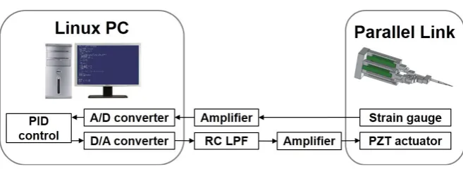
DOI: 10.4236/wjet.2018.61005 93 World Journal of Engineering and Technology Figure 7. Control scheme for the parallel link.
which could stretch to 10.7 μm simultaneously.
To generate enough force to separate the micro-objects, high-speed motions of the end-effector at high frequency (about 1 kHz) and amplitude were re-quired. The control scheme for the parallel link is shown in Figure 7. The values of strain gages measuring the extension of the PZT actuators were transmitted to the Linux PC trough an amplifier and an A/D converter. Applying the received sensor values, the orientation and position of the end-effector were computed. To move the end-effector to the desired position, the proper voltage determined by the computed data was applied to each PZT actuator via a D/A converter and an amplifier. In addition, to reduce uncontrollable oscillations at high speeds, a PID controller for feedback control and an RC circuit as a Low-Pass Filter were added. As a result, we succeed in decreasing irregular movement at the highest frequency (1 kHz) from over 5 μm to less than 0.5 μm. In this system, the dis-placement of the end-effector was reduced during high-speed motion. At the maximum frequency (1 kHz), the amplitude was decreased by 30 percent from the calibrated values.
Using this parallel link, we generated five types of high-speed motions Figure 2. 1D motions in the X-, Y-, and Z-directions consisted of step-functions with two steps. On the other hand, circular motions in the clockwise and the counter-clockwise directions composed of the combination of a sine function in the X-direction and a cosine function in the Z-direction with ten steps. Owing to the number of steps and the highest frequency of the parallel link for a step (1 kHz), the maximum frequency for the five motions was 100 Hz.
4.4. Manipulation of Various Sizes of Objects
DOI: 10.4236/wjet.2018.61005 94 World Journal of Engineering and Technology
[image:14.595.140.538.442.709.2]A high-speed camera capable of capturing images at 2000 frames per second to visualize the high-speed motion was applied. Because the maximum frequen-cy of a step in the motions studied was 1 kHz, in order to capture images that identify the direction and the speed of the objects, a high-speed camera that could capture images at over 1000 frames per second was necessary. The release experiments were performed at 20 μm above the substrate to avoid being af-fected by the motions of the end-effector. Each motion was repeated 8 times, and the performance duration for each motion was 100 ms. Room temperature was set to 24 ˚C. The experiment was performed in different environments; for ex-ample, with 55-μm microbeads in air, 10-, 25-, 55-μm microbeads in water, and 16-μm NIH3T3 cells in phosphate-buffered saline (PBS).
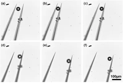
Figure 8 shows the manipulation process for a 55-μm microbead. Figure 8(a)
and Figure 8(b) show the grasping task, which included moving both end-effectors
close enough to the target object and moving the right end-effector to grasp the object. Figure 8(c) shows a release attempt without using any special method for moving the right end-effector. The object was then attached to the right end-effector. To release an object for precise positioning, the release height was a vital factor because it determined location accuracy after release [6] [9]. In this experiment, the release height was fixed to 20 μm by changing the Z-positions of both end-effectors (Figure 8(d)). The object sometimes bumped into the left end-effector after release. To prevent collisions between the object and the left end-effector during and after release, the right end-effector was moved manually by using the adjustment stage (Figure 8(e)). Finally, the release task using high- speed motions were performed (Figure 8(f)).
DOI: 10.4236/wjet.2018.61005 95 World Journal of Engineering and Technology
5. Experimental Results and Discussion
5.1. Release Conditions for Different Objects
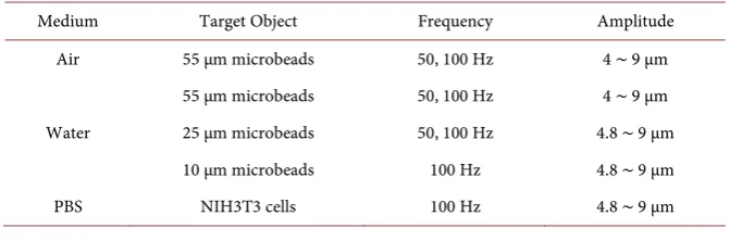
According to the sizes of objects and the environment, the range of frequency and amplitude of the end-effector that could release the adhered object was dif-ferent. To determine the possible frequency and amplitude of the end-effector for release in different environments and different object sizes, the maximum frequency was applied to adhered micro-objects by changing the amplitudes of the end-effector; then, lower frequencies were tested using the same values of amplitude. If the release of microbeads was not achieved or if the object moved outside of the visible area every time, these cases were excluded from the expe-riment. The ranges of amplitudes and frequencies for the end-effector using cir-cular motions according for different objects in different environments under the proposed conditions are shown in Table 1.
Specifically, at first, experiments using 55-μm microbeads in air were per-formed at the maximum frequency (100 Hz). As a result, when the amplitude of the end-effector was smaller than 4 μm, objects did not detach from the end-effector. On the other hand, when the amplitude was larger than 9 μm, objects flew out-side of the visible space. Thus, we decided that the useful range of the amplitude of the end-effector was from 4 μm to 9 μm except for 1D motion in the Y-direction. Thereafter, we applied this range of amplitudes at different fre-quencies (50, 25, 20, and 10 Hz). If the objects were released successfully at the same conditions, the frequency was selected. Finally, we determined that the frequencies of the motions were 50 Hz and 100 Hz. However, in the case of 1D motion in the Y-direction, only two amplitudes (1.2 μm and 2.4 μm) were ap-plied because the maximum movement of the end-effector in the Y direction was 2.4 μm at 100 Hz.
[image:15.595.205.541.619.730.2]In order to compare the release conditions between air and liquid environ-ments, the same range of amplitudes (4 ~ 9 μm) and frequencies (50 Hz and 100 Hz) in air were applied in the liquid environment. In the liquid environment, the objects were always located in the visible area (in contrast with the case in air); on the other hand, the adhered objects could detach from the end-effector when the amplitude or frequency were too low. For instance, 55-μm microbeads in water detached from the end-effector under the same conditions (amplitudes and frequencies) as in the air environment. However, 10- and 25-μm microbeads
Table 1. Release conditions according to objects.
Medium Target Object Frequency Amplitude Air 55 μm microbeads 50, 100 Hz 4 ∼ 9 μm
Water
DOI: 10.4236/wjet.2018.61005 96 World Journal of Engineering and Technology
and 16-μm NIH3T3 cells were not released from the end-effector when the am-plitude was lower than 4.8 μm at 100 Hz, and even 10-μm microbeads and 16-μm cells could not be detached when the frequency was 50 Hz and the am-plitudes were from 4.8 μm to 9 μm. From the results in water, it can be seen that, when the size of the microbeads is smaller, the required external forces calcu-lated by the frequency and the amplitude of the end-effector in Equations ((2) and (3)) for release are larger.
5.2. Release of Microbeads in Air
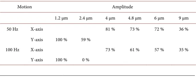
Experiments were conducted in different environments such as air, water, and PBS. First of all, the results of release in air are analyzed. In the environment of air, objects can sometimes move rapidly; as a result, objects can become located outside of the visible area. If microbeads (55-μm) after release moved inside of the visible area (512 μm × 512 μm), the release task was judged as a success; in the opposite case, the task was considered as a failure. Table 2 shows the success rate of release tasks in air according to the motions and the amplitudes of the end-effector. From these results, 1D motion in the X- and Y-directions can be seen to fail as the amplitude of the end-effector is increased. Moreover, the rela-tionship between the success rate and the frequency can also be established. Lower frequencies of the end-effector show higher success rates for release. On the other hand, 1D motion in the Z-direction and circular motion always suc-ceed in placing microbeads inside the visible area. If the displacement of the end-effector was over 9 μm, the object was located outside of the visible area at all times.
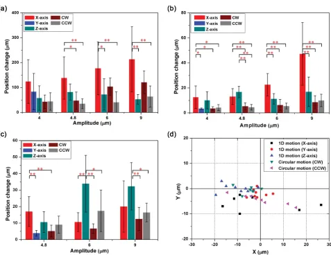
[image:16.595.207.539.610.742.2]To analyze the results of release tasks in terms of placement accuracy, the po-sition change after release was measured. Each motion was repeated eight times for statistical analysis. To compare every motion, the mean value and standard deviation of the displacement of the microbeads of the eight repeated motions were computed. Figures 9(a)-(c) show the results of the experiments. The bars indicate the mean value and the error bars express the standard deviation. 1D motion in the Y-direction was included in the smallest value of each motion be-cause the maximum values of the amplitude of the end-effector in the Y-axis (1.2 μm in air and 2.4 μm in liquid) were smaller than the smallest values for other motions.
Table 2. Success rate of release tasks in air.
Motion Amplitude
1.2 μm 2.4 μm 4 μm 4.8 μm 6 μm 9 μm
50 Hz X-axis 81 % 73 % 72 % 36 % Y-axis 100 % 59 %
DOI: 10.4236/wjet.2018.61005 97 World Journal of Engineering and Technology Figure 9. Experiment results (a) position change of 55-μm microbeads for motions in air (*p < 0.05, **p < 0.01) (b) position change of 55-μm microbeads for motions in water (*p < 0.05, **p < 0.01) (c) position change of NIH3T3 cells for motions in PBS (*p < 0.05, **p < 0.01) (d) placement position or the applied motions (NIH3T3 cells in PBS)
DOI: 10.4236/wjet.2018.61005 98 World Journal of Engineering and Technology
suitable for precise placement in air. The reason for more precise positioning with the counterclockwise (CCW) motion is that the direction of circular mo-tion has an effect on the posimo-tion of the object. The object moved in the clock-wise (CW) direction is pulled upwards and released from the end-effector whe-reas the counterclockwise circular motion pushes the object downwards. Finally, the object moved in the CCW direction will be located at a closer position to the end-effector than the CW direction in air.
5.3. Release of Microbeads in Water
The results of the release task in water are investigated. The same size of micro-beads (55-μm) was utilized for analyzing the relationship between the environ-ments of air and water. In this case, the microbeads after release were always placed in the visible area; consequently, the success rate was 100%. Figure 9(b)
displays the value of the position change of the microbeads according to the mo-tions at 100 Hz. 1D motion in 1the Y-direction and circular motion showed more precise placement than 1D motion in the X- and Z-directions at the same end-effector amplitude. For example, 1D motion in the X- and Z-directions were significantly different than other motions, whereas three motions (1D motion in the Y-direction and two circular motions) were not significantly different from each other. Although the amplitude of 1D motion in the Y-direction was too small to compare with other motions, this motion is suitable for successful re-lease. This is because 1D motion in the Y-direction was able to release the object in spite of the small amplitude while the other motions could not detach the same size of object using the same amplitude (2.4 μm). Thus, we conclude that the two types of circular motions and the Y-motion are proper motions for precise place-ment. In addition, from this figure, the relationship between end-effector ampli-tude and position change can be analyzed. As the ampliampli-tude of the end-effector is decreased, microbeads can be located at closer positions to the initial position.
5.4. Release of NIH3T3 Cells in PBS
DOI: 10.4236/wjet.2018.61005 99 World Journal of Engineering and Technology
[image:19.595.209.540.353.524.2]range of placement positions. In contrast, 1D motion in the Y-direction and clockwise circular motion had a small range of placement positions. From the experimental data, we could assume that clockwise circular motion and 1D mo-tion in the Y-direcmo-tion were better than other momo-tions in terms of object posi-tioning. The reason that the CW direction would place the objects on the smaller region than the CCW direction is that small object size could have an effect on the local fluid stream generated by the end-effector’s motion. The circular mo-tion creates a rotamo-tional flow around the end-effector whose direcmo-tion is the same as the direction of the motion of the end-effector [24] [25]. They observed a relationship between the distance from the center of the rotation and the an-gular velocity of the microbeads around the end-effector. For example, CW mo-tion of the end-effector creates a clockwise rotamo-tional flow, and the flow could push the object to the left side of the end-effector Figure 11(a). On the other hand, CCW circular motion produces a counterclockwise rotational flow, and the stream could pull the object towards the end-effector Figure 11(c). Howev-er, the final position of the object depends on the time when the object is re-leased from the end-effector since the performance time of high-speed motion is 100 ms. We could verify the phenomenon through Figure 9(d). In the graph,
Figure 10. Release of an NIH3T3 cell (a) before release (b) after release.
[image:19.595.211.539.556.694.2]DOI: 10.4236/wjet.2018.61005 100 World Journal of Engineering and Technology
the objects released by the CW motion were placed on the left side of the desired position, while it the objects detached by the CCW motion were not located on the fixed position. In addition, in the case of clockwise circular motion, small amplitude of the end-effector can guarantee more precise positioning, which is different from the case for other motions.
5.5. Comparison of Experimental Results in Air
and Liquid Environments
Based on the previous experimental data in different environments (air, water, and PBS), the proposed motions that can improve placement precision after re-lease are verified. To analyze the results of the experiments, at first, different frequencies and amplitudes of the end-effector were examined to ascertain whether release was achieved or not. Then, five motions were applied in order to compare the position accuracy after release. As a result, several outcomes can be obtained.
First, micro-objects in air are located within a larger space than in liquid. To be specific, the objects in air are positioned over 50 μm from the initial position and are not even located in visible areas, whereas the values of the position change of objects in liquid are less than 50 μm. This outcome agrees with the former assumption that the hydrodynamic force in water is stronger than in air owing to the higher dynamic viscosity in the former medium, which hinders the object from moving quickly a short time after separation; finally, the object in water will be located at a closer position than in air.
Second, in every environment, we can find the relationship between the am-plitude and the position accuracy: the smaller the amam-plitude, the better the placement accuracy achieved. This result verified that the external force decided by the amplitude and frequency of the end-effector in Equations (1)-(3) increas-es with the increase of amplitude. Consequently, the minimum amplitude that is able to detach objects from the end-effector can release micro-objects with high position accuracy.
Finally, for different environments, active release motions with high position accuracy are different. In the case of air, counterclockwise circular motions can release microbeads at the nearest position from the initial position. In the case of water, 1D motion in the Y-direction and circular motions can detach micro-beads with small position changes. Lastly, 1D motion in the Y-direction and clockwise circular motions can separate NIH3T3 cells precisely. In the second section, we proposed these motions by analyzing the movement of objects after release. From these experimental results, we verified the assumption that the proposed motions can release and place objects precisely.
6. Conclusion
DOI: 10.4236/wjet.2018.61005 101 World Journal of Engineering and Technology
sizes of objects and different environments (air, water, and PBS). To release micro-objects, the status of a micro-object after release was analyzed in two dif-ferent environments (air and liquid media). From the analyses, circular motion for the air environment, and circular motion and 1D motion in the Y-direction for the liquid environment are proposed for improving placement accuracy. To verify the efficiency of the proposed motions, five motions, including 1D motion in the X-, Y-, and Z-directions and circular motion (CW, CCW) were applied by comparing the position change after the release of 10-, 25-, and 55-μm micro-beads and NIH3T3 cells; we then applied statistical methods. As the result, we verified the fact that the proposed motions can release objects at suitable posi-tions with high position accuracy. In the future, we will extend this approach to the automatic system that can release objects on the precise position.
Acknowledgements
This work was partially supported by the Grant-in-Aid for Scientific Research (A) (JP16H02321), Grant-in-Aid for Young Scientists (A) (JP16H06076) from the Ministry of Education, Culture, Sports, Science and Technology of Japan.
References
[1] Fantoni, G. and Porta, M. (2008) A Critical Review of Releasing Strategies in Mi-croparts Handling. International Precision Assembly Seminar, Chamonix, 10-13 February 2008, 223-234.
[2] Saito, S., Miyazaki, H.T., Sato, T. and Takahashi, K. (2002) Kinematics of Mechani-cal and Adhesional Micromanipulation under a Scanning Electron Microscope.
Journal of Applied Physics, 92, 5140-5149.
[3] Fuchiwaki, O., Ito, A., Misaki, D. and Aoyama, H. (2008) Multi-Axial Micromani-pulation Organized by Versatile Micro Robots and Micro Tweezers. IEEE Interna-tional Conference on Robotics and Automation, Pasadena, 19-23 May 2008, 893-898. https://doi.org/10.1109/ROBOT.2008.4543318
[4] Hériban, D. and Gauthier, M. (2008) Robotic Micro-Assembly of Microparts using a Piezogripper. IEEE/RSJ International Conference on Intelligent Robots and Sys-tems, Nice, 22-26 September 2008, 4042-4047.
https://doi.org/10.1109/IROS.2008.4650932
[5] Horade, M., Kojima, M., Kamiyama, K., Kurata, T., Mae, Y. and Arai, T. (2015) Development of an Optimum End-Effector with a Nano-Scale Uneven Surface for Non-Adhesion Cell Manipulation using a Micro-Manipulator. Journal of Micro-mechanics and Microengineering, 25, Article ID: 115002.
https://doi.org/10.1088/0960-1317/25/11/115002
[6] Rong, W., Fan, Z., Wang, L., Xie, H. and Sun, L. (2014) A Vacuum Microgripping Tool with Integrated Vibration Releasing Capability. Review of Scientific Instru-ments, 85, Article ID: 085002. https://doi.org/10.1063/1.4891695
[7] Takahashi, K., Kajihara, H., Urago, M., Saito, S., Mochimaru, Y. and Onzawa, T. (2001) Voltage Required to Detach an Adhered Particle by Coulomb Interaction for Micromanipulation. Journal of Applied Physics, 90, 432-437.
https://doi.org/10.1063/1.1379353
DOI: 10.4236/wjet.2018.61005 102 World Journal of Engineering and Technology (2015) Piezo-Actuated Parallel Mechanism for Biological Cell Release at High Speed. Biomedical Microdevices, 17, 98. https://doi.org/10.1007/s10544-015-0001-7 [9] Chen, T., Pan, M., Wang, Y., Liu, J., Chen, L. and Sun, L. (2012) Manipulation of
Microobjects Based on Dynamic Adhesion Control. International Journal of Ad-vanced Robotic Systems, 3. https://doi.org/10.5772/51507
[10] Demaghsi, H., Mirzajani, H. and Ghavifekr, H.B. (2013) Design and Simulation of a Novel Metallic Microgripper using Vibration to Release Nano Objects Actively. Mi-crosystem Technologies, 20, 65-72. https://doi.org/10.1007/s00542-013-1888-7 [11] Haliyo, D.S., Régnier, S. and Bidaud, P. (2003) Manipulation of Micro-Objects
us-ing Adhesion Forces and Dynamical Effects. Experimental Robotics VIII. Sprus-inger, Berlin, 382-391.
[12] Landolsi, F. and Ghorbel, F.H. (2015) Modeling of Multisample Nanoplacing. Jour-nal of Dynamic Systems Measurement and Control, 137, Article ID: 024502. [13] Osawa, S. and Ozaki, K. (2011) Automatic Pickup and Release of Particle by Depth
Estimation Method with Micromanipulators for Particle Sorting System. IEEE/SICE International Symposium on System Integration, Kyoto, 20-22 December 2011, 857-862. https://doi.org/10.1109/SII.2011.6147561
[14] Fang, Y. and Tan, X. (2006) A Dynamic JKR Model with Application to Vibrational Release in Micromanipulation. IEEE/RSJ International Conference on Intelligent Robots and Systems, Beijing, 9-15 October 2006, 1341-1346.
https://doi.org/10.1109/IROS.2006.281920
[15] Chen, B.K., Zhang, Y. and Sun, Y. (2009) Active Release of Microobjects using a MEMS Microgripper to Overcome Adhesion Forces. Journal of Microelectrome-chanical Systems, 18, 652-659. https://doi.org/10.1109/JMEMS.2009.2020393 [16] Watanabe, T., Iwasaki, M., Matsumura, H. and Jiang, Z. (2009) Study on Adhesion
Force Reduction and State Estimation by Piezo-Transducer. IEEE International Conference on Robotics and Automation, Kobe, 12-17 May 2009, 2211-2216. https://doi.org/10.1109/ROBOT.2009.5152254
[17] Kim, E., Kojima, M., Kamiyama, K., Horade, M., Mae, Y. and Arai, T. (2015) Re-leasing and Accurate Placing of Adhered Micro-Objects using High Speed Motion of End Effector. IEEE/RSJ International Conference on Intelligent Robots and Sys-tems, Hamburg, 28 September-3 October 2015, 2006-2011.
https://doi.org/10.1109/IROS.2015.7353642
[18] Arai, F., Andou, D. and Fukuda, T. (1996) Adhesion Forces Reduction for Micro Manipulation Based on Micro Physics. The 9th Annual International Workshop on Micro Electro Mechanical Systems, San Diego, 11-15 February 1996, 354-359. https://doi.org/10.1109/MEMSYS.1996.494007
[19] Israelachvili, J.N. (2011) Intermolecular and Surface Forces. Academic Press, Cam-bridge.
[20] Tomas, J. (2006) Mechanics of Particle Adhesion. Particles on Surfaces, 8, 183-229. [21] Rollot, Y., Régnier, S. and Guinot, J.-C. (1999) Simulation of Micro-Manipulations:
Adhesion Forces and Specific Dynamic Models. International Journal of Adhesion and Adhesives, 19, 35-48. https://doi.org/10.1016/S0143-7496(98)90055-0
[22] Gauthier, M., Régnier, S., Rougeot, P. and Chaillet, N. (2006) Analysis of Forces for Micromanipulations in Dry and Liquid Media. Journal of Micromechatronics, 3, 389-413. https://doi.org/10.1163/156856306777924699
DOI: 10.4236/wjet.2018.61005 103 World Journal of Engineering and Technology
IEEE/RSJ International Conference on Intelligent Robots and Systems, Tokyo, 3-7 November 2013, 1525-1530. https://doi.org/10.1109/IROS.2013.6696551
[24] Hayakawa, T., Sakuma, S., Fukuhara, T., Yokoyama, Y. and Arai, F. (2014) A Single Cell Extraction Chip using Vibration-Induced Whirling Flow and a Ther-mo-Responsive Gel Pattern. Micromachines, 5, 681-696.
https://doi.org/10.3390/mi5030681
[25] Kim, E., Kojima, M., Xiaoming, L., Hattori, T., Kamiyama, K., Mae, Y. and Arai, T. (2017) Analysis of Rotational Flow Generated by Circular Motion of an End Effec-tor for 3D Micromanipulation. ROBOMECH Journal, 4, 5.