Internship Huntsman
The design of falling film
evaporators
Karlo Kok (s0206172)
December 27, 2013
Internship Huntsman
The design of falling film
evaporators
Karlo Kok (s0206172)
December 27, 2013
Internship Huntsman Polyurethanes Rotterdam
September - December 2013
Rotterdam, The Netherlands
Supervisor Huntsman
ir. J.M. Rutten
Preface
From September till December 2013 I did an internship at a MDI Plant of Huntsman Polyurethanes in the Port of Rotterdam.The chemical industry has fascinated me since my youth and as a me-chanical engineer I got the opportunity to do an internship within this chemical company. The Huntsman site has several plants and I got the opportunity to work at the large MDI plant at site. This plant is quite impressive as well by size as by complexity as by types of equipment. The Rotterdam site comprises several departments, so it was possible to get familiar with other disciplines. This report will summarize my time within the Huntsman company and explain the assignment I did for this company.
Summary
Huntsman Polyurethanes Rotterdam uses tube falling film evaporators in their processes. This type of evaporators is a proven concept and has been used in various chemical plants in the past 50 years. Huntsman wanted to know if there is a alternative for these evaporators available. They received the message that their evaporators might be outdated and they would like to improve their production sites with better equipment.
The report will start with an introduction of the MDI plant in the Port of Rotterdam. An brief overview of the different plants and processes at the production site will be given. The subject of the internship is mainly focused on the Keystone part of the MDI2 plant. This part is analyzed to get the operation conditions for the falling film evaporators. The Keystone part of the plant is operating for half a year and it operates very well. Some adjustments has been done on the initial design to improve the system. The falling film evaporators operate very stable and according to their design.
The flow inside the falling film evaporators is analyzed to get more understanding in the working principles. The two phase inside the evaporators is quite complex and requires a numer-ical solution which is checked with a physnumer-ical model. This was not possible during the internship, but the analysis with simple empirical equations gave good results. The empirical relations ap-proximate the operating conditions with an accuracy of 5%. The report will discuss some of the working principles of the current tube evaporators. The evaporator is designed with some special features such a specific pipe diameter and inserts.
In the last part of the report the alternatives for the current evaporator will be discussed. The chosen concept is a vertical plate falling film evaporator. This evaporator has some advantages over the current evaporator. The weight of the evaporator can be reduced with 30% and pressure drop in the MDI flow will be lower. The working principles of the new evaporator will also be explained in this section.
The report concludes with the conclusions that the current evaporators operate good, the given equations approximate the operation conditions well and the plate evaporator could be an interesting option for the replacement of current evaporators. It is recommended to look at the option for plate evaporators for a replacement or a new plant. If desired a numerical model could be made for better understanding of the flow inside the evaporators.
The process data, such as throughputs, split ratios, chemical properties and detailed equip-ment descriptions, of the plant is confidential information. All the confidential data is removed from the report. The confidential report is only available for employees of Huntsman.
Contents
Preface 3
[image:5.595.88.507.110.707.2]Summary 4
Table of symbols and definitions 7
1 Introduction 8
1.1 Company profile . . . 8
1.2 Rozenburg site . . . 8
1.3 The chemical process . . . 8
1.4 Keystone . . . 9
1.5 MDI Properties . . . 11
2 Problem definition 12 2.1 Overall performance . . . 12
2.2 The fluid dynamics problem . . . 12
2.3 Idea generation . . . 12
2.4 Design . . . 12
3 Work plan 13 3.1 Initial scheme . . . 13
3.2 Visited departments . . . 13
4 Keystone Analysis 14 4.1 Introduction . . . 14
4.2 Flow calculations . . . 14
4.3 Overall statements . . . 15
4.4 C3901 . . . 15
4.5 E3901 . . . 16
4.6 E3902 . . . 17
4.7 C3902 . . . 18
5 Analysis 20 5.1 Falling Film Fluid Dynamics . . . 20
5.2 Literature . . . 20
5.3 Flow profiles . . . 22
5.4 Heat transport . . . 24
5.5 Mass flux . . . 25
5.6 Design considerations . . . 27
6 Design 29 6.1 Design specifications . . . 29
6.2 Working principles . . . 29
6.3 Alternatives . . . 31
6.4 Concept choice . . . 33
6.5 Design considerations . . . 34
6.6 Manufacturers . . . 37
8 Recommendations 39
9 Literature 40
Table of symbols and definitions
A= surface area[m2]
b= width between dimples[m]
δ= film thickness [m]
D= diameter[m]
dy= distance from neutral bending axis[m]
g= gravitational accelerationhm
s2
i
h= plate thickness[m]
I= Area moment of Inertia[m4]
k= thermal conductivity
W
m·K
ktpa= year production
106kg
year
Lc = characteristic length[m]
L= length between dimples[m]
µ= dynamic viscosity
kg m·s
ν = kinematic viscosityhm
s2
i
N u= Nusselt number[−]
P = pressure[P a]
±pc=−1 for counter current flow/+ 1 for co current flow P r= Prandtl number[−]
ρ= density liquid
kg
m3
Re= Reynolds number[−]
S= tensile strength[P a]
vz= average velocityhm
s
i
w= mass flow rate
kg s
1
Introduction
1.1
Company profile
The Huntsman company is a multinational chemical company founded in 1970 as a packaging producer. In four decades the company grew from a relatively small packaging producer to multi billion dollar company specialized in dye products, polyurethanes and all kind of other chemical materials. Huntsman has production plants all over the world. One of their plants is located near Rozenburg in the Port of Rotterdam.
1.2
Rozenburg site
The Rozenburg site in the Port of Rotterdam began as an ICI production plant for different types of polymers. These include the production of acrylics, polyurethanes and nylons. After a series of bad investments ICI had to shutdown its business and the plants on Rozenburg site were sold to various companies. Huntsman acquired the polyurethane business of ICI in 1997. The nylon production was sold to Invista, the acrylics plant to Lucite and Evides has now control over the water treatment on site. Also new plants were built on the Huntsman site, e.g. a hydrogen plant by Air Liquide and a stream/electricity plant by Eurogen.
The production of polyurethanes consists of two production locations, called upstream and downstream. The upstream produces the base component of polyurethanes i.e. Methylene Di phenyl di Isocyanate abbreviated as MDI. The MDI production on Rozenburg site started around 1961 with a production ofCdata kilotons a year and grew to Cdata kilotons of MDI a year in 2013. The production is divided over two plants called MDI1 and MDI2, where MDI2 produces the major part. The downstream part consists of three divisions, called polyols, formulates and variants. Polyols produces the reacting component for polyurethanes, formulations and variants produce intermediate products for customers.
The Rozenburg site is also home to various other departments. Some of them are directly supporting the production of plants on site and others also support other Huntsman facilities. Some of the supporting are the maintenance department, quality control department and the Environmental, Health and Safety department. The Rozenburg Technology Group is a depart-ment which supports the plants at site.. This group develops new sections and optimizations for existing plants as well as complete new facilities. The supply chain department for Europe, Asia and Africa is also located at Rozenburg site.
The subject is focused on the MDI plant and this process will be explained in this report.
1.3
The chemical process
The production of MDI at Rozenburg site in its simplest form consists of four steps. The first two steps are reactions to form the MDI and the last two steps separate the MDI into different compositions. The process is described in a simple form to give an idea of the production in this plant. Many separation steps are neglected.
H2
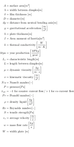
[image:9.595.178.421.94.281.2]N NH2
Figure 1: DADPM Molecule
O C
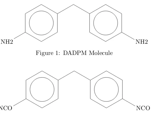
N NCO
Figure 2: 4,4-MDI Molecule
After the formation of DADPM the next step is an isomerisation reaction. This reaction converts the secondary amines in the DADPM molecules to primary amines. The primary amines will have a NH2 chain at either side of the molecule. These chains are important for the final MDI product as will be explained further on. The DADPM mixture will go through a series of separation steps to separate the DADPM from the other compounds.
The second step in the process is the formation of MDI. The first reaction in the second chain is the formation of phosgene. Chlorine and carbon monoxide react in the presence of an active carbon catalyst to phosgene. The DAPDM is mixed with a solvent called MCB (monochloroben-zene). The phosgene and the DADPM are fed to a reactor and MCB (monochlorobenzene) and the MDI forms through a series of five reactors. A workup section will separate the phosgene, MDI, HCl and MCB.
The third step in the process is the separation of MDI into the light compounds and heavy compounds. The MDI consists of polymeric chains with a length varying between 2 and 9 links. During this separation step the short chains of two links are separated from the polymeric mixture. This separation step is done by evaporating the short chains of the MDI in a vacuum column. The long chains will remain in the solution, because these cannot be evaporated due to their high boiling point. Also a part of the short chains will remain in the solution. This is necessary to give the polymeric mixture the right specifications to be sold as a product.
The distillate produced in step three still consists of three different types of molecules. These are 2,2-MDI, 2,4-MDI and 4,4-MDI, where the 2,2-MDI fraction is quite small. 4,4-MDI is the most profitable form of MDI, because it gives the best product. The products are separated by a crystallization process into pure MDI and mixtures of 2,4 and 4,4-MDI, called for example MI37. The crystallization process separates these component based on the difference in solidification temperature. On site there are three types of crystallizers with different processes, but it is not relevant to explain their working principles in this report.
1.4
Keystone
NCO NCO
Figure 3: 2,4-MDI Molecule
CH2
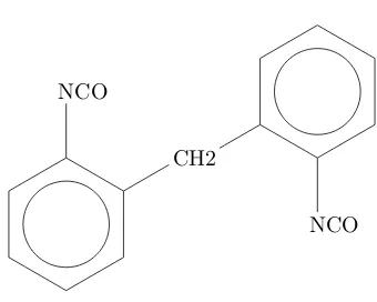
[image:10.595.211.381.197.333.2]NCO NCO
Figure 4: 2,2-MDI Molecule
income. This new part of the plant is subject of the internship and therefore it will be explained in more detail than other parts of the MDI plant.
The process in step three starts with the separation of the light components from MDI. The precursor MDI from step two is collected is a buffer vessel and stored at 180 C for a while. From the vessel the MDI is sprayed in the so called stripper column and falls on a structured packing. From the bottom of the column rises a stream of gaseous MDI and it interacts in the structured packing with the fluid. A stream of gaseous volatile components and di iso will flow to the top and into another column. The di isos are condensed and sent back to the stripper column and the volatiles are removed. The liquid MDI will fall to the bottom of column.
The bottom stream is separated in two streams. The first will feed the evaporator of the stripper column. This evaporator will produce the gaseous MDI needed to drive the stripper column. The MDI is evaporated by the latent heat of condensing steam. The second stream will feed the evaporator of the heavies column. This evaporator is bigger than the one of the stripper column, but the working principle is the same. The short chains of MDI will be partly evaporated and the rest will directly flow to the bottom of the heavies column. The gaseous MDI will rise within the column to a structured packing where it interacts with a liquid flow. The liquid flow is made by partly condensing the gaseous flow. This is done by a two layer condenser within the column. The non condensed MDI will flow to another column where it will be condensed. The distillate MDI will flow to the crystallizers at site.
1.5
MDI Properties
The MDI properties are from the specification sheets of the evaporators. The properties are given for a specific temperature and pressure. These values are corrected in the calculation for different temperatures and pressures.
MDI Properties Liquid Vapour
Temperature [C] 208.77 216.39 Pressure [mbar] 0.012 0.012
Densityhmkg3
i
1155 0.5
Viscosity [mP a·s] 2.1 0.077 Specific heathkgkJ·Ki 1.79 1.558
Latent heathkJkgi 342.7
Thermal conductivity W m·K
2
Problem definition
The assignment during the internship is focused on the evaporators at the MDI plants of Hunts-man. The question of Huntsman company is whether it is possible design an alternative evap-orator for the future. The current design of the tube falling film evapevap-orator might be outdated and the company wants to know whether there is a good alternative.
The second motive for an alternative is the costs of a tube evaporator. A falling film evapo-rator as build on site costs around a half to one million Euro which is major part of the project costs. When these costs could be cut, the overall project costs will be reduced. This could save money what can be invested in other parts of the plant and it will reduce the payback time of a project. The project will become more economically feasible and will be approved by the board earlier.
This assignment consists of a number four parts which will be described in the sections below.
2.1
Overall performance
Keystone is in operation for a half a year. The question is if it operates on design specifications or that it operates on other conditions. The system has to be analyzed as a complete system to give the essential information on the process conditions of the evaporators. The system is analyzed with use of the process data of various throughput rates.
2.2
The fluid dynamics problem
The exact operation of the evaporators is unknown. So are the layer thickness and vapor and layer velocity unknown. In this part of the assignment is tried to get a better overview of the working principle. This will give more insight in the challenges of this project.
2.3
Idea generation
For a new type of evaporator some existing solutions and new ideas are described and analyzed. This section will discuss several design problems and the solutions to these problems. At the end an feasible alternative for the current falling film evaporator is presented.
2.4
Design
3
Work plan
The initial work plan of the internship is described in section 3.1. During the internship became clear that the assignment was more complicated than at first thought. The analysis of the Keystone project took more time than expected and the overall problem with two phase flow was hard to describe. So it is decided to stop the assignment after the idea generation. The final presentation was given at 20th of December and the report is delivered before Christmas.
The office was located at the MDI2 plant on the Rozenburg site. The process engineers, support team and the process operators who are responsible for the plant are in this building. The location of the office gave the opportunities to explore the plant, getting explanation by several people and see the whole operating process including all the problems that could arise during operation.
The visited departments are listed in section 3.2.
3.1
Initial scheme
1 – 15 Sept. Getting familiar with the people and the factory
15 Sept. – 15 Oct. Analysis Keystone
15 – 31 Oct. Analysis Evaporators
1 Nov. Presentation
1 – 15 Nov. Idea generation
15 Nov. – 15 Dec. Detailed design
15 – 31 Dec. Report
31 Dec. Final presentation
3.2
Visited departments
Downstream production Rozenburg Technology Group
Maintenance Department
Projects Department
Process Chemistry
Supply Chain
Pilot Plant One
V3901 C/E3901
C/E3902
E
F
G D
B
C L
K J
[image:14.595.153.445.99.229.2]A
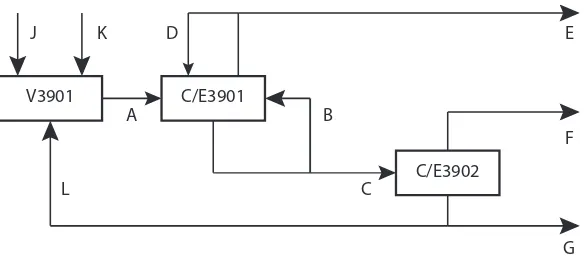
Figure 5: Overview of streams in Keystone plant
4
Keystone Analysis
4.1
Introduction
The Keystone part of the plant is analyzed during the internship. This analysis is necessary to collect the important data for the analysis of the falling film evaporators. This analysis makes use of real world data collected from the plant computers. This data is compared with design data which is available for three situations i.e. half rate, full rate and an other half rate throughput, called Nov, with a different distillate output. The precursor flow for half rate isCdata tonnes/h and for full rate is Cdata tonnes/h. The half rate case is compared with the data on 21st of September which has a throughput of Cdata tonnes/h, full rate case with the data of 26th of June which has a throughput of Cdata tonnes/h and the Nov. case with the data of 17th of November.
Keystone is designed to work with various throughputs. The input depends on the output of the MDI plants, the demanded products and the supply from MDI plants in Louisiana (USA) and China. The data on chosen dates can be easily compared with the conditions of the design data. The small variation in throughput is negligible for the analysis of Keystone.
4.2
Flow calculations
The calculations on the evaporators are based on the analysis of process data. This data shows some little deviations between the ingoing and outgoing streams of the evaporator. This is due to the residence time of the product in the system. All these deviations are within a margin of 5% and are not adjusted to get a completely matching mass balance. Correcting the mass balance for these deviations could bring more uncertainties, so the balance is not adjusted.
Some of the streams in Keystone are not measured. These flows are important for analyzing the complete system and these can be calculated by three equations. The Keystone equipment are considered as black boxes for now. A simple overview of Keystone can be found in figure 5. The unknown streams are streams C, F and L and these can be calculated by equations 1 to 3.
C=A−E (1)
L=A−J−K−∆storage (2)
C3901 Design Operating C3902 Design Operating half rate Cdata Cdata Cdata Cdata
[image:15.595.158.442.100.140.2]full rate Cdata Cdata Cdata Cdata
Table 1: Pressures E3901
The distillate rate F is also calculated by the work done by the condenser E3904. The calculation gives a value which is higher than the calculation above. This is due to the small temperature difference in the cooling liquid. The temperature sensor cannot detect very small temperature differences, but these temperature differences do have an enormous impact on the distillate calculation. Finally it is chosen to calculate the distillate rate by the internal streams in the stripper column.
For the analysis flow E is assumed the same as the flow in the design. This flow is not measured because it is not of importance for the system and it is very small compared to the other flows. This flow contains some invaluable volatiles and the flow is between the 30 and 60 kg/h. This assumption does also explain that flow C can be assumed equal to flow A.
4.3
Overall statements
4.3.1 Pressures
The operating pressures in Keystone are the same for column E3901 and lower for column C3902. The pressures are given in table 1. The lower pressure will have a positive effect on the vapor liquid equilibrium of MDI. Under these pressure conditions it will be easier to evaporate a part of MDI fluid.
4.3.2 Temperatures
The operating temperatures are lower than the design temperatures. The design has a heat exchanger to preheat the MDI before entering the stripper column. This heat exchanger is removed in the final design and the MDI is now heated inside the stripper column. The overall temperature difference with the design is about 10°C. The lower operating temperatures result in negative effects on the vapor production.
The combination of the lower pressure and temperature in the E3902 column will result in a equilibrium that will act relatively the same as the design conditions. The lower temperature in the E3901 column are not compensated by the pressure. This will have a negative influence on the vapor production as can be seen in the section 4.4
4.4
C3901
The analysis of the stripper column is more complicated than the analysis of the removal heavies column. The is mainly due to the flash that takes place at the top of the column. The top of the stripper column will act as a flash vessel. In a flash vessel a part of the liquid will evaporate due to a pressure drop. As described in sections 4.3.1 and 4.3.2 the pressures and temperatures are lower than in the original design. This variation in process conditions has influence on the amount of liquid that will evaporate.
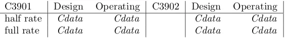
Figure 6: Flash top E3901
sent to a separate flash vessel. The results of this analysis can be found in figure 6. The actual flash is only 10% of the information generated with Aspen Plus.
The structured packing in the column is primarily used for heating the MDI flow. Most of the vapor entering the packing from the bottom condenses and the free latent heat heats up the MDI liquid which enters at the top of the packing by 20 to 30°C. The vapor flow that exits the top of the packing is only around 150 kg/h.
The vapor flow from the flash and the packing are combined and sent to a condenser. The total amount of condensed vapor is calculated real time by the temperature rise of the cooling fluid. By this calculation the output of the condenser was higher than vapor input. The first assumption was that the calculated vapor input was incorrect. The calculations were checked and seemed correct.
The second assumption was that the real time calculation was incorrect and for this assump-tion the control settings were analyzed. The calculaassump-tion for the energy absorbed by the cooling liquid is correct, but the calculation of the condensed mass is not correct. The mass flow is calculated by the latent heat of MDI at 180°C. But the condensate is also cooled down 110°C to 70°C. The calculation is not corrected for this temperature drop. The actual heat removed from a kilogram of MDI is 50% higher and this results in a 33% lower condensate flow.
The corrected mass flow calculation still gives some deviations in the overall balances. The calculation of the condensate flow depends on the temperature difference of the cooling liquid and this is less than 1°C. The temperature measurement is not designed to see deviations below a tenth of a degree and with a high mass flow this could lead to large deviations.
The flow to the condenser is only a small fraction of the flow specified in the design. This signifies that the column does not remove large amounts of volatiles. The fraction volatiles in the design charts was assumed relatively high. Currently the volatile fraction is much lower and the low column duty does not influence the final products.
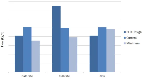
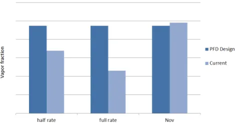
4.5
E3901
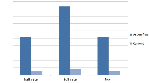
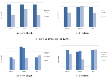
(a) Flow (kg/h) (b) Fraction
Figure 7: Evaporator E3901
(a) Flow (kg/h) (b) Fraction
Figure 8: Evaporator E3902
the steam flow in the full rate case. The information can be found in the figure 7.
The output of the evaporator is checked with the mechanical design data and the steam flow in the full rate is relatively high compared to the evaporation rate. The full rate vapor output is extrapolated to the maximum design vapor output and this results in a steam flow which is 11% higher than the maximum steam flow. The problem is that the steam flow is limited by the pressures in the very high pressure steam ducts and cannot become higher. So under current operations conditions the evaporator will not reach its maximum evaporation rate.
This problem could be solved by raising the inflow temperature by a few degrees. The evaporator is designed to work at an eight degree higher inflow temperature.
4.6
E3902
Figure 9: Condensate Flow E3903
4.7
C3902
The heavies column C3902 consists of three parts: the evaporator E3902, the structured packing and the condenser E3903. The evaporated vapor by the evaporator is calculated by the steam input. The heat transfer in this unit consists of the latent heat of evaporation and specific heat due to temperature drop.
The operation conditions of the E3903 are not adjusted for the reduced vapor flow. The condenser delivers a higher duty than specified in the process design. For the half rate case the condensate flow is inCdatacompared toCdatakg/h in design. The distillate flow in the current situation is lower than the distillate flow specified in the design. According to the design it is necessary to condensate only 23% of the vapor flow and this would result in a flow of onlyCdata
kg/h. This could also reduce the duty of the evaporator by 10% and deliver a small energy efficiency for the plant.
The relations between the design, the current and the minimal required condensate flows are given in figure 9. For the full rate case holds the same statement as for the half rate. The distillate flow is quite small compared to the original flow and the condensate flow could be reduced toCdatakg/h. The condensate flow for the Nov. case is equal to the minimum required flow.
The process description indicates that condenser E3903 should produce at leastCdata kg of condensate per hour. This is the minimal flow needed to completely wet the structured packing inside the column. The condensate washes the tri-isos molecules out of the vapor flow. If this process does not wash all of the tri-isos molecules, the produced distillate will be worthless.
The reduction of the condensate flow will affect the composition of the distillate flow. The 4.4MDI has a higher boiling point than the 2.4MDI and is likely to condense earlier. So the condensate has a relatively high fraction of 4.4MDI. When this condensate flow is reduced the distillate the 4.4MDI fraction will become higher which is favorable for the pure production in the last step. This could be tested by reducing the condensate flow in small steps.
4.7.1 Irregularities half rate case
Figure 10: Fraction distillate of total flow
5
Analysis
5.1
Falling Film Fluid Dynamics
The fluid dynamics of a falling evaporating film are quite complex. An evaporation fluid dynamics problem has to deal with two phases i.e. the liquid phase of the film and the vapor phase of the evaporated product. The same applies to the condensation problem of the steam. The film condensation and evaporation in a falling film evaporator is shown in figure 11. At the steam side the condensate film is slowly build by the condensed steam. At the same time the MDI starts evaporating into the vapor phase and the film thickness decreases.
The fluid problem of condensing steam is not as significant as the fluid problem of evaporating MDI. This will be explained by calculations in the coming chapter. The fluid problem of the evaporating MDI is complex and it consists of many variables.
Film velocity: The velocity of the film is influenced by many factors. The velocity at the beginning of the pipe is unknown, gravity will accelerate the flow while the wall will decelerate the flow. The vapor will influence the film velocity and could cause disruptions in it.
Vapor velocity: The acceleration of the vapor can be calculated, but it highly depends on the calculation method.
Film thickness: The film thickness will decrease when the fluid evaporates. This will influence the film velocity and the heat transfer to the film. The film thickness on a single point is hard to calculate.
Viscosity and Density: The viscosity and density will change during the evaporation. The shorter chains will go into the gas phase, but the longer chains will not evaporate.
This kind of problem is called a two phase fluid dynamics problem. These problems are hard to solve. These cannot be solved by hand and can partially be solved by numerical methods. Therefore is chosen to search the literature for research on comparable problems. The field of research on falling evaporative films is not so big, so only a few applicable papers were found. This did not bring the expected solution for this problem, so the problem will be analyzed by approximations. Many researchers tried to make equations that match with reality. These equations will be used in the following sections.
5.2
Literature
5.2.1 Papers
In the past research is done by various universities and institutes to understand this fluid dy-namics problem better. These researches focus on the development of a mathematical model and validate these methods with a physical model. This means that a model described in a paper is only applicable for one specific fluid dynamics problem. None of the papers describes the specific fluid dynamics in a falling film evaporator at the Huntsman site. The researches make assumptions that are not applicable for these evaporators, such as developed flow and the flow direction of the vapor. Nonetheless these researches give some insight in the flow profile and heat transfer within evaporators. Some of the conclusions will be written here.
Steam Side MDI Side
F V
V F
[image:21.595.217.379.98.319.2]g
Figure 11: Fluid layers in Evaporator
The evaporative latent heat transfer depends on the temperature difference between the wall and the film. A higher temperature difference will give a higher heat transfer rate.
Shorter tubes will give steeper mass and heat transfer profiles and will lead to higher Nusselt numbers. This is due to the entrance effects which has more influence on the overall heat transfer in shorter tubes.
Lower pressures will increase the mass transfer from the liquid film to the gas phase.
These conclusions are quite generic for heat and mass transfer problems. Other reported conclusions on these problems are too specific and are only applicable for models with the same setup and components.
5.2.2 Logarithmic Mean Temperature Difference
The evaporator is designed with help of software and calculations that are made for heat ex-changers. These calculations often include the use of the logarithmic mean temperature difference (equation 4). The temperatures in a heat exchanger change along the pipe or plate and the tem-perature difference between the two substances cannot be taken as the difference between at the inlet or outlet of the exchanger. The LMTD relation calculates the mean temperature difference in a heat exchanger.
∆Tlm= ∆Tin−∆Tout
ln(∆Tin/∆Tout) (4)
the evaporator and the second assumption is constant specific heat. The specific heat of water and MDI can be assumed as a constant. The change in specific heat does not exceed the 2.5% for as well the liquid as the vapor. The heat transfer is also not constant due to the change in film thickness, change in velocity and therewith the mass flow and Reynolds number.
The change in heat transfer is based on the maximum evaporation rate of 28 percent and this results in a 28% lower Reynolds number. The Reynolds number is linked by equation 12 to the heat transfer. The reduction of the Reynolds number will lead to an increase of the Nusselt number of 7.5%. The heat transfer is assumed to be constant for the lowest rate so the calculation will give an conservative overall heat transfer.
5.3
Flow profiles
The first step in solving the problem is assuming some basics. The first thought was that the vapor drives the fluid film completely and these have the same velocity. A flow profile is shown in figure 12a. The fluid layer thickness according to this assumption was in the order of microns and reached speeds of over the 20 m/s. At first sight these values seemed impossible and none of the papers found the same values, so it is assumed that this assumption was wrong.
The vapor and liquid film do have different velocities, but how do these relate to each other. Typical flow profiles like laminar and turbulent profiles are only valid for flows with only one phase. The first rough description of the flow is given in figure 12b. The film and vapor velocity is averaged over the entire region and the streams do not interact. The given representation will not occur in the real world, but this will be certainly the first good steps in analyzing the evaporators.
The actual profiles can be found by calculating the Reynolds numbers of the streams. There-fore the film thickness and speed have to be calculated this is done by the analysis of the flow of a falling film. The velocity distribution is given in figure 13. The mass flow rate of the liquid is known and by equation 6 the film thickness can be determined. The calculated film thickness in the evaporators is in the range of 0.4 to 0.6 mm. Depending on the research the film thickness deviates from 0.5 to 5 mm, so these values could be plausible.
w= ρ
2·g·W ·δ3
3·µ (5)
δ= 3
r
3·w·µ
ρ2·g·W (6)
The Reynolds number for falling films deviates from the Reynolds number of other flows. The Reynolds number in a falling film depends on the layer thickness, where the normal Reynolds number depends on the characteristic length of a plate. The Reynolds numbers are described in equations 7 and 8.
Ref ilm=
4·δ·vz·ρ
µ (7)
Re=ρ·vz·Lc
µ (8)
Lc,tube= 2·r (9)
MDI Side
L G
(a) Equal velocity fluid and gas
MDI Side
L G
[image:23.595.166.430.128.350.2](b) Different velocity fluid and gas
Figure 12: Velocity profiles
g
Vz(x) x
z
[image:23.595.234.356.452.624.2]MDI Side
[image:24.595.235.361.95.295.2]L G
Figure 14: Flow profile in tube
Reynolds number 20 waves will appear on the surface of the film. From Reynolds number 30 to 1800 the wave growth will increase rapidly, but the flow will remain laminar. For Reynolds number 1800 and higher the flow will behave turbulent.
The analysis for falling films is officially only applicable for perfect laminar flow. This means that the analysis is not completely valid for this problem. But for now it will be assumed as an good approximation. The flow is not analyzed with help of numerical methods, but this could be done in further research.
The mean velocity of the flow can be calculated with equation 10. Depending on the specific throughput and film thickness the flow velocity varies between 0.25 and 0.4 m/s. The average residence time of the MDI fluid on the tubes is 10 to 15 seconds.
vz= ρ·g·δ
2
3·µ (10)
The vapor flow will behave turbulent according to equation 8. The Reynolds number of the flow is around 15,000.
The liquid film and vapor flow interact with each other and on the interface is a no slip condition. This interaction is the same for vacuum flows as for flows under atmospheric pressures. The viscosity is independent of the pressure. The interaction between the liquid film and vapor phase is described by equation 11. The velocity profile in the tube could look like figure 14.
µl· δul
δy =µv· δuv
δy (11)
5.4
Heat transport
combined in a resistance network and the overall heat transport coefficient can be determined from it.
First the convection from the wall to the MDI can be determined. The Nusselt number for flows with Reynolds number between 30 and 1000 is given in relation 12. The Nusselt number will give the overall heat transfer coefficient by equation 13.
N u= 0.82·Re−0.22 (12)
N u=
hM DI·νl2
g
13
kL (13)
For the convection on the steam side the the heat transfer coefficient can be determined with equation 15.
Revertical,wavy=
"
4.81 +3.70·L·kl·(Tsat−Ts
µl·hf g
g vl2
13#
(14)
N u= 3.8·10−3·Re0.4·P r0.65 (15) The conduction and fouling parameters are already known, so the resistance network can be build. The resistance network is given in equation 16.
Rtot=
1
hM DI·A+
1
hsteam·A+ L
k·A+Rf,M DI+Rf,steam (16)
The total heat transfer between the Steam and the MDI is calculated with equation 17. The equations are checked with the original design parameters. The heat transfer in the E3901 evaporator deviates less than one kilo Watt and the heat transfer in the E3902 deviates less than 2%.
˙
Q=∆Tlm
Rtot (17)
The calculations are also checked with the current operation conditions. The heat transfer for the E3901 column can be found in figure 15. The calculations approximate the heat transfer in the half rate and Nov. case up to 5% and the full rate case shows a deviation of 15%. The heat transfer for the E3902 column is given in figure 16. For this evaporator the approximation for the half rate and full rate case are within a range of 5% and the Nov. case shows a large deviation.
The deviations between the operation conditions and the calculations are at cases with high evaporation rates. These deviations could be caused by the maximum possible evaporation. When the MDI reaches its vapor-liquid equilibrium the heat transfer coefficient will probably drop. The calculation do not compensate these drops and the output of the calculations will be larger than the actual heat transfer.
5.5
Mass flux
Figure 15: Heat transfer E3901
flow decreases with 28% over the length of the pipe. The heat transfer will change with a factor 0.72−0.22. This is an increase of 7.5% of the heat transfer and mass flux over the length of a
tube. The vapor production over the length of the tube can be considered as stable.
The vapor production over a small section of the flow will rise over the length of the tube. The velocity of the flow decreases along the tube due to evaporation and the section has more time to absorb the energy. The increase in vapor production over the flow cannot be calculated, because it depends on the velocity and the film thickness. It is only important for preventing dry-outs at the bottom of the tube.
5.6
Design considerations
The heat transfer rate and mechanism is not the only thing affecting the design of a falling film evaporator. Some mechanisms have to be taken into account to design a working evaporator. The current design has some design considerations that will be shown in the next sections. These considerations/mechanisms have to be understood before an advice could be given on another design.
5.6.1 Inserts
The current design makes use of so called inserts which are shown in figure 17b. An insert is a sort of cap on the top a tube that stick out a few centimeters and the head of the inserts is open. These inserts initiate the liquid film in the evaporator. When these inserts are not applied the evaporator will simply not work. When the liquid flows in the top of the evaporator the liquid will have a velocity in the x-direction. The liquid flow will let go of the wall as sketched in figure 17a. Probably this will only be a tenth of a millimeter. In situations with no heat transfer from the wall to the liquid, the wall will attract the liquid film and the liquid film will stay intact.
But in the case of heat transfer some of the flow will directly vaporize. Because there is some space between the wall and the liquid, the vapor will not act like bubbles in nucleation boiling and penetrate through the liquid flow, but it will blow away the liquid film. The vapor density is a factor 104smaller than the liquid density, so there is a huge increase in volume. Once the liquid is blown away it will not come back to the wall and the heat transfer will decrease dramatically. A second explanation for this effect could be the entrance effects at the beginning of the tube. The heat transfer in the first few inches of the tube is relatively high compared overall heat transfer. This is due to the temperature difference between the wall and the liquid layer.
This is the reason why inserts are used in the evaporator. The inserts can foul but this is not considered as a problem. When the channel that creates the liquid film is blocked, the fluid will flow over the top of the insert. Since there will no heat transfer and liquid velocity will probably be some lower, the liquid film will form at the wall and will not be blown away. The only remark is that the inserts should be placed at the exact same level to prevent preference flows and dry out of some tubes.
5.6.2 Pipe diameter
The pipe diameter is chosen to beCdatainch in the current design. This decision has been solely based on the experience of the supplier. Some manufacturers proposed a design with pipes with a smaller diameter. But these pipes have a smaller working range according to some of Huntsman engineers. The question is what the effect of the pipe diameter is on the working range.
For high throughputs the answer is quite simple. When the diameter of the pipe decreases with a factor n, the volume of the pipe decreases with factorn2. This means that with the same
V
g
(a) Liquid film not following the wall
MDI Side
L G L
[image:28.595.147.448.94.343.2](b) Inserts
Figure 17: Inserts
the liquid film more and lastly disrupt it. The MDI will form droplets within the vapor flow and the flow will become a dispersed flow.
For low throughputs is not yet known why small pipes cannot be used. When the surface area is kept constant by increasing the number of pipes, the liquid film thickness is the same as in the current evaporators.
5.6.3 Boiling regime
The boiling regime in the evaporator is important for the heat transfer. In theory three different boiling regimes could occur in the evaporator, i.e. nucleation, transition and film boiling. The nucleation boiling can be divided in two regions i.e. partial nucleation boiling and fully developed nucleation boiling. The temperature differences in the evaporator are relatively small the latent heat drives the heat transfer. So for small temperature differences partial nucleation boiling is most likely to occur in the evaporator. The second reason is that fully developed nucleation, transition and film boiling are too aggressive regimes that will disrupt the liquid film. The vapor bubbles or film will disrupt the liquid flow and the heat transport.
Twall - Tsat
[image:29.595.197.398.95.262.2]q” 1 2 3 4
Figure 18: Boiling regimes depending on temperature difference
6
Design
The objective of the internship is an alternative design for the falling film tube evaporators. In this section the various working principles, various concepts and the final choice will be discussed.
6.1
Design specifications
The design of an evaporator has to satisfy the following specifications.
Pressure steam side: 35 bar atmosphere
Pressure MDI side: 1 - 10 mbar atmosphere
Short residence time; max 30 seconds
Temperatures: max 250°C
Operating Range: 50 - 100%
Corrosion resistant
Condensing: steam
Evaporation rate: 10 - 25 %
Max throughput MDI:Cdata tons/hour
6.2
Working principles
6.2.1 Plates vs. Tubes
For the generation of surface area inside the evaporator are two options i.e. utilization of plates and tubes. The utilization of tubes is the easiest solution for this. The tubes can withstand a pressure difference of 30 or more bars without the requirement of a special design. Plates can only withstand 30 bars if the wall thickness is very large or with joints between two plates every few centimeters.
The plates do have an advantage over the tubes at the outlet. At tube evaporators the vapor can only exit the evaporator at the bottom of the tubes. In plate evaporator the vapor can also leave sideways. This will reduce the vapor velocity and the pressure drop in the evaporator. These two factors are favorable for the MDI evaporation process.
6.2.2 Tube and Shell side
The MDI in the current situation flows at the tube side of the evaporator and the steam flows at the shell side. This means that the pressure difference between the evaporator and the surrounding is 30 bar. For the design it is better to have the MDI at the shell side. The MDI is in an environment at near vacuum and the pressure difference is only 1 bar. The pressure difference does have effect on the wall of the evaporator. In the MDI at shell side case the wall thickness can be designed much smaller than for the steam case. This will have effect on the equipment costs of the evaporator.
The wall thickness of the shell can be calculated with Barlow’s formula given in equation 18. For a fixed diameter and material the wall thickness is directly proportional with the pressure. The current evaporator shell is designed to withstand a pressure of 38 bar and this could be 6 bar for the MDI at shell side. The wall thickness of the shell can be reduced to one-sixth of the original wall thickness.
Pinside=2·S·h
D (18)
The outer shell of the evaporator could also be designed as cube instead of a cylinder. This could be an option if the space is limited. However cubes are less efficient for pressure distribution which will lead to thicker walls and it will cancel the effect of vapor leaving the evaporator plates sideways.
6.2.3 Counter vs Co current flow
The choice between co current and counter current flow depends on the residence time. A co current flow will increase the speed of the liquid film and a counter current flow will decrease it. The counter current flow will need a shorter plate or tube to get the same residence time. The equipments costs will be lower in the case of the counter current flow.
6.2.4 Flash drum
Another option could be vaporizing the liquid by jets. A part of the liquid is forced to flash and to go into the vapor state. Only this step could already vaporize 10 percent of the vapor. The rest of the liquid is entrained in the vapor phase and this is quite difficult to heat. The liquid could be send back to do this step again, but this will increase the equipment size and costs.
6.3
Alternatives
All the alternatives are invented with the idea that the high pressure medium is at the tube side of the evaporator. This could reduce the costs of making the equipment. The vapor flow will also have less impact on the fluid film because the vapor can leave the evaporator different points at the plates or tubes. In the current falling film evaporator the liquid film can only leave at the end of the tube.
The alternatives will be discussed in the following subsections. A short explanation of the concept will be given and the advantages and disadvantages are summed up. Exotic designs like e.g. wiped film evaporators are ignored in these lists. These evaporators can handle a maximum throughput of 5 tons an hour, which is not sufficient for the application in the plant.
6.3.1 Vertical tube evaporator
In the current evaporator the MDI flows at the inside of the tubes. With modifications the flows can be interchanged and the inside of the evaporator. This evaporator is difficult to build. The steam system is a closed system and the MDI distributor should be made around it. The design tolerances are quite small and a good operating evaporator will be difficult.
+ Possible to use smaller tubes
+ Does not need high pressure vessel
− Complicated design
− Film generation
6.3.2 Horizontal tube evaporator
In a horizontal tube evaporator the steam will flow inside the tubes and the MDI film will form on the outside the tube. The tubes are placed one above the other and the MDI drops from a distributor on the tubes. An overview of the design is given in figure 19.
+ Possible to use smaller tubes
+ Does not need high pressure vessel
− The tubes have to be perfectly horizontal to prevent preferential flows.
− Liquid could bounce off when falling on the tube.
MDI (l)
condensate
polymeric MDI
vapor distributor
steam
[image:32.595.148.450.105.249.2](a) Overview (b) MDI flow in blue
[image:32.595.234.360.287.406.2]Figure 19: Horizontal tube evaporator
Figure 20: Example of a vertical plate evaporator
6.3.3 Horizontal plate evaporator
In this type of evaporator the liquid MDI flows over horizontal plates. This type of evaporator could look like a Compabloc e.g. in figure 20. A horizontal plate evaporator has one major disadvantage. The MDI liquid can only flow at one side of steam plates due to gravity. The heat transfer area for heating MDI is the limiting factor in these evaporators. In the case of a horizontal evaporator the evaporator will need twice a much plates for its duty.
+ Does not need high pressure vessel
+ Low pressure drop
+ Low vapor velocities
− Heat transfer on only one side of a plate
− Bending of plates due to pressure
(a) Overview (b) Plate package
Figure 21: Example of a plate evaporator
6.3.4 Vertical plate evaporator
An vertical plate evaporator is the same concept as an horizontal plate evaporator. The steam flows at one side of the plates and the MDI flows at the other side. An example of this kind of evaporators is given in figure 21.
+ Does not need high pressure vessel
+ Low pressure drop
+ Low vapor velocities
− Bending of plates due to pressure
− Liquid distribution
6.4
Concept choice
The chosen concept is the vertical plate evaporator. The disadvantages of this concept can be neutralized by clever solution. The major disadvantage of this design is the bending of plates due to pressure. The solution for this is a plate with so called dimple jacket construction. This dimple jacket system will be explained in section 6.4.1. The steam will flow inside the plates and the MDI at the outside.
(a) Side view with welded cir-cles
Steam MDI
[image:34.595.235.494.110.170.2](b) Cross-section plate.
Figure 22: Dimple jackets
Figure 23: Expansion process of the plates at 50, 90, 150 and 200 bar
distributor has to integrated in this within these closed system and that will be quite a challenge. This complicated design will have high construction costs. The horizontal tube evaporator needs a large amount of tubes plates placed above each other to get enough contact length. This has to be exact to prevent preferential flows.
6.4.1 Dimple jackets
The chosen concept will use a special type of plate with so called dimple jackets. These dimple jackets are some sort of wave pattern over the plates as in figure 22b. The plates can withstand a pressure of 50 bar as well from the inside as the outside of the plate. This will be sufficient for the The dimples are formed by a special process.
Two plates are placed on top of each other and are welded together by laser welding. The welds are in a pattern of small circles placed with a distance of 20 to 40mm from each other. The plate is welded completely along the sides of the plates. After the welding the plates are pressurized from the inside to 200 bar. The plates will expand and the wavy pattern will form. The process is demonstrated in figure 23 from zero to 200 bars.
6.5
Design considerations
[image:34.595.195.401.215.395.2]Plate distance 0.01m 0.025m 0.05m Plate width 0,84 1,09 1,45 Number of plates 42 32 24 Package thickness 0,84 1,12 1,44 Vapor exit area 3,9 7,6 11,8 Vapor exit velocity 21,6 11,0 7,1 Shell inside diameter 1,19 1,56 2,04
Table 2: Plate dimensions for several plate distances
6.5.1 Plate distance and layout
The optimal design for the plate package is a design where the width is equal to the depth of the package. This fits the best inside a circular column. The layout of the plate package depends on the plate layout, number of plates and the distances between the plates. The distance between the plates depends on the vapor velocity of the MDI.
A dimple jacket plate is assumed to be 10mm wide at its utmost points. In table 2 the package design is given for a design with 10, 25mm distance and 50mm distance between the plates. A vapor velocity of 10 m/s is considered as stable operation at first thought. So 25mm plate distance is advised for the evaporator. The distance could be less than 25mm, but this will increase the vapor velocity. It is not known at which vapor velocity problems will arise, so also a plate distance of 10 millimeter might be possible. This topic has to be discussed with the manufacturer.
6.5.2 Pressure distribution
The dimple jacket design will reduce the bending of the plate due to the pressure of the steam. A simple calculation is made to check the bending of the plate to avoid rupture. Equation 19 is used to calculate the moment of inertia and equation 20 is used to calculate the displacement. These equations are only applicable for cases with small displacements. The displacement for a pressure of 30 bar is 0.1mm.
I= 1 12·b·h
3+A·dy2 (19)
v= −5·P·L
4
384·E·I (20)
The strength of the welds is not known, so this is not calculated. The manufacturer claims a maximum operating pressure of 50 bar, so this will be sufficient for the evaporator.
6.5.3 Liquid distribution and MDI flow
The MDI liquid is distributed over the plates by a so called distributor and an example is given in figure 24. The MDI liquid will flow through the small holes in the reservoir and fall from the distributor on the plates. The distance between the plates and the distributor is small, about five centimeters, so the liquid will not bounce off due to its velocity.
Figure 24: Example of a distributor
the column dimensions stay the same this will improve the evaporation process. This decrease in pressure drop could also be used for a smaller column.
6.5.4 Steam flow pressure drop
The steam flows inside the plates. The space in the plates is narrow and this will cause pressure drops. The manufacturer claims a pressure drop of 0.14 bar/m which will result in a total pressure drop of 0.6 bar for a plate of 4.2 meters. The pressure drop is also approximated with a calculation for pipes which is a very conservative approximation. This calculation yields a pressure drop of 1.15 bar. The expectation is that the total pressure drop in a plate will certainly not exceed the 1 bar and the claim of 0.14 bar/m could be correct..
6.5.5 Weight reduction
The choice for an plate evaporator will reduce the equipment weight. This weight reduction is accomplished by reduction of the shell thickness, plate thickness and structural elements. The current tube evaporator at Keystone weighs nearly 40 metric tons. The shell thickness can be reduced to one-sixth of the thickness of a tube evaporator. The plate thickness is reduced from 4.5mm to 1.5mm.
The plate package is self supporting and is much lighter than the tube bundle in the current evaporator. The current evaporator has two 140mm thick plates and a series of baffles to support the tubes. These supports weigh more than 5000kg and could be reduced to at least 50% of the current weight.
Equipment part Reduction (kg) Shell thickness 6000 Plate thickness 7000 Structural elements 2500
[image:37.595.210.388.100.163.2]Total 15500
Table 3: Weight reduction
6.6
Manufacturers
At this moment two manufacturers can build high pressure plate evaporators. The first manufac-turer is LOB Apparatebau located near Cologne in Germany. This manufacmanufac-turer is contacted for questions about evaporators. The second manufacturer is GIG Karasek and this manufacturer is located in Austria.
LOB Apparatebau – www.lob-gmbh.de
GIG Karasek – www.gigkarasek.at
The German manufacturer has more experience in fabricating dimple jacket systems. This manufacturer has a broader range of plate and dimple jackets dimensions and a broader product range.
7
Conclusions
The conclusions are given in the following summation.
Keystone operates quite well. The following remarks can be made about the operation.
– The precursor stripper column does not remove less volatiles because the amount of volatiles in the MDI is much lower than specified in the design. The flow to E3911 is much less than the design specifies.
– The condensate flow of the E3911 condenser is about 33% lower than calculated in the control systems.
– The condensate flow of the E3903 condenser is relatively high compared to design and can be lowered.
The evaporators on the Keystone operate good compared to the design.
– The used approximation equations calculate the heat exchange within a range of 2.5%.
– The E3901 evaporator might be a little too small for current operating conditions and a high throughput.
– The heat transfer is limited by the heat transport from wall to MDI.
Alternative vertical plate evaporator
– The calculation method can be used for tube and plate evaporators. The film thickness has to be small in these cases.
– The heat transfer area does not decrease. Mass flow has a very limited influence on the heat transfer coefficient.
– Weight reduction of at least 30%. This could increase for clever designed evaporators.
8
Recommendations
With the conclusions of the report in mind the following recommendations are done.
Preheat the precursor flow when Keystone operates at maximum capacity and the volatiles have to be removed.
The duty of the precursor stripper column could be increased to reduce the amount of volatiles a little bit more.
The evaporators operate good and there is no need to replace them. An other evaporator will not improve the heat transport by more than 10%. Another type will not have influence on the energy efficiency.
A vertical falling film plate evaporator could be an interesting option for replacing an old evaporator or for a new part of a plant.
9
Literature
References
[1] Y.A. C¸ engel,Heat and Mass Transfer. McGraw-Hill, Europe, 3rd edition, 2006.
[2] D. Randall & S. Lee,The Polyurethanes Book. Huntsman International LLC, United King-dom, 1ste edition, 2002.
[3] R. B. Bird, W.E. Stewart & E.N. Lightfoot, Transport Phenomena. John Wiley % Sons , USA, 2nd edition, 2002.
[4] S.M. Ghiaasiaan,Two-Phase Flow, Boiling, and Condensation. Cambridge University Press, United Kingdom, 1st edition, 2008.
[5] R.K. Sinnott & Gavin Towler,Chemical Engineering Design. Elsevier Oxford, United King-dom, 5th edition, 2009.
[6] X. Liu, LMTD Application in Two-Phase Heat Transfer and Two-Phase Heat Exchangers. Purdue University, United Kingdom, 1996.
[7] X. Liu,Evaporation of a Heated Falling Liquid Film into a Laminar Gas Stream. National Chiao Tung University Hsinchu, Taiwan, 1996.
[8] W.M. Yan & C.Y. Soong, Convective heat and mass transfer along an inclined heated plate with film evaporation. Chung Cheng Institute of Technology, Taiwan, 1994.
[9] M. Feddaoui & A. M. E. Belahmidi, Cocurrent turbulent mixed convection heat and mass transfer in falling film of water inside a vertical heated tube. Groupe de Recherche sur lEnergie et la Thermique, Morocco, 2003.