FOR
MULTISTOREY BUILDING STRUCTURES
A thesis
. submitted in partial fulfilment
of the requirements for the Degree
of
Doctor of Philosophy in Civil Engineering
in the
University of Canterbury
by
Peng-Hsiang, Charng
UNIVERSITY OF CANTERBURY
CHRISTCHURCH, NEW ZEALAND
ENGINEERING LIIlRARY
ABSTRACT
Earthquakes are one of nature IS greatest hazards; throughout historic time they have caused
significant loss oflife and severe damage to property, especially to man-made structures. On the
other hand, earthquakes provide architects and engineers with a number of important design
criteria foreign to the normal design process. From well established procedures reviewed by many researchers, seismic isolation may be used to provide an effective solution for a wide range
of seismic design problems.
The application ofthe base isolation techniques to protect structures against damage from
earthquake attacks has been considered as one of the most effective approaches and has gained
increasing acceptance during the last two decades. This is because base isolation limits the
effects of the earthquake attack, a flexible base largely decoupling the structure from the ground
motion, and the structural response accelerations are usually less than the ground acceleration.
In this research, a series of dynamic analyses are carried out to investigate in detail the
seismic responses for stiff and flexible 12-storey multi storey buildings to the various isolation
systems and to consider the effects of foundation compliance on their responses when subjected
to different earthquakes. At the same time, an investigation of the seismic response of the
recently suggested segmental buildings is carried out. The segmental building concept can be
considered as an extension of the conventional base isolation technique with additional flexibility
distributed in the superstructure. In addition to the conventional isolation system placed at the
base, the superstructure of segmental buildings is further divided into several segments which
are interconnected by extra isolation systems located in the upper storeys.
In general, the increase of additional viscous damping in the structure may reduce
displacement and acceleration responses of the structure. This study also seeks to evaluate the
effects of additional damping on the seismic response when compared with structures without
additional damping for the different ground motions. In addition, analysis and design
considerations for base isolated and segmental structures are suggested to enable the designer to
get a better understanding at the preliminary design stage.
The research work on the Base Isolation for Multistorey Building Structures in this thesis
was carried out in the Department of Civil Engineering at the University of Canterbury, under
the overall guidance of Dr. Nigel Cooke and Dr. Kevin McManus, the fonner and present Heads of Department.
I wish to express my deepest appreciation to my supervisors, Dr. Athol J. Carr and Dr.
Peter J. Moss for their enduring patience, invaluable advice, kindly guidance and encouragement
throughout this research effort. Their warm communications due to their enthusiasm and
cheerful heart are greatly appreciated.
My thanks are also extended to the Technical Staff of the Department, especially for Mrs.
V.l Grey for her draughting assistance, Mr. B. Hutchison and P. Coursey for their assistance with computer facilities. The friendly service of the Engineering Library Staff is also
appreciated. Thanks also are due to fellow students for their support and friendship especially
F.J. Crisafulli, A. Rahman, L Satyarno and all fellow Chinese students, for their assistance,
encouragement, constructive comments and fruitful discussions.
Finally, I wish to express my deep gratitude to my father for his continuous prayers and
encouragement, to my brother and sisters for their support, to my beloved wife Laura for her
special deep feeling and moral support and to my sons Jason and Welson, who have provided
much happiness.
In particular, I would like to sincerely dedicate this thesis to the memory of my mother.
TABLE OF
CONTENTS
Page
ABSTRACT ... 1
ACKNOWLEDGEMENTS .... ... .... ... ... ... ... 11
TABLE OF CONTENTS ... ... ... ... ... ... ... ... 111
NOTATIONS ... Vll CHAPTER 1 INTRODUCTION 1.1 General ... 1
1.2 Objectives of the Research ... 3
1.3 Scope and Outline of the Thesis . ... ... 4
CHAPTER 2 REVIEW OF CURRENT DESIGN METHODS AND
CODES FOR BASE ISOLATED STRUCTURES
2.1 Introduction. ... ... ... ... ... ... 62.2 Design Methods ... ... ... .... ... ... ... ... ... 6
2.2.1 Priestley, Crosbie and Carr (1977) ... ... ... 6
2.2.2 DIS, Inc.'s Design Procedures for Buildings Mounted on Lead-Rubber Bearings (1984) ... 8
2.2.3 Andriono and Carr (1990) ... 14
2.2.4 Skinner, Robinson and McVerry (1993) ... 23
2.2.5 Cui and Pan (1995) ... 27
2.3 Design Codes .... ... ... ... ... 30
2.3.1 New Zealand National Society for Earthquake Engineering Recommendation (1979) ... ... 30
2.3.2 Structural Engineers Association of Northern California's Tentative Seismic Isolation Design Requirements (1986) ... ... 31
2.3.3 Uniform Building Code (1991) ... 36
2.4 Summary ... :... ... ... ... ... 39
ANALYSIS AND STRUCTURE MODELLING
3.1 Introduction... ... ... ... 41
3.2 Equations of Motion ... 42
3.3 Modal Analysis ... 45
3.4 Structure Modelling ... 47
3.4.1 Soil-Foundation System ... 47
3.4.2 Base Isolation System ... 51
3.4.3 Superstructure ... 53
3.5 Soil-Footing Foundation Response and Impedance ... 55
3.5.1 Vertical Stiffness and Damping Coefficients ... 56
3.5.2 Horizontal Stiffness and Damping Coefficients ... 59
3.5.3 Effects of Material Damping ... 62
3.5.4 Soil-Foundation Impedance ... 63
3.6 Building Frame Models Used in This Study... 64
CHAPTER 4 ANALYSIS PROCEDURES 4.1 Introduction... ... ... ... ... ... 68
4.2 The Soil Site Modelled in This Study... ... 68
4.3 Comparison of Earthquake and Wind Loading ... 69
4.4 Selection of Base Isolation System ... :... 71
4.5 Dynamic Parameters of Base Isolated Structures ... 72
4.6 Choice of the Earthquake Input ... 74
4.7 The Method of Analysis Used in This Study... 75
CHAPTER 5 THE SEISMIC RESPONSES OF BASE ISOLATED STRUCTURES SUBJECTED TO THE 1940 EL CENTRO N-S EARTHQUAKE 5.1 Introduction ... 77
5.2 Dynamic Parameters of Nonlinear Models ... ... 77
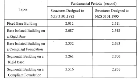
5.3 Fundamental Periods of Structures ... 82
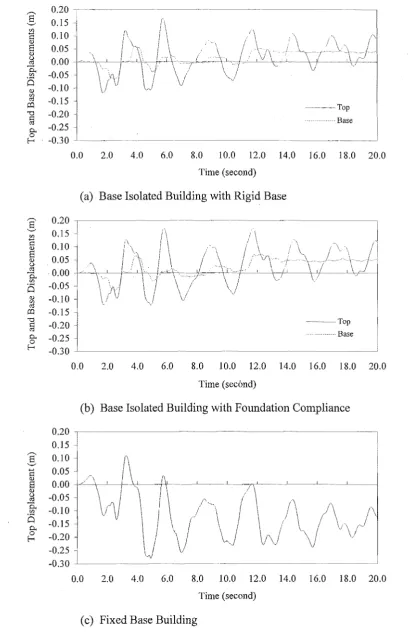
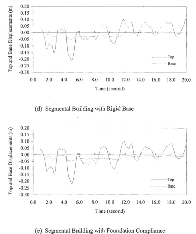
5.4 Seismic Performances of Base Isolated Structures and Other Types of Structures ... ... ... ... ... ... ... ... 85
5.4.1 Lateral Storey Displacements and Interstorey Drifts ... 85
5.4.2 Total Acceleration ... 88
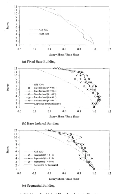
5.4.3 Base Shears and Lateral Storey Shear Envelopes ... 101
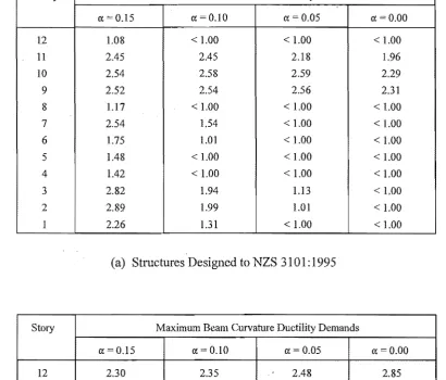
5.5 Curvature Ductility Demands of Beams and Columns ... 110
5.6 Summary and Conclusion ... 111
CHAPTER 6 THE SEISMIC RESPONSES OF STRUCTURES WITH ADDED DAMPING DEVICES SUBJECTED TO THE 1940 EL CENTRO N-S EARTHQUAKE 6.1 Introduction... 115
6.2 Additional Equivalent Viscous Damping Used in This Study... 116
6.2.1 General ... 116
6.2.2 Loading Time History ... 116
6.2.3 Determination of Effective Period ... 117
6.2.4 Determination of Effective Damping ... 119
6.3 Seismic Performances of Structures with Additional Damping ... 133
6.3.1 General ... 133
6.3.2 Lateral Storey Displacements and Interstorey Drifts ... 133
6.3.3 Total Acceleration ... 145
6.3.4 Base Shears and Lateral Storey Shear Envelopes ... 145
6.4 Curvature Ductility Demands of Beams and Columns ... 158
6.5 Summary and Conclusion ... ... ... ... ... 161
CHAPTER 7 EFFECTS OF DIFFERENT EARTHQUAKES ON THE SEISMIC RESPONSES OF STRUCTURES 7.1 Introduction... 164
7.2 Scaled Earthquake Records ... 165
7'.2.1 General ... , 165
7.2.2 Scale Factors Used in This Study... 165
7.3 Overall Response Quantities of Structures . ... ... 169
7.3.1 General ... 169
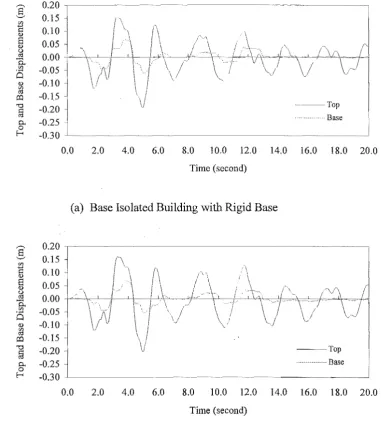
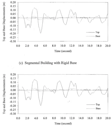
7.3.2 Top and Base Floor Displacements ... ... ... ... 173
7.3.3 Lateral Storey Displacements and Interstorey Drifts ... 179
7.3.4 Base Shears ... 194
7.5 Summary and Conclusion ... 209
CHAPTER 8 CONSIDERATIONS FOR THE ANALYSIS AND DESIGN OF BASE ISOLATED AND SEGMENTAL STRUCTURES 8.1 Introduction ... 213
8.2 Proposed Design Procedure ... 213
8.3 Example ... 218
8.4 Summary and Conclusion ... 221
CHAPTER 9 SUMMARY AND CONCLUSIONS 9.1 SuInmary... 222
9.2 Conclusions ... 224
9.3 Recommendations for Further Research ... 227
REFERENCES ... ... ... .... ... .... ... ... ... ... ... ... .... .... ... 229
APPENDIX A SEISMIC PERFORMANCES OF STRUCTURES DESIGNED TO NZS 3101:1982 UNDER THE EL CENTRO 1940 N-S EARTHQUAKE ... 238
APPENDIX B SEISMIC PERFORMANCES OF STRUCTURES WITH ADDITIONAL DAMPING WHEN DESIGNED TO NZS 3101:1982 UNDER THE EL CENTRO 1940 N-S EARTHQUAKE ... 246
APPENDIX C OVERALL RESPONSE QUANTITIES OF STRUCTURES DESIGNED TO NZS 3101:1982 UNDER THE FOUR SCALED EARTHQUAKE RECORDS ... ... 254
APPENDIX D INPUT DATA FOR COMPUTER ANALYSES ... ... 285
APPENDIX E UNIFORM MODELS ... 297
<lo
b
c
g
h
k
~in ko
kv,emb
ky,sur
kv,tre
kx,emb
ky,emb
p
r
t
u
U
ii
NOTATIONS
dimensionless frequency
= maximum horizontal dimension of the building
= cohesion of soil
dimensionless dynamic damping coefficient of the vibration mode frequency, shape and embedment front coefficient of horizontal damping
= frequency, shape and embedment side coefficient of horizontal damping
= frequency and shape dependent coefficient of horizontal damping in x-direction frequency and shape dependent coefficient of horizontal damping in y-direction
= frequency and shape dependent coefficient of vertical damping
= design eccentricity acceleration of gravity
distance from the mid-height of the sidewall to the ground surface
= height of ith floor.
= mode index
dimensionless dynamic stiffuess coefficient of the vibration mode
= effective stiffuess of base isolation system
= maximum effective stiffness of base isolation system minimum effective stiffness of base isolation system initial or elastic stiffuess
= dynamic vertical stiffuess coefficient of embedded foundation
= dynamic vertical stiffness coefficient of surface foundation dynamic vertical stiffness coefficient of trench foundation dynamic horizontal stiffness coefficient in x-direction
= dynamic horizontal stiffness coefficient in y-direction
= exponent used in the Code-Type approach fonnula for predicting the
equivalent lateral force distribution
=
displacement of a degree-of-freedom due to a unit ground displacement= ratio of elastic stiffness to post-yield stiffness ofthe bilinear model time
relative displacement = relative velocity
= relative acceleration
u
g ground velocityu
g ground accelerationv = total-motion displacement
v
= total-motion velocityv
total-motion accelerationy = total displacement of the system
Yo = displacement of the lower layer of the system
YI = displacement of the upper layer of the system
Ab base area of footing foundation
As = soil-sidewall contact area of embedded foundation
Aw = effective soil-sidewall contact area of embedded foundation
Aws soil contact area of sidewall which is parallel with horizontal motion
Awce soil contact area of sidewall which is perpendicular with horizontal motion
B = damping coefficient corresponds to the damping value in percentage of
critical damping
one-half of footing width
C = damping matrix
Ceff
Ceq
Ch (Tl' /l)
C
v= radiation damping coefficient
= basic seismic coefficient (NZS 4203: 1976) lateral force coefficient (NZS 4203: 1992)
= damping coefficient for a base isolation system
= horizontal damping coefficient due to foundation base
horizontal damping coefficient due to foundation base in x-direction horizontal damping coefficient due to foundation base in y-direction
= seismic coefficient (NZS 4203: 1976) = dynamic seismic coefficient
additional equivalent viscous damping coefficient
= equivalent soil-foundation damping coefficient
= basic seismic hazard acceleration coefficient vertical damping coefficient of soil-foundation horizontal damping coefficient due to sidewall
= damping coefficient for the lower layer of the soil-foundation = damping coefficient for the upper layer of the soil-foundation
depth of embedment
D minimum lateral seismic displacement
DT total design displacement
DlM = total maximum displacement
Eh = additional hysteretic damping of the base isolated structure
Fi equivalent static lateral force at ith floor
Fy yield strength or yield force
F y
=
maximum positive yield forceF y- = maximum negative yield force
F+ maximum positive force
F- maximum negative force
G
=
soil shear modulusGem = complex soil shear modulus
Gmax maximum soil shear modulus
Go = soil shear modulus at ground surface
. G1 = apparent soil shear modulus
I
=
importance factor (NZS 4203:1976)K
Kb
Kbl
Kb2
KB
Kd
Ks
Keq
Kdv,emb
Ksv,emb
Kdx,emb
Kdy,emb
Ksx,emb
Ksy,emb
degree of isolation given by TiT 1 (U)
=
coefficient of trench effect= coefficient of sidewall effect
= stiffness matrix
stiffness of linear isolator
=
initial or elastic stiffness of bilinear isolator= post-yield or plastic stiffness of bilinear isolator
effective or secant stiffness of bilinear isolator
= dynamic stiffness of the dynamic impedance of soil-foundation
= static stiffness of the dynamic impedance of soil-foundation
=
equivalent soil-foundation stiffness coefficientlower soil-found stiffness coefficient
=
upper soil-found stiffness coefficient= dynamic vertical stiffness of embedded foundation
static vertical stiffness of embedded foundation
dynamic horizontal stiffness of embedded foundation in x-direction
= dynamic horizontal stiffness of embedded foundation in y-direction
=
static horizontal stiffness of embedded foundation in x-directionstatic horizontal stiffness of embedded foundation in y-direction
Ksx,sur = static horizontal stiffness of surface foundation in x-direction
Ksy,sur static horizontal stiffness of surface foundation in y-direction
L one-half of foundation length
Lu = limit state factor (NZS 4203: 1992)
M = structural material factor (NZS 4203:1976)
N
NL
P
pet)
Po
PI
PFj Qy
Q/W
R
S
SA(T,()
Sb
SD (T ,()
Sp
Sy
Sz
total mass of structure mass matrix
= near-field coefficient proximity to active faults = non-linearity factor
axial load
applied load relating to the ith displacement mode = time varying loading on the structure
axial load for lower layer of soil-foundation axial load for upper layer of soil-foundation
.::::= participation factor for ith mode
= yield force at yield displacement
= ratio of yield force to weight of bilinear isolator
seismic risk factor (NZS 4203: 1976 or NZS 4203: 1992) = hysteretic loop ratio
= ductility factor of the superstructure for conventional structure force reduction coefficient
= structural type factor (NZS 4203:1976)
=
site coefficient based on soil profile= spectral absolute acceleration for period T and damping ( maximum base shear
= spectral relative displacement for period T and damping ( = structural performance factor (NZS 4203:1992)
= shape dependent coefficient of soil-foundation horizontal stiffness vertical static stiffness parameter
= natural period of the isolated structure
= natural period of linear base isolator period in elastic region of bilinear isolator period in plastic region of bilinear isolator
=
effective period for bilinear isolatorTclf effective period of the structure
1'( = fundamental period of vibration for the direction being considered
TJ elf = effective fundamental period
l' ( (U) unisolated undamped first mode period
TJ (U1) fundamental period of un isolated structure
V = base shear
Vb = minimum shear force below the isolation system
V s minimum shear force above the isolation system
= shear wave velocity
V ce = compression extension wave velocity
V La Lysmer's analog wave velocity
V s, m shear wave velocity taking into account of the effect of soil material damping
W = total dead weight of the structure (NZS 4203: 1976)
= total weight of structure
W d work done for the energy dissipated at the peak displacement
Wi portion of the total weight located at level i
=total gravity 10ad(NZS 4203:1976)
Wt
=
total seismic weight of the structure (NZS 4203:1992)Xb maximum relative base displacement of isolated structure
Xmax = maximum peak horizontal displacement
Y = modal amplitude
Yi = modal amplitude at ith mode
Z seismic zone factor (NZS 4203:1992)
ex
ratio of elastic stiffness to post-yield stiffness of the bilinear model= a constant related to the mass matrix in Rayleigh's damping model
~ a constant related to the stiffness matrix in Rayleigh's damping model
Llmax maximum design displacement
Ll + = corresponding maximum positive test displacement
Ll- = corresponding maximum negative test displacement
(b velocity-damping factor for isolator
(b2 velocity-damping factor in plastic region of bilinear isolator
(B = effective damping factor of bilinear isolator
(11 hysteretic damping factor of bilinear isolator
(v viscous damping factor of bilinear isolator
A
= minimum effective damping of the base isolated structureAeff additional damping ratio
A1 cff = effective equivalent viscous damping of mode 1
~L ratio of maximum displacement to the yield displacement of base
isolation system
= structural ductility (NZS 4203: 1992)
v = soil Poisson's ratio
~m damping ratio effect of soil material damping
rc 3.1415926
p = soil mass density
¢
= angle of internal frictionmodal matrix
{ ¢ }
i ith mode of free vibrationW = natural frequency of structure
weff = effective circular frequency of the structure
Wi ith frequency of free vibration
ATC
DIS
EERl
NZNSEE
PTFE
RMS
SEAOC
SEAONC
SRSS
UBC
ABBREVIATIONS
= Applied Technology Council
Dynamic Isolation Systems
= Earthquake Engineering Research Institute
= New Zealand National Society for Earthquake Engineering
= Polytetrafluoroethylene
Root-Mean-Square
= Structural Engineers Association of California
= Structural Engineers Association of Northern California
Square Root of the Sum of the Squares
= Uniform Building Code
CHAPTER 1
INTRODUCTION
1.1 General
Recent earthquakes, particularly the 1989 Lorna Prieta [E2] and 1994 Northridge [E3]
earthquakes in California, and the 1995 Kobe [Kl] earthquake in Japan, have caused significant
loss of life and severe damage to property. Many aseismic construction designs and technologies
have been developed over the years in attempts to mitigate the effects of earthquakes on buildings
and their vulnerable contents. Attenuating the effects of severe ground motions on the buildings
and their contents is always one of the most popular topics in the area of civil and structural
engineering and attracts the attention of many researchers and engineers around the world.
The technique of base isolation has been developed in an attempt to mitigate the effects
on buildings and their contents during earthquake attacks and has been proven to be one of the
more effective methods for a wide range of seismic design problems on buildings in the past two
decades. Seismic isolation consists essentially of the installation of mechanisms which decouple
the structures and their contents from potentially damaging earthquake-induced ground motions.
This decoupling is achieved by increasing the flexibility 'of the systems, together with providing
appropriate damping. Careful studies have been made of structures for which seismic isolation
may find widespread application. This has been found to include common forms of new and
existing multistorey building structures.
In seismic isolation, the fundamental aim is to reduce substantially the transmission of the
earthquake forces and energy into the structure. This is achieved by mounting the structure on
an isolation system with considerable horizontal flexibility so that during an earthquake, when
the ground vibrates strongly under the structure, only moderate motions are induced within the
structure itself. As the isolator flexibility increases, movements of the structure relative to the
ground may become a problem under other vibrational loads applied above the level of the
isolator,particularly wind loads. Skinner et al (1993) [S6] indicated that a base isolator with
hysteretic force-displacement characteristics can provide the desired properties of isolator
flexibility, high damping and force limitation under horizontal earthquake loads, together with
high stiffness under smaller horizontal loads to limit wind-induced motions.
Kelly (1990) [K2] gave a brief introduction to the response mechanisms of base isolated
buildings through a two degrees of freedom linear system. The effectiveness of the isolation system to mitigate the seismic response is through its ability to shift the fundamental frequency
of the system out of the range of frequencies where the earthquake is strongest. Also, Skinner et al (1993) demonstrated that the most important feature of seismic isolation is that its increased
flexibility increases the natural period of the structure. Because the period is increased beyond
that of the earthquake, resonance is avoided and the seismic acceleration response is reduced.
The successful base isolation of a building depends on the installation of mechanisms which decouple the structure from potentially damaging earthquake-induced ground motions.
Therefore, it is very important to have an adequate understanding of the influence of each
parameter in the isolation system and the superstructure on the seismic performance of the base isolated buildings. The primary function of an isolation device is to support the superstructure
while providing a high degree of horizontal flexibility. This gives the overall structure a long
effective period and hence lower earthquake generated accelerations and inertia forces. Many
kinds of isolation systems have been developed to achieve this function, such as laminated
elastomeric rubber bearings, lead-rubber bearings, yielding steel devices, friction devices (PTFE
sliding bearings) and lead extrusion devices, etc ..
Andriono (1990) [A2] indicated that base isolated structures have the ability to
significantly reduce the ductility demands in the superstructure compared with those of
unisolated structures. This makes possible simplification of the structural detailing and other
seismic design considerations required by the more conventional approaches. Therefore, a wider
choice of architectural forms and structural materials is available to the designer.
Besides the technical feasibility, another key issue that must be addressed early in the
design phase of a base isolated building is the economic feasibility. In terms of economic cost,
four principal factors should be evaluated. Kelly (1990) indicated that these are construction
3
seismic isolation techniques may often reduce the cost of providing a given level of earthquake
resistance to buildings.
In the past two decades, base isolation has become an increasingly accepted technique for
providing earthquake protection to buildings and their contents. On the other hand, base isolation
has often been considered as a technique for problem structures or for equipment which requires a special seismic design approach. This may arise because of their function (sensitive or high
risk industrial or commercial facilities such as computer systems or nuclear power plants); their
special importance after an earthquake (hospitals, disaster control centres such as police stations);
poor ground conditions (proximity to a major fault); or other special problems (increasing the
seismic resistance of existing structures) as described by Skinner et al (1993).
Therefore, seismic isolation does indeed have particular advantages over other approaches
in these special circumstances, usually being able to provide much better protection under
extreme earthquake motions. It is believed that seismic isolation may be used to provide
effective solutions for a wide range of seismic design problems.
1.2 Objectives of the Research
Several practical techniques for achieving seismic isolation and a variety of
energy-dissipating devices have been developed and implemented around the world in recent years.
Most practical work still relies upon a series of deterministic dynamic inelastic time history
analyses [B5,C5]. The primary aim of this research is to give a better understanding of the
behaviour of the base isolated buildings and a greater confidence in the behaviour of
substructures under the most credible ground excitation. On the other hand, the results of
analysing buildings using time history analyses subjected to the different earthquakes will be
compared with those of the buildings designed to excitation associated with the response spectra
found in New Zealand and other overseas building codes.
The first objective of this research is to investigate the seismic responses for stiff and
flexible 12-storey buildings designed to New Zealand Standard Code of Practice for Design of "
Concrete Structures NZS 3101:1982 [N1] and NZS 3101:1995 [S9] to the different isolation
Also, it seeks to evaluate the effect of using a segmental building proposed by Cui (1995) [C13]
where the isolation devices are placed at various levels in the building in order to reduce the displacements imposed on each of the devices.
Usually the increase of added viscous damping in a structure may reduce the displacement
and acceleration responses of the structure. Thus, the second objective of this research is to
ascertain the effects of added viscous damping based on the equivalent static method
recommended by New Zealand Standard Code of Practice for General Structural Design and Design Loadings for Buildings NZS 4203: 1992 [S8] and then to investigate the seismic responses
of the stiff and flexible buildings which will be compared with those of the structures without
additional damping for different earthquake motions.
1.3 Scope and Outline of the Thesis
This research seeks to present a development of theoretical and analytical aspects of the
behaviour of base isolated buildings. The following outline describes the scope ofthe study. To
evaluate the development, the results and the proper selection for further research on base
isolated structures, a review of the current design methods and existing design codes are
presented in Chapter 2. The principles of dynamic analysis, structure modelling and soil-footing
foundation impedance are discussed in Chapter 3. The procedures of the analyses of the base
isolated structures are outlined in Chapter 4. This chapter involves soil site model related,
comparison of earthquake and wind loads, selection of base isolators, dynamic parameters of the
base isolated buildings, earthquake excitations and the methods used in the analyses.
Chapter 5 presents the seismic responses of base isolated buildings subjected to the EI
Centro N-S earthquake which is commonly considered as a standard and on which many codes
have been historically based. In this chapter, the seismic responses of base isolated structures
with elasto-plastic and bilinear isolation devices are investigated and compared with those of
other types of structures such as fixed base and segmental buildings. Some discussion of
curvature ductility demands of beams and columns in the frames are also presented.
The seismic responses of different types of structures including base isolated, fixed base
5
presented in Chapter 6. This chapter includes equivalent viscous damping calculated by the
loading time history, dynamic responses of different structures with additional damping and comparison with those of structures without added damping and some discussion of curvature
ductility demands of beams and columns for different types of buildings.
Effects of the ground motion characteristics on the structural behaviour of base isolated
multi storey buildings are studied in order to be able to select the right system for a particular type of ground motion so that the base isolation device will provide a guaranteed benefit. A range of
earthquake records other than the N-S component of the El Centro 1940 are used as the basis of
these analyses. The chosen earthquake records were scaled according to their 5% damped spectra
to fit the design spectrum in Section 4.6.2.9 (b) (ii) ofNZS 4203:1992 code for the intermediate
soil sites. The results of this investigation are reported in Chapter 7.
discussed in chapters 5, 6 and 7, the buildings used were based on two different design
standards. One building was designed to NZS 3101: 1982 and the second one was designed to
NZS 3101: 1995, and in accordance with the provisions of loading code NZS 4203: 1992.
Chapter 8 presents a consideration for the analysis and design of the base isolated and
segmental buildings. In this chapter, a basic concept o.f the preliminary design choice enables
the designer a better understanding ofthe design for the base isolated and segmental buildings.
This chapter includes a proposed design procedure and example to explain the design of the base
isolated and segmental structures.
Finally, some conclusions and recomnlendations for further research on base isolated and
REVIEW OF CURRENT DESIGN METHODS AND
CODES FOR BASE ISOLATED STRUCTURES
2.1 Introduction
Many studies since the early 1970s have discussed and considered seismic isolation
devices of various types of structures. These include performance of structures with their
isolation systems in earthquakes, various kinds of isolation systems and the experimental studies on their performance, earthquake simulator tests of model structures mounted on isolation
devices and computer studies of the response of simulated structures with isolation systems.
Seismic base isolation reduces the response accelerations at the expense of relatively large base
displacements when compared to conventional buildings and the analytical model of the isolation
system plays an important role in the dynamic analysis of base isolated buildings, as it has a
significant influence on the accuracy of the analysis results.
The concept of introducing isolation systems to mitigate seismic effects is a well-known technique and the development of many practical base isolation devices was accompanied by
proposed design methods for base isolated structures. Ah equivalent linear analysis was used by
most proposed design methods for approximating the inelastic behaviour of the base isolation
systems as it affects the response of the elastic superstructure. The main purpose of these
methods was to assist the designers to design the isolated structures without depending on a series of deterministic inelastic time history analyses. In the following, several design methods
and codes are reviewed from the numerous designs of base isolation systems.
2.2 Design Methods
2.2.1 Priestley, Crosbie and Carr (1977) [C12,P7]
This research work was carried out to study the seismic performance of four, eight and
twelve storey masonry shear walls mounted on base isolation devices. The main purpose of this
7
study was to examine an alternative method of limiting the inertia forces in masonry buildings
by seismic base isolation and also gave a significant contribution towards later attempts made
to investigate the seismic response of base isolated multi storey structures. They used a series of
deterministic time history analyses with earthquakes EI Centro 1940 N-S, Taft 1952 N69W, and two artificial Al and B 1 accelerograms generated by Jennings [11].
An equal-acceleration approximation for floor masses as suggested earlier by Skinner and
McVerry [S4] using a single degree of freedom model was found to be inadequate in this
research work. The distribution of the maximum base shear in proportion to floor mass resulted
in a severe underestimation of the required moment capacity of the four and eight storey masonry walls, and produced an envelope for the twelve storey wall which is conservative near the base
of the wall but non-conservative higher up the wall due to the influence of higher mode effects.
Priestleyet al [C 12,P7] proposed a tentative design recommendation regarding the lateral inertia
force distribution as follows:
1. The design lateral force should be found by distributing the base shear force V in
accordance withNZS 4203:1976 [C9], as expressed in Eq. 2.l, with an additional
O.2V applied at the roof level to cover the inertia force distribution resulting from
higher modes.
W.h.
F. :::: V I I
I LW.h.
I I
(2.1)
where Fi is the equivalent static lateral force at ith floor, Wi and hi are the total
gravity load and the height of ith floor respectively. An additional 0.2V to the
roof storey effectively increased the shear envelope at all levels by 20% of the
base shear.
(2.2)
in which
where V is the base shear, W is the total dead weight of the building, C,I,S,M,R
,
are the basic seismic coefficient, the importance factor, the structural type factor,
the structural material factor and the seismic risk factor respectively. In general, this would imply Cd equal to C based on the fact that S and M may both be set
equal to unity because structural yield is avoided.
2. Crosbie [C12] proposed some reduced values of C, for each type of base isolation
system considered, which should be used for determining the design forces in
base isolated masonry structures. This was based on the results obtained from the
above mentioned series of time history analyses. For example, the reduction of the basic seismic coefficient C from 0.288g to 0.160g would be recommended for
the design of squat masonry shear walls mounted on base isolation systems with lead energy dissipators and located in the seismic Zone A [C9].
It should be emphasized that the above recommendations were based on a limited case
study for certain types of structure and base isolation devices. It was found that this design
requirement would provide an adequate flexural and shear capacity for short to intermediate
period masonry shear walls (fundamental period less than 1.0 second). Further, it did not
explicitly show the correlation between the capacity of the base isolation system in providing
lateral flexibility and additional hysteretic damping and the structural response. Such correlation
is essential to give the designers a clear understanding of how the base isolation system reduces
the seismic forces within the structure.
2.2.2 DIS, Inc.'s Design Procedures for Buildings
Mounted on Lead-Rubber Bearings (1984) [D5,M2]
These design procedures for buildings mounted on lead-rubber bearings were developed
by a California based consultancy fInn, Dynamic Isolation Systems (DIS), Inc .. The design procedures using a series of charts have been developed for ATC-3 [AS] seismic region
maximum credible earthquakes with acceleration coefficients in the range of 0.20g to OAOg for
all soil types. Also included, are curves based on the Caltrans design spectra. The procedures
are based on a single-degree-of-freedom representation of the building. It was stated in this
9
and the building is reasonably symmetric, the single-degree-of-freedom assumption is a good approximation for design purposes.
The inelastic response of a multistorey building is approximately predicted in these design
procedures by the pseudo elastic response of its fundamental mode. No specific guidance was given for the lateral force distribution up the height of the superstructure. Some modification had
been conducted to transform these inelastic response spectra approaches into a number of design
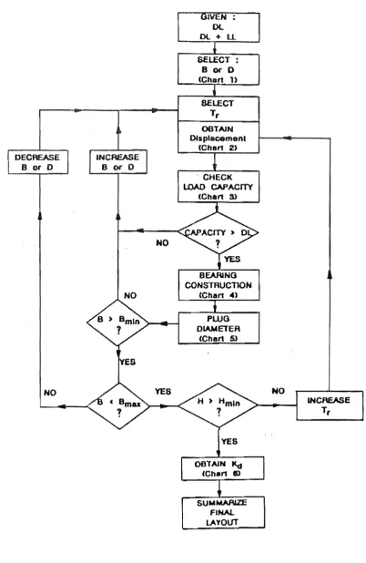
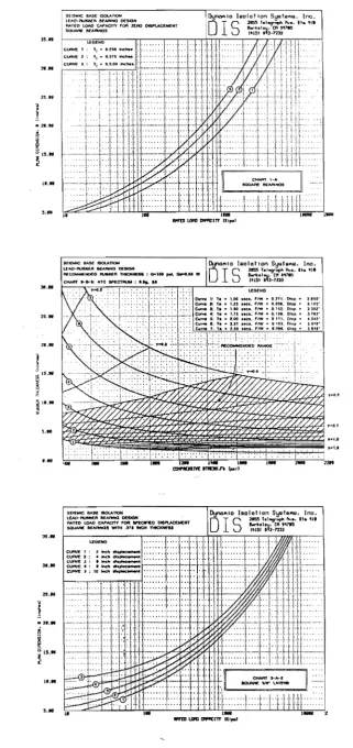
charts in a format considered by DIS as suitable for design use. Fig. 2.1 shows a flow chart to
illustrate the step-by-step design method and Fig. 2.2 shows charts of each series used in this design procedure.
1. Assemble required data.
Summarize the bearing location, the dead load and the dead plus live load for
each bearing position. The dead load should include seismic live load.
2. Select plan dimension.
From chart series 1 select the appropriate curve for the selected plan shape and
internal rubber layer thickness.
3. Select rubber thickness.
Using the total dead load and total area of all bearings compute the average
compressive stress on all bearings. Select the appropriate graph from chart series
2 for the site acceleration level and soil conditions. Select a rubber thickness
appropriate to the degree of isolation desired. Obtain the force coefficient and
displacement by interpolation between the curves provided.
4. Check load capacity.
DECREASE
B or D
NO
INCREASE
B Of D
NO
NO
I N :
DL
Ol+LL
SELECT: B Of D
(Chan U
SELECT
Tr
OOTAJN
Otaplacement
(Chan 2)
CHECK
lOAD CAPACITY
(Chan 3)
B~NG
CONS"fRUCTJON (Chan .. )
PWG
DIAMETER
(Chart 5)
YES
NO
INCREASE
Tr
[image:23.563.92.495.80.699.2]i AATfO la..-.o f;JI,PAt:;nV ,~ nRC) DIBI"l..ACllitfJff ' lIo;woi! I en 'tII1tI5
, S{I!U.II(; BASE: ISOt..ArlOtt Of"k')AIO laolot Ion SBBfal'u'I. Inc ..
: lE"O~RU&a£A etAAlHQ OfS.I()ff
I S
l1JS$ r.1~ ".,. •• It .. 'III ~ MAJllHOS i 1'15; :~i-rm
]5." ~'O~~'N~O---~'---.--'~-'-rt."---'--~'-'-TTTT'---~
JI ...
...
~
i
• It,"
I
0' 15 ..~ .
111 ...
....
lB."
25."
211."
J
; J$ . •
~ fc
~ II."
~
....
....
>S ...
3 ....
n ...
. ,
j
. 2 ....
!
i
IS."I ....
....
I '
'1 .. (lUO~.
',.o.:"!J~
-
- _
...
,".1 . .0 .,...',1
SEi9WC 8A3E molATlON
l..EAV-~A M.u.HQ DE8J()JoI
MUD lOAD CAl"ACfTY FOR ~ ~WEHT
!K)U.oVlf MAAH<l!J wrTH .J'" IIfCH ~
t£O£NO
CtJR'Yf'l::Iroc:h~, ••• , • • • • • •
(:~t!.Ir\odI~ ••••••• , ••••
c\.IRYEJ!'IrIdt~
QJfW'E I • 10 foodt ~
o..ro~IO h.olol'on S~.I ... lno.
O I S
~hl~r... •• Ct.41'~r';~3_~~~m
Fig. 2.2 The Series of DIS Design Charts
[image:24.563.96.418.52.734.2]~ ,.
~
~
u
i:
~ ~
OCeAnia C9H!lIf\UCI(w ton QMH fMJMra IHiGKH.l!!.I1
I.S 1
...
'ij
,. " c
" Q
~
..
'"
2
\I)
'"
Uj
~
~
,
..
.
"
.'"
"'"
'8
38
24
If
0
:10 100
SEIS""~ BASE IS()lA nQH lEAQ.. AU8BER 8e",RlJtKj OESIGN P()$1-ElASnc STlFFNESS SOUAPIE 8E.AR1HQ5
Fig. 2.2 ... (continued)
10 II
[image:25.563.119.415.102.720.2]13
displacement from step 3, obtain the maximum allowable load under earthquake
loading. Compare this with the maximum dead load plus seismic live load plus
earthquake induced axial load on the bearing. If the load capacity is less than
applied load, the plan dimension must be increased or the rubber layer thickness
decreased. Repeat from step 3 for the new average compressive stress.
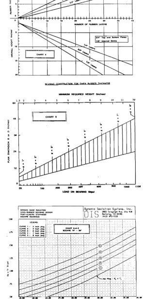
5. Determine bearing construction.
From chart 4 determine the number of rubber layers and total height for the
required rubber thickness.
6. Obtain lead plug diameter.
From chart 5 obtain the lead plug diameter required for the dead load on the
bearing. Check that the plan dimension is-greater than the minimum and less than
the maximum. If not, decrease or increase the plan size, recalculate the
compressive stress and return to step 3. Check that the overall height is greater
than the minimum. If not, increase the rubber thickness and return to step 3.
7. Check overall bearing dimensions.
If the dimensions are satisfactory, check that any constraints imposed by the
bearing layout are met. Adjust the bearing size if necessary.
8. Obtain post-elastic stiffness.
From chart series 6 obtain the value of kd for each bearing for the selected plan
dimension, lead plug size and rubber thickness.
9. Summarize final layout.
Summarize the final bearing size, construction and plug diameters for the final
It appears that this design procedure is aimed more for designing the lead-rubber bearings
and their placements on site rather than for designing the whole structure. Hence, it was presented more as a design manual rather than providing the designer with a clear insight of the
seismic behaviour of the structure or giving himlher a good feel of the sensitivity of the various parameters of base isolation system associated with the seismic response.
2.2.3 Andriono and Carr (1990) [A2,A3,A4]
This study was carried out to investigate in more detail the effects of various structural
parameters and ground motion characteristics on the response of base isolated multi storey
structures. The results were then used to develop two simplified analysis methods for practical design. The first proposed method which is called the Code-Type approach [A2] can be used to accurately estimate the inertia forces, not only at the level of the base isolation devices but
throughout the entire height of the multistorey structure. This design procedure is suitable for
a preliminary design or even a final design of uniform base isolated multistorey structures with
an unisolated fundamental natural period, T1(UI} , less than approximately 0.8 seconds. The
second procedure, which is based on the Component Mode Synthesis method [A2], is suggested
for fmal design purposes of base isolated multi storey structures with more irregular andJor more
flexible superstructures.
The availability of these simple approximation methods means that inelastic time history analyses will no longer be necessary for practical design purposes. However, inelastic time
history analyses may still be required to evaluate the inelastic behaviour of the superstructure
under a very severe earthquake in order to ensure that the superstructure will have a satisfactory
failure mechanism. The two design methods are briefly presented below.
a. Code-Type Approach
The proposed Code-Type approach is developed by adapting the well-known
equivalent static lateral force analysis procedure to suit the seismic behaviour of base isolated
multi storey structures. It was hoped that this similarity would help the designer to become
familiar with this proposed approach. Fig. 2.3 shows a flow chart to illustrate the step-by-step
Certain Requirements
e.g. mu.hor/z. dlspL
design wind load
Design Level E/Q (Spectral
Accelerations)
1. Determine T,{UO
SE
Un/so/.' ••~(FIXed
base)2. Make a trial selection
of. BI system
kO:: ?
(1 ::?
Fy ::?
3. Assume \.L:: Xmgx
Xy
4. Calculate
ke " of BI system
7. Calculate maximum
I--_ _ _ _ _ _ ~ • 81 system lateral force
• Base displacement
(I!o.'o)
9. Design the detailing of 81 system
NO
10. Calculate base shear & lateral
forces
11. Design the $uperstruc ture's
members
Fig. 2.3 Step-by-Step Design Procedure of the Code-Type Approach for Base Isolated Multistorey Structure
1. Detennine the fundamental period of the unisolated superstructure
T1(uI) •
This can be carried out as usual by assuming that the superstructure is not
mounted on a base isolation system. At a preliminary design stage the
approximate fonnulas as mentioned by some codes [ClO,D4,Rl,Tl] can
be used to estimate the fundamental period of this fixed base
superstructure.
2. Make a trial selection of the base isolation system.
The required reduction of lateral· inertia forces is nonnally the main
consideration for selecting or predicting the idealized bilinear hysteresis
loop parameters of a base isolation system, i.e. its initial stiffness, ko' its
post-yield stiffness, ako' and its yield strength, F y' Other requirements
such as the maximum allowable horizontal displacements at working
loads (due to wind and small earthquakes) and ultimate load levels
(stability of the base isolation system) should also be considered. For this
purpose a designer must know the design-level seismic load specified by
the code for the particular site where the structure will be built, as well as
the essential characteristics of a desirable base isolation system. The
designer must therefore make an initial selection of ko' a and F y •
3. Assume the maximum base displacement under the design-level
earthquake and calculate the so-called maximum displacement ductility
rati 0, I-lassumed'
4. Obtain the effective (secant) stiffness of the base isolation system at the
maximum base displacement by using Eq. 2.4 or from the chart shown in
Fig. 2.4.
k (l-a + a)
0.7
.:P 0.6 ·S ...
~ 0.5
IJJ
<:
tt
0.1.h: V)
~ 0.3
h:
(.) 0.2
If
ffi
0.10 2
Nole:
kc-ff =ko ('~o.
..
a)
0.
---025
---0..20
- - - 0 . 1 5
---0.10
---0.05
6 10 11. 18 22 26 30
~ = xm<X1l/Xy
Fig. 2.4 Effective Stiffness of Base Isolation Systems
with Bilinear Hysteresis Loop Model
"0 Note: Ad~.). :t ~ (t -a.) (~)
e,
.!;!
Z3 1.0 O.~R" ~<1.0
~
I I~ __ .JW,
"-I!) 35 0.55 <:
it
0.1.7
:t 30
C3
~ 25 0.39 a.
0.05
0
u
V) 20
s:: 0.31
::.:
~ 15 0..23
0.10
~
....J 10 0.16
0.15
~ 0 0.20
0.08 0..25
i::: 5
8
"l:0 0
2 6 10 11. 18 22 26 30
11 " )(rncz /)(y
Fig. 2.5 Additional Damping of Base Isolation Systems
with Bilinear Hysteresis Loop Model
5. Determine the increase in damping due to the hysteretic behaviour ofthe
base isolation system using Eqs. 2.5 and 2.6 or from the chart shown in
Fig. 2.5. Then calculate the effective damping of the structure as the sum of the inherent damping of the structure and this additional hysteretic
damping.
(2.5)
_ Jl-I ko
R (Ia) ( )
-Jl2 keff
(2.6)
In this study R is called the hysteresis loop ratio~ i.e. the ratio of the
hysteresis loop area to the area of the circumscribing rectangle. This
value will be used further in step 10.
6. Determine the effective fundamental period of the base isolated
multistorey structure from the chart shown in Fig. 2.6. Note that this
chart is developed for base isolated multi storey structures with uniform
floor mass and interstorey stiffness. Charts for other variations of floor
mass and interstorey stiffness may be developed later. In the absence of
such charts a proper modal analysis should be conducted to calculate the
effective fundamental period of the base isolated structure.
7. Based on the effective fundamental period and damping of the structure
determine the maximum shear force of the base isolated structure from
the appropriate acceleration spectra specified by the New Zealand loading
code. Then calculate the maximum base displacement and the maximum
displacement ductility ratio, !!calc'
8. Compare the calculated maximum displacement ductility ratio, !!calc with
the maximum displacement ductility ratio, Ilassumed assumed in step 3.
If the difference between these two values is relatively great, say above
OJ ::..
...
-. -... u
~
OJ~
-OJ t-::;-.
...:-12
kefrfw/m
J
10
8
6
4
2
0.8_
12-2.4
2.8
3.2_
3.6_
4.0_
5.0_
Fundamental Period#
1iruI/secs}
Fig. 2.6 Effective Fundamental Period of Uniform Base Isolated Multistorey Structures
displacement ductility ratio may be used as a new assumed value until the
two values converge. The convergence in the trial and error process is
normally achieved very rapidly. Then the design process can be
continued to step 9.
9. Design the details of the base isolation system.
Experimental data on tests of base isolation devices and design manuals for bearings can be used as a guidance to design the selected base
isolation system in detaiL
10. Determine the equivalent static lateral force distribution over the entire
height of the multi storey structure.
The equivalent static lateral force, Fi at floor i can be accurately predicted
by the following formula:
W. h.P Fi = V __ I _ I _
I:
W. h.1 1 P (2.7)where V is the base shear, Wi and hi are the weight and height of floor i
respectively. The exponent p can be determined from the strong linear
correlation with the hysteresis loop ratio of the base isolation system
shown in Fig. 2.7. A modification factor, as shown in Fig. 2.8, should
also be used to obtain the maximum value of the base shear of the
superstructure from the shear force of base isolation system.
11. Design the members of the superstructure.
Once the lateral forces are satisfactorily determined the member forces in
the structure can be computed and the members of the superstructure can
5.0
Q.. 1..0
DZ 4203 Zone A
Normal Soils
Shear-beam (p:::CD)
Cantilever (
p
.:0 )-
c:
CI.l
c:
3.0~
Q.
~
-
c:
Q.l
§.
~
2.0
1.0
Hysteresis Loop Ratio I R
(a)
DZI.203 Zone A
Soft Soils
5.0 Shear-beam
(p.:ooJ
- - - Cantilever (p:::O)
4.0
3.0
2.0
1.0
o
L-~~~__
- L _ _ ~ _ _ ~ _ _ ~~ . . _o
U2
Hysteresis Loop Ratio. R
~
I _ _ .J - I(b)
Fig. 2.7 Relationships between R and p for Different T, (UT) under
New Zealand Design-Level Earthquakes for Zone A
x (Shear Force of 81 Sys.J
1.2 1.0
~
~---o
RFig. 2.8, Modification Factors Used for Predicting the Maximum Base
Shear from the Base Isolation System's Maximum Shear Force
As in the use of the equivalent static lateral force procedure for norusolated
buildings, this Code-Type approach would be adequate for base isolated multi storey structures
which have a uniform property configuration in all storeys or floors. The results of the
investigation show that this simple approach can reliably predict the response of short to
medium-rise base isolated structures with Tl(UI) less ~an or equal to 0.8 seconds, with floor
masses which do not differ by more than 25% in adjacent floors and where the lateral storey stiffness do not differ by more than 25% in adjacent storeys.
b. Component Mode Synthesis Method
In the design of unisolated structures, analysis methods usmg the modal
superposition technique are normally employed if the equivalent static lateral force procedure is
not able to satisfactorily predict the structural response. In a similar way the Component Mode
Synthesis method was suggested as a means of analysis for more complex base isolated
multi storey structures. In brief, this method treats a base isolated multi storey structure as two
separate components, i.e. the superstructure and the base isolation system. The superstructure,
which is expected to remain elastic under the design-level earthquake, can now be considered as
a linear multi-degree-of-freedom system and the ordinary modal analysis procedure can
23
This scheme is still based on a step-by-step integration. However, since it is
normally appropriate to approximate the structural response by incorporating the first few significant modes this method requires less computational effort when compared with the
inelastic time history analysis. Further, the Component Mode Synthesis method gives the
designer clearer insight into the structural response by showing modal contributions. However,
it is desirable that this method should operate on the response spectrum analysis approach rather than the step-by-step integration.
2.2.4 Skinner, Robinson and McVerry (1993) [S6]
This work was a relatively extensive systematic study on the seismic responses of base
isolated buildings where the parameters of the structure and isolation systems were varied over
wide ranges. Both the seismic performance of linear structures on linear isolation systems and
of linear structures on non-linear isolation systems were investigated. In the non-linear analysis,
the bi-linear model was used to simulate the force-displacement relationship of the hysteretic
non-linear base isolation systems. A numerical analysis method was used to investigate the effect
of each parameter in the isolation systems on the seismic response of a base isolated building
subjected to the N-S component of the 1940 EI Centro earthquake.
It was found from this study that an early decision in the design of a seismically isolated
structure is to determine whether a linear or nonlinear isolation system is required. The selection
will be govemed partly by the nature of the design criteria. As discussed in Ref. S6, nonlinear
isolation systems can usually produce lower values of first-mode dominated response quantities, such as base shears and displacements, while linear systems are particularly effective at
suppressing higher frequency responses. The two design procedures proposed for the design of
isolated structures with linear and nonlinear isolators are briefly described below.
a. Design Procedure for Buildh)gs with Linear Isolation Systems
Standard modal analysis procedures can be used to estimate the design responses of linear isolation systems. Initial estimates of displacements and base shears can be obtained
As a fIrst approximation, the fundamental mode period, Tb, and damping factor, (b' of a system with a high degree of linear isolation can be obtained by treating the structure as rigid, where
Tb
2X~
Kb (2.8)
(b Cb
2 JM Kb (2.9)
and the isolator has stiffness Kb and damping coefficient Cb , and supports a total mass M. The
maximum base displacement Xb and base shear Sb can be computed from Eqs. 2.10 and 2.11.
(2.10)
(2.11)
b. Design Procedure for Buildings with Bilinear Isolation Systems
Design criteria will usually involve acceptable base shears and displacements, and
perhaps allowable shears at other levels of the structure and acceptable floor response spectra.
The estimation of the seismic response for a structure with bilinear hysteretic isolation may
proceed as below.
1. Select a trial isolation system.
For design to a scaled EI Centro type motion which gives base shear and
base displacement as a function of
Q/
W, for various periods Tbl and Tb2, provide the possible combinations of parameters which produce responsesmeeting the design criteria. Here,
Q/
W is the ratio of yield force of the isolator to the weight of the structure. The period Tbl and Tb2 relate to theelastic and post-yield stiffness Kbl and Kb2 respectively.
2. Take a trial value of the base displacement Xb for the specifIed earthquake
25
Calculate Sb' TB and (B from the hysteresis loop which is drawn for the
chosen values of Kbl> Kb2, Qy IW and ~. For an assumed ~ , the bilinear
loop gives the base shear Sb and ratio of base shear to the weight of the
structure Sb/W as
K
S =
Q
(1 - ~) + Kb2Xbb Y K
Q
y(1-W
bI
+
The effective stiffness is the secant stiffness
The equivalent linear period based on this stiffness is
_g_(_T_b2_2 _-_T_bl_2)
Q
y ] -~
TB
=
Tb2 [ 1 +4n2 Xb W
(2.12)
(2.13)
(2.14)
(2.15)
The equivalent viscous damping corresponding to the hysteretic damping
is (h, where
(2.16)
To obtain the total damping (B' the viscous damping (v must be added.
(v should be associated with a particular viscous damper coefficient Cb ,
which gives a fraction (b2 of critical viscous damping at period TB . The
corresponding fraction of critical viscous damping is (T BIT b2) (b2 . This
definition gives
T
r + B r "'h "'b2
3. Use the earthquake displacement spectrum to fmd SD (TB > (B)' which is assumed to correspond to Xb, and estimate Sb from the hysteresis loop.
This approximation assumes that the structural flexibility and damping
has little effect on the first mode period and damping, as the structure is
regarded as rigid to obtain TB and (B'
4. Check whether the base displacement and base shear of step 3 agree with
the assumed displacement and corresponding base shear of step 2. If
satisfactory convergence has not occurred, further iteration is required.
New values ofTB and (B can be calculated using the latest values ofXb
and Sb'
5. Check the final estimates of Xb and Sb with the design criteria. If the
values are not acceptable, or it is felt that improved values may be
possible, select a new trial isolation system.
6. Check the higher mode responses.
The elastic-phase isolation factor, I (KbJ ), and non-linearity factor, NL , are calculated as
(2.18)
(2.19)
where TJ (U) is the first mode period of the unisolated structure and (h is as given in step 2. Using these parameters and the curves shown in Ref.
S6 to estimate the ratios between the second and third-mode top-mass
accelerations and the first-mode top-mass acceleration.
7. Repeat the calculations for any other required earthquake motions and
27
accelerograms to confirm the results obtained with the spectra approach
for the equivalent linear system.
Based on this study, for a building with proprietary selected linear isolation systems,
the seismic response of the building is dominated by its fundamental mode. The second and
higher modes make only a minor contribution to the response. Increasing viscous damping in
the isolation system generally decreases the displacement response of the overall system, which
is mainly governed by the first mode response, but increases the importance of the high frequency
acceleration components. The earthquake attack on secondary systems of the structure may
increase significantly with increasing isolator damping because of the enhanced high frequency
response, although remaining less than in an unisolated structure.
2.2.5 Cui and Pan (1995) [C13,P1]
This research work was carried out to study the dynamic characteristics and seismic
performance of frame buildings deforming in a shear-like manner mounted on linear and
non-linear isolation systems. The deterministic and random responses of segmental buildings were
also discussed in this study. The analysis process took into account the superstructure flexibility,
base raft inertia as well as the interaction between the secondary system and the main structure.
Parametric studies were carried out to investigate the influence of each parameter in the isolation
system on the seismic response of both the base isolated buildings and their contents. In the
nonlinear analysis, the bilinear hysteretic model was used to simulate the force-displacement
relationship of the base isolation systems, and the statistical equivalent linearization method was
used to estimate the root-mean-square response of the systems subject to random excitations.
The following four topics were included in this study.
a. Dynamic Characteristics of Buildings with Linear Isolation Systems
Based on the base isolated models shown in Ref. Cl3, the combined effects of
superstructure flexibility and base raft inertia on the dynamic characteristics were investigated.
A series of parametric studies were carried out, and the effects of varying the stiffness and mass
mode response usually dominates the seismic response of a base isolated building, first-order solutions are obtained for the fundamental base isolated frequency and mode shape. For frame
buildings deforming in a shear-like manner mounted on linear isolation systems, the second and
higher modes have smaller participation factors when compared with the fundamental mode.
The effectiveness of seismic isolation in reducing the higher mode response, by deflecting the ground motion energy through the orthogonality property, is clearly demonstrated.
b. Seismic Response of Buildings with Bilinear Isolation Systems
The root-me an-square (RMS) responses of frame buildings deforming in a shear-like
manner mounted on bilinear seismic isolation systems subjected to random excitations were
calculated by using the statistical equivalent linearization method. Parametric studies were
carried out to investigate the effect of varying each parameter of the isolation system and
superstructure on the seismic response of the base isolated buildings. The parameters considered
were the initial and the post-yield isolated frequencies, the yield ratio is the ratio of the yield force to the total weight of a base isolated building, and the fundamental fixed base frequency
of the superstructure.
The main purpose was to produce plots of the RMS response of a base isolated
building mounted on a bilinear isolation system and excited by a random earthquake input as a
function of the parameters of the bilinear isolation system and superstructure. From the studies,
for a given set of system parameters, there is an optimal yield ratio which will minimize the base
shear or base displacement for a given earthquake input. It indicated that the effect of varying
superstructure flexibility on the base displacement and base shear was not significant. For frame
buildings deforming in a shear-like manner supported on a bilinear isolation system, a
single-degree-of-freedom model can produce a good approximation to the system.
c. Seismic Response of Secondary Systems
The response of secondary systems mounted inside a base isolated building is
different from that of the systems directly mounted on the ground as the floor accelerations differ
in severity and characteristics from the typical noise-like ground accelerations which generate
29
buildings with linear and bilinear isolators subjected to a random excitation were calculated using the statistical equivalent linearization method. The effect of varying isolator and structural
parameters on the response of the secondary system was investigated through parametric studies.
The parameters considered in the analysis were the initial and post-yield isolator stiffness, the yield ratio of the base isolator, the damping coefficient of extra viscous dampers in the base
isolator and the viscous damping of the superstructure and secondary systems.
Compared to the response in the fixed base buildings, the peak response of
secondary systems are generally reduced by using base isolation systems. The frequencies of the
first peaks of floor response spectra are close to the fundamental isolated frequency of the
supporting system. For buildings with linear isolation systems, increasing the viscous damping
of a secondary system can significantly reduce its response, when the natural frequency of the secondary system is close to the isolated frequency. Increasing the viscous damping in the
isolation system would also have a similar effect on the response of secondary systems. For
buildings with a bilinear isolation system, increasing the viscous damping of a secondary system significantly reduces the amplitude of floor response spectra. It noted that the viscous damping
in the superstructure may help to reduce the response of the secondary systems.
d. Seismic Response of Segmental Buildings
This research work presented a preliminary study on the seismic response of an
optimized segmental building. Both deterministic and random response analyses were carried
out. In the deterministic response analysis, the N-S component of the 1940 El Centro earthquake
ground motion is used as an earthquake input. In the random response analysis, the earthquake
process is modelled as a filtered white noise. The segmental building can be regarded as a base
isolated building, for which the superstructure is further divided into several segments
interconnected by additional vibrati