Large-range active load for dynamic motor testing
S. (Sander) Roodink
BSc Report
C
e
Dr.ir. J.F. Broenink
T.G. Broenink, MSc
Dr. N. Meratnia
July 2017
024RAM2017
Robotics and Mechatronics
EE-Math-CS
University of Twente
iii
Abstract
Before electro motors can be used in robots, the parameters of the motors should be known. This can be done by using the data sheet of the manufac-ture, but this is not always sufficient enough. So the best way to get to know the parameters is by testing the motor. The test setup should be designed and build in a proper way, so that the useful parameters can determined. Like, maximal speed, maximal torque, maximal temperature and a torque-speed curve. The setup is splitted in three parts, the electro motor, sensors and a load.
v
Contents
1 Introduction 1
2 Background information 3
2.1 Dynamometer for an electric motor . . . 3
2.2 Large range torque and angular velocity problems . . . 3
2.3 RAPID: an inexpensive open source dynamometer for robotics ap-plications (Morozovsky et al. (2013)) . . . 4
3 Analysis 5 3.1 Interviews . . . 5
3.2 Requirements . . . 5
3.3 Subsystems . . . 6
3.4 Active load . . . 7
3.5 Modelling . . . 11
4 Design 13 4.1 Sensors . . . 13
4.2 Mounts of the load motor . . . 14
4.3 Axle . . . 15
4.4 20-Sim model . . . 16
4.5 Prototype . . . 17
5 Results 19 5.1 Calibration of the load cell . . . 19
5.2 Complete test . . . 20
6 Conclusion and Recommendations 22 A Appendix 23 A.1 Interviews . . . 23
A.2 Load cell calibration . . . 24
A.3 Difference amplifier . . . 25
A.4 Adapter drawings . . . 26
1
1 Introduction
At the chairgroup RaM, different electric motors are used. Those electric motors are implemented in robots. To know the parameters of a motor, the data sheet could be used. But often this data sheet is not sufficient enough. The Torque-RPM curve is not there or is not accurate enough. Those curves can improve the movement of of a robot arm. Also safety stops could be implemented. For instance if the current/ voltage is to high the temperature will go up and at a certain moment the electric motor will be damaged.
To get the right torque-RPM curve a dynamometer can be used. At RaM there was a dynamometer, so the electric motor can be characterized. The motor un-der test (MUT) will be put in the setup. So that a scale measures the torque and an encoder the RPM (rotations per minute). But this has to be done all manually. The setup also takes lots of space, due to all the equipment which is needed to let the setup run. Another problem, the scale is not connected to the computer, at every RPM the scale has to be read, if a torque-RPM curve is wanted. The old setup does not have a big range, the MUT parameters should be close to the parameters of the load motor. Otherwise not the whole range can be measured. Therefore a new setup is build, the block diagram is shown in figure 1.1. This report is about the Large-range active load and the connection link between the MUT and active load. The setup can measure the torque at different RPM. This is directly linked to 20-Sim, so no manual actions have to be done to get a motor characterized. Also most of the equipment can be taken away if 20-Sim is used, the whole setup can be controlled by a RaMstix board. Now also other mea-surements can be done like temperature, input voltage and input current. Using those measurements the motors can be characterized better, so that robots will be more precise.
plan of approach
3
2 Background information
2.1 Dynamometer for an electric motor
If a motor has to be characterized, a dynamometer setup can be used. In this setup a small test will measure the torque-RPM curve. But not only this param-eters can be measured, other examples are efficiency, voltage, current, input re-sistance and temperature.
In figure 2.1 a diagram of the system is shown. There is a brake attached to the axle, changing the RPM of the motor. In this case a mechanical brake is used. An oscilloscope is connected to the torque meter. In this setup almost every-thing is manual. This could also be automated, so everyevery-thing will be controlled electrical, so the outcome can be implemented directly in to a robot system.
Figure 2.1:Diagram of an MUT (Industrial electronics (2017))
2.2 Large range torque and angular velocity problems
Most of the time electric motors will have a high RPM but a low torque. When a gearbox is connected to the electric motor it will have a low RPM and a high torque. For the sensors this will not be a big problem, there are sensors which are accurate enough to measure this (force and RPM). To measure a Torque-RPM curve an active load is needed, this means that the load will go up (or down) so the RPM will get higher and the torque can be measured. To visualize this figure 2.2 is added.
Figure 2.2:Torque-RPM curve of an maxon motor (MIT (1999))
2.3 RAPID: an inexpensive open source dynamometer for robotics ap-plications (Morozovsky et al. (2013))
The RAPID setup is a low budget dynamometer. This is a project of the Univer-sity of California at San Diego, A measurement setup is made to calculate most of the parameters, which are needed to characterize a motor. This is done by using an inertia disk. The motor will spin up and down, because the mass of the turning axle is known, many parameters can be tested like efficiency, input re-sistance, torque at a curtained frequency and speed. This is also possible when a gearbox is connected to an electric motor. Because the motor mount can be 3D printed/ laser cut, different motors can be tested. In figure 1 the setup is shown. This setup is a good start for the setup which will be made. The basics are all in this setup, only the active load is not implemented. This is needed to make a torque-RPM curve.
5
3 Analysis
3.1 Interviews
To know which electric motors and parameters are of interest at RaM, interviews are taken. Every project at RaM is different, thereby different electric motors are used. So interviews at RaM will help to get an overview which motors are used and what parameters would be important to know for a specific project.
From the interviews of Appendix A.1 the next conclusions can be drawn: The most important parameter to know is the torque at a low speed. Often there is a gearbox used to bring the speed down and increase the torque. However in this process energy will be lost, so this has to be included in the setup. Another parameter which is preferred to measure is the torque-current curve. This is useful because the torque is proportional to the current. So if the torque-current curve is known, a robot which works using torque can be controlled by current. Not only DC / PWM motors are used, also brushless motors, especially in drones. These motors have a higher RPM, due to they have to deliver lift.
3.2 Requirements
By using the interview results the next requirements are set: • Maximal torque measurement (0 RPM).
This is an important measurement, because this will be the starting torque, especially with robot arms this one is needed, because if the elec-tric motor does not deliver enough torque the arm will not move.
• Large-range torque - RPM curve measurement
To specify the large range, the test setup works between 0 and 5000 RPM and 0 and 5Nm. Those requirements are chosen, because most of the mo-tors which are used at RaM are working in this domain.
• Maximal RPM test. For most robot the maximal speed of an electric motor is not needed to let the system work. Because robotics are more depen-dent from the torque than the maximal velocity. And the load have to be disconnected to measure the maximal RPM.
• Brushless motors testing.
Brushless motor do have a different control, than a brushed motor. The input will have 3 phases. This is will not be done in the setup, due to time constrains.
• Climate chamber.
A climate chamber takes lots of time to build. And this time could be in-vested in other functions like the active load, which will make the charac-terization better. In order to test a motor, different motor sizes have to be tested, so the MUT (motor under test) could be changed easily.
• Efficiency test, from electrical domain to mechanical domain.
character-ization. And a robot could work more effective if those loses are taken in to a count.
• Torque - current curve measurement. This requirement is easy to make, if the MUT current is known. Only the torque should be measured, so this is can be derived of the torque-RPM curve.
• Motor temperature / temperature safety.
The motor temperature is wanted, to avoid overheating. If the motors will go over there thermal limit the motor will break. A thermal sensor should avoid that the motors will break down
• Easy to use embedded system.
The test should be pretty easy to do, if it is very hard to understand or it takes a long time. The test setup will not be used.
3.2.1 MoSCoW diagram
The requirements should be ranked, this is done by using a MoSCoW diagram. Every function of the system will have a priority. The most important things will be done first, if time is left less important functions can be realized.
Must have:
• Maximal torque measurement (0 RPM).
• Torque - RPM curve measurement (0-5000 RPM and 0-5Nm).
Should have:
• Electric motor and gearbox torque test.
• Efficiency test, from electrical domain to mechanical domain. • Motor temperature / temperature safety.
• Easy to use emmbedded system.
Could have:
• Maximal RPM test.
• Torque - current curve measurement.
Will not have:
• Brushless motors testing. • Climate chamber.
3.3 Subsystems
3.3.1 FunKey diagram
CHAPTER 3. ANALYSIS 7
Figure 3.1:Funkey diagram of the test setup
From this diagram it is clear that, an active load, Sensor for velocity and torque, a stiff axle and variable motor mount are needed to get all the must haves done. So those key drivers are the main focus of this project. But the MUT (motor under test) mount is not part of this assignment. The main focus will be on picking the right sensors for the speed and torque and choosing a good working active load. The stiff axle should be connected to the setup of MUT, so this axle should be done with consultation. All those subsystems have to work together, partly mechanical, also electric connections, those will be monitored by 20-Sim. So the outputs of the sensors and input of the load motor will be monitored.
3.3.2 Block diagram
The block diagram in figure 3.2 shows the subsystems and there connections.
Figure 3.2:Block diagram of the test setup
3.4 Active load
The active load will be the main focus, it can be built in several ways. An active load can be achieved by using a mechanical, an electrical or a hydraulic sys-tem. If a mechanical brake is applied, it will be a friction brake, like a disk brake. Electrical active loads could be an electric motor or an Eddy current brake. And when hydraulics are used hydraulic inertia could be used. The decision will be made using the next parameters: Range, controlling, cost, time to build, system space and Time of a test run.
3.4.1 Friction brake
• RPM range (0-5000RPM) A disc brake, can handle very a very high RPM. Because if there is no force at the brake pads, there will be no friction. Only the inertia of the disc will be lowering the RPM.
• Torque range (0-5Nm)
Also the torque range will not be a problem. A friction brake can handle very high torque.
• Torque control
Controlling the system is much harder. To control the brake in the electri-cal domain an electric motor is needed, which is connected to a hydraulic system. This system will force the brake pads against the disc. The signal has to go through 3 domains.
• Cost of the system
To get the system working, an electric motor is needed for pressure, those are very expensive. Also a good quality disc brake is expensive.
• Time to build the system
In the schedule, there is not enough time to build this system. The hy-draulic part costs time to perfect.
• Space of the system
The space will be the same as the old setup without all the equipment, around 50 by 50cm. the hydraulic parts are not big, because the brake pads only have to move a few millimeters.
• Time of the test run
The test run is not taking much time, the electric motor power must slowly be increased. And a torque -RPM curve will be measured.
3.4.2 Electric motor
An electric motor can also be used as an active load. If the MUT will turn clock-wise, the load motor should turn anti clockwise. Now there will be a force coun-tering the MUT force. If the voltage on the electric motor will increase the load will be bigger, so there for it will be an active load.
• RPM range (0-5000RPM)
The range of an electric motor is not that large. Affordable motors do have the right RPM this will be around 5000RPM.
• Torque range (0-5Nm)
If a standard electric motor is used, the torque will be very low, like 0.3Nm. This is not enough, but a gearbox could be connected, only if this is done the RPM will not be high enough.
• Torque control
An electric motor is very good in controlling, only the voltage should be changed. So the system will only stay in the electric domain.
CHAPTER 3. ANALYSIS 9 • Time to build the system
Building this system will not take much time, because this is how the old setup works. So many parts can be recycled.
• Space of the system
Also one electric motor will not take lots of space. So the setup can be very small.
• Time of the test run
The run time is not very long, if the load motor current is turned up slowly the whole torque-RPM curve is measured.
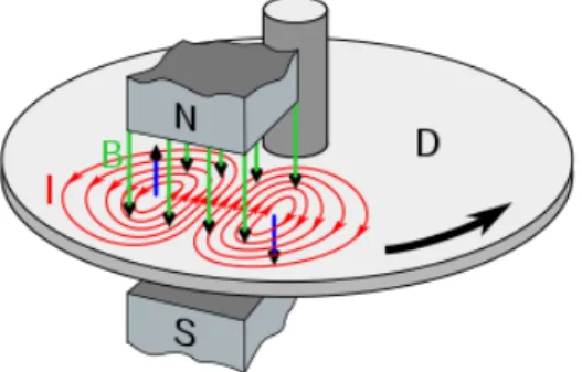
3.4.3 Eddy current brake
The Eddy current brake is very similar to an electric motor, again this will counter the MUT force and will be only in electric domain. The difference is that an Eddy current brake uses a dis instead of an axle, see figure 3.3. So there will be no friction, like a brushless DC motor. So the results will be more accurate then with an electric motor.
• RPM range (0-5000RPM)
At higher RPM the Eddy current brake will work good, but when the RPM will be lower, the magnetic field will be lower, therefore also the brake force.
• Torque range (0-5Nm)
The Eddy current brake can handle torque good, but not at low RPM be-cause it does not have force enough to stop the disk.
• Torque control
The brake can be controlled very well, if the magnetic field is higher the brake force will be higher. If the current is increased, also the brake force will increase.
• Cost of the system
The system has to be build, because there are not many eddy current brakes on the market. Therefore the system will not be expensive. Which should be bought are bearing, an axle and copper wire.
• Time to build the system
The build time will be very long, because all the coils have to be made. This is way too much for the time frame, for this project.
• Space of the system
Eddy current brakes are not very big, so it should fit in the old setup space. Only a power supply is needed to let it work.
Figure 3.3:Eddy current brake (Wikipedia, 2017)
3.4.4 Hydraulic inertia brake
The last option is a hydraulic inertia brake, This brake is often used in dynamo meters for gas fueled engines. Because they are very robust and can handle high torque and RPM (Grace Turner, 2016).
• RPM range (0-5000RPM)
The RPM range of a Hydraulic brake is good enough, it will be at least 5000RPM, because gas fueled engines turn at 7000RPM.
• Torque range (0-5Nm)
Also the torque will be sufficient, gas fueled engines, do have more torque than 5Nm.
• Torque control
To control the torque an electric motor is needed, which can regulate the flow of the hydraulic.
• Cost of the system The system is very expensive. The electric motor which regulates the flow must be very precise. Otherwise the torque-RPM curve will not be accurate enough.
• Time to build the system
In the schedule, there is not enough time to build this system. The sta-tor and rosta-tor should be build, this is precision work. If there is a leak the system will not work.
• Space of the system
The system is using more space than the old setup, because a Water reser-voir, electric pressure motor and the load are needed to let the system work.
CHAPTER 3. ANALYSIS 11
Figure 3.4:Hydraulic brake in a dynamomoter (Dealernews, 2014)
3.4.5 Combinations
Looking to the above solutions, nothing is the perfect solution. So maybe com-binations between systems will work. Like using 2 electric motors which can be changed. One with a gearbox the other without. So that the large range will be covered. Also a manual / electric gearbox can be put between the axle and the load motors. So that the system is fully electric. But this will cost more money and time. Another solution is to use one electric motor with a gearbox and one Eddy current brake. This would be a good solution. Only much time is needed to build an Eddy current brake.
3.4.6 Conclusion
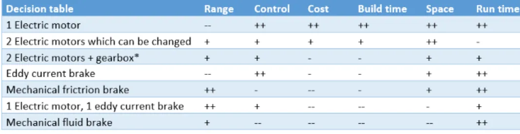
To get to the right active load, an decision table is made, this is shown in figure 3.5.
Figure 3.5:Decision table for the active load
Now it is visible that one electric motor has got the plus marks, but still this will not be the best option. Because the large range is the most important property, this cannot be neglected. So option two will be the best, using 2 electric motors, which can be changed. This solution is the cheapest and can be built in time, and still is sufficient to characterize different motors.
3.5 Modelling
3.5.1 Load arm and cell
load cell which RaM already had is a beam load cell. One side of the beam is connected to the frame and the other side to the load arm.
3.5.2 Solidworks model
Figure 3.6 is added, to see how the setup is modelled. The brackets will be bolted to the Frame, the frame will have slots instead of holes, and if a different load motor is put in the brackets it can be placed at the right place. On the left bracket an encoder will be placed, so the RPM of the MUT can be measured. This has to be done on the left bracket, because if the encoder is attached to the right bracket and the load motor has got a gearbox, the wrong RPM will be measured. The motor adapter is between the MUT and load motor, the load motor can be easily changed with a single bolt. The load arm which is the connection between the load motor and the load cell. The whole setup will be hold in with bearings, so that there is almost no losses by friction.
13
4 Design
After analyzing the setup, some new decisions needed to be made, find out ex-actly what is needed. So every wanted function will work. The subsystems are shown in figure 4.1. So first all the sensors will be chosen, after this a new model will be build, also 20-Sim models. After this the sensors can be calibrated and the setup can be build.
Figure 4.1:Block diagram of all the subsystems.
4.1 Sensors
In the setup two parameters are useful to characterize an electric motor, the torque and RPM as described in the background information. For the RPM an encoder will be used. And for the torque a load cell will be used, to measure the force over the arm.
4.1.1 Rotary encoder
To get a right RPM value, an encoder can be used. This device can convert angu-lar position of a shaft to a digital code. With only the anguangu-lar position the RPM cannot be calculated. The angular position has to be differentiated by time. See 4.1, t is in seconds and R rotations in that time.
RP M=60δR
δt (4.1)
at 5V and is trough hole. The encoder has got 200 CPR, this is accurate enough to measure the right RPM. To get the right RPM output a small 20-Sim model has to be made, because it is a quadrature optical encoder the counts will be 4 times as high, so 1 rotation has got 800 counts. The data sheet is in Avago Encoder (2012).
4.1.2 Load cell
A load cell will be used to measure the torque of the MUT. A load cell is a strain gauge, which measures the deformation of a beam. If force is applied on the beam the resistance changes in the strain gauge. The strain gauge could only measure force and not torque. So an arm is needed to transform the torque to a force. In the RaM storage there were some load cell. Looking at the data sheets of the load cells, concluded is that the Altheris FLL6D is the best fit. This load cell can measure till 2.5kg which is 24,52N. The nominal input voltage is 10V, this can be taken of the RaMstix with a voltage regulator.
Arm to load cell
As said before, an arm is needed to measure the torque of the MUT. In the anal-ysis the maximum torque is 5Nm. so if the whole range of the load cell is used. When equation 4.2 is used the length of the arm can be determined:
La=
T
F =
5, 0
24, 52=0, 20m (4.2) So the arm will be 0,2m. The arm will be made of stainless steel or aluminium. So it can handle the forces well, without deformation.
To compensate the difference a gain should be put in 20-sim.
T =F∗La=10N∗0, 20m=2, 0N m (4.3)
So 2,0Nm is 1,5V
G=T
V =
2, 0
1, 5=1, 33 (4.4) The gain will be 1,33.
Improvement during build
The mounting should be changed, because it was a fixed connection. Thereby the arm could not pass the force through at an angle of 90 degrees. So the hole at the end of the arm is changed for a slot. The load cell and load arm have a lose connection and can still move in horizontal direction.
4.2 Mounts of the load motor
To have an active load, the load motor should be exchangeable. To do this, some parts have to be able to adapt. Like the place of the mounting brackets, the load cell and the axle diameter.
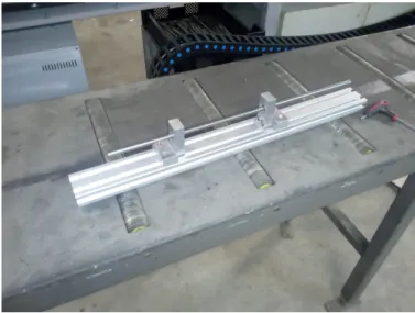
4.2.1 Mount brackets
CHAPTER 4. DESIGN 15 the bearings and there will be friction. This is not something which is wanted,
because energy lost will be lost.
The brackets have to be milled, at the right height, so is aligned with the axle of the MUT. The hole is milled at 75m height so the axle can go through. The axle will be hold in place by roller bearings with an inner diameter of 10mm, outer diameter 14mm and length of 10mm. After this process the brackets are tested, see picture 4.2. The axle can turn without much afford so the aligned is good.
Figure 4.2:Alignment of the brackets
4.2.2 Bearings
The setup will be hovering in 2 bearings which are in the brackets. Using bear-ings the friction of the axle will be less, and the results will improve the motor characterization. The inner diameter of the roller bearings will be 10mm, this is bigger than the rest of the axle which will be 6mm. Because a 6mm shaft + bear-ing will have more change at backlash than a 10mm shaft + bearbear-ing. Due to the accuracy of machines the bearings should be smaller, but the accuracy cannot be improved.
4.3 Axle
As said before the coupling shaft will have a diameter of 6mm. this is more than enough to transfer 5Nm. the MUT will be connected to the axle, but this will not have a very accurate aligned. Therefore 2 zero-backlash couplings are added, so the axle will not force itself into the bearings.
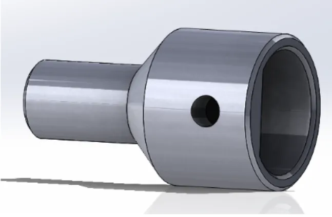
4.3.1 Motor adapter
Figure 4.3:Adapter to fit the load motor
The load motor adapters are milled, this was a time consuming process, because everything does have to be exactly as calculated. Otherwise backlash will appear, between the bearings and the adapter or between the adapter and the load mo-tor. After discussing with the technician in the Carré workspace, an accuracy of 0.1mm is allowed. Using Appendix A.4 the right sizes are milled.
Improvements during build
The axle has got some vibration to decrease this, different bearings or double bearings could be implemented. Because 3 the same bearings were ordered, so the second solution was chosen, in the bracket with the encode, two bearings are mounted. The backlash in the mount is much more less, but still some backlash is in the bearing.
To get less vibration in the axle the big bolts could be change to headless screws. There will be less weight at one side of the axle, so the vibration will be less. Now the axle is pretty long, thereby the load motor is of the build plate. If the axle is shortened it would fit at the plate.
To get less vibration the flex couplings could be changed for new ones, but this is not done. Because ordering those cost a few days and probably this will not make a big change, this time could be better spend.
4.4 20-Sim model
To test if the load does work, a 20-sim model has to be build, the torque and RPM should be inputs and there will also be 2 outputs, the voltage to the load motor and the voltage to the MUT. To characterize the MUT, it will be turned on, at maximal RPM. The load motor will start with an gain of 0 and with steps of 0.2 increase till 1. Therefore the whole domain will be tested of the MUT.
To let the Torque measurement work, the ADc input should be low pass filtered, around 1Hz otherwise there will be too much noise in the circuit. After this the signal should get an offset, because the load cell is horizontal mounted, and the gravity force of the load arm is forcing the load cell down already when the mo-tors are not working. At least the gain should be implemented, this is calculated earlier and is 1,33.
CHAPTER 4. DESIGN 17 there are 800 counts per rotation, so using again equation 4.5 the gain should be
decreased with:
RP M=δ(800∗R)
δ60 =13 1
3∗R (4.5)
After this only a low-pass filter is needed, to get the noise damped.
Figure 4.4:20-sim model
4.5 Prototype
Everything is mounted on the Boikon beam and the load is connected to the MUT. After a slow spin it was visible there was still some backlash in the adapter. After a re-alignment the backlash was less, so the first test run could be made. the setup is shown in figure 4.5.
At the first run, only the load cell was turned on. So the load cell could be tested. The results were not as expected, there was still a vibration in the load motor. See figure 4.6. Sadly the vertical axle is removed. The vibration was too big to do measurements therefore improvements have to be done, to get the system working better.
19
5 Results
After all the setup is renewed and is shown in figure 5.1.
Figure 5.1:Test setup with improvements
5.1 Calibration of the load cell
With the load cell there is an calibration certificate, this is shown in appendix A.2. The nominal input voltage is 10v and the sensitivity is 1,954mv/v so the maximal output will be 19,54mv. This is not enough to be measured by the ADC port of the RaMstix.
So a difference amplifier is needed. Because the load cell was already used on a RaMstix, the circuit was already designed. Only the parts and building did have to be done. In apendix A.3. Only R9 and R10 are replaced for 1k Ohm resistors and R7 and R8 for 250k Ohm. The amplifier has got a gain of 250 so the maximal voltage will be 4.885V. This is in the range of the ADc, because it can have an input voltage of maximal 5V.
Figure 5.2:Calibration of the Load cell
5.2 Complete test
Before the first demo, everything was finished in time. But just half an hour before the demo the load cell stopped working, as explained before. So there were no results. After changing the RaMstix it is working again.
CHAPTER 5. RESULTS 21
Figure 5.3:Results of test 23-6-2017
The torque - RPM curve is shown in figure 5.4. The curve does not say enough yet, because it only goes from 200 RPM till 900RPM. And is not as expected, be-cause at a low RPM the torque should be higher. This is not the case, probably due to the vibration in the axle.
6 Conclusion and Recommendations
The main target is to make an active load, which has got a large range for testing electric motors. Looking at the results, this is achieved, but still some improve-ments should be done, especially in 20-Sim. But the torque and RPM can be measured. By the test which is done the RPM can go up to 3300RPM and the Torque to 0.11Nm, this is normal for a electric motor without gearbox. But the theoretical values meet the requirements.
To summerize those values figure 6.1 is added.
Figure 6.1:The theoretical and practical results
Looking at the MoSCoW diagram, all the must haves are achieved. 2 Should haves are also met, a motor with gearbox and the motor temperature. The ef-ficiency test is also done, but not tested, because the input voltage and current are needed. And that was not part of this project.
6.0.1 Recommendations
23
A Appendix
A.1 Interviews
The interview results which are filled in by people of RaM.
A.2 Load cell calibration
APPENDIX A. APPENDIX 25
A.3 Difference amplifier
A.4 Adapter drawings
27
Bibliography
Avago Encoder (2012), HEDM-55xx/560x HEDS-55xx/56xx.
http://docs-europe.electrocomponents.com/webdocs/ 12cd/0900766b812cdcb5.pdf
Dealernews (2014), Dynamometers: everone talks horsepower, but how do you measure it?
http://dealernews.prod.as2.guidance.com/sites/www. dealernews.com/files/images/
4-graphic-Water-Brake-Cut-away.jpg
Grace Turner (2016), Hydraulic dynamometer.
https://me-mechanicalengineering.com/ dynamometer-introduction-types/
Industrial electronics (2017), DC motor testing.
http://www.industrial-electronics.com/images/ electric-motor_9-13.jpg
MIT (1999), Understanding D.C. Motor Characteristics.
http://lancet.mit.edu/motors/motors3.html
Morozovsky, N., R. Moroto and T. Bewley (2013), RAPID: An Inexpensive Open Source Dynamometer for Robotics Applications, IEEE, pp. 1855 – 1860, ISSN 1083-4435.
http:
//ieeexplore.ieee.org/document/6584831/?reload=true
Wikipedia (2017), Figure of an Eddy current brake.
https://upload.wikimedia.org/wikipedia/commons/thumb/ 5/50/Eddy_current_brake_diagram.svg/310px-Eddy_