A Thesis Submitted for the Degree of PhD at the University of Warwick
Permanent WRAP URL:
http://wrap.warwick.ac.uk/
130552
Copyright and reuse:
This thesis is made available online and is protected by original copyright.
Please scroll down to view the document itself.
Please refer to the repository record for this item for information to help you to cite it.
Our policy information is available from the repository home page.
THE FABRICATION AND ANALYSIS OF
HARD, Si3N4-BASED, DISPERSED PHASE COMPOSITES
Olwen J. Pullum
Thesis subm itted for the degree of Doctor of Philosophy (PhD)
University of W arwick
D epartm ent of Physics
ABSTRACT
This thesis describes experiments which were carried out to fabricate new silicon nitride-based ceramic composites and to analyse their microstructural and physical characteristics. Possible applications considered were those involving high hardness or wear-resistant properties.
Two composite systems were investigated which had either silicon carbide platelets or cubic boron nitride particles, dispersed in a silicon nitride matrix (or binder) phase. The composites were fabricated using unconventional techniques, involving the hot-pressing of hybrid, laminated composites and ultra-high pressure sintering (at pressures exceeding 4 GPa). Each of these techniques was considered to offer a means of improving the fracture toughness of the ceramics, in addition to the high hardness.
Hybrid, laminated SiC-Si3N4 composites were succesfully fabricated by hot- pressing composites consisting of structurally arranged tape cast laminae with different
proportions of SiC platelets. These composites showed promising indications of
enhanced fracture toughness through delamination along laminar interfaces in addition to microstructural toughening mechanisms within the laminae.
Fabrication by ultra-high pressure sintering was found to be detrimental to the mechanical properties of the SiC-Si3N4 composites and it is suggested that the microstructural toughening effects due to the SiC platelets were rendered ineffective by residual stresses believed to arise from the ultra-high pressure process. Particularly low fracture toughnesses of 2.0 to 3.4 MPam1/2 were determined for these composites and the Vickers hardness values were close to 20 GPa.
Additional studies were made on these composites to examine a polytypic phase transformation (to 3C SiC) that was induced in the platelets by the extreme
fabrication conditions. This was attributed to the co-operative motion of partial
dislocations on the basal planes.
TABLE OF CONTENTS
Page
Abstract (0
Table o f Contents ('0
List o f Figures (v0
List o f Tables M
Acknowledgements (*0
Declaration W
List o f Abbreviations (xiii)
Chapter One
INTRODUCTION
1.0 DEVELOPMENTS IN ADVANCED CERAMICS 1
1.1 CERAMICS FOR HIGH-HARDNESS APPLICATIONS 3
1.2 CERAMIC FRACTURE BEHAVIOUR AND 'FRACTURE TOUGHNESS' 6
1.2.1 Ceramic Fracture Behaviour 6
1.2.2 Ceramic Toughening 7
1.3 RESEARCH OBJECTIVES 8
Chapter Two
FABRICA TION, PRO PERTIES AND M ICRO STRU CTU RE OF CERAM ICS BASED ON
SILICON N ITRID E, SILICO N CARBIDE AND CUBIC BORON NITRIDE
2.0 INTRODUCTION 10
2.1 SILICON NITRIDE CERAMICS 10
2.1.1 Silicon Nitride Crystal Structures 10
2.1.2 Fabrication o f Polycrystalline Silicon Nitride 11
(i) Liquid Phase Sintering 12
(ii) Pressure-Assisted Sintering 13
2.1.3 Silicon Nitride Sintering Additive Systems 14
(i) SiAlON Ceramics 14
(ii) Non-sialon-forming additives 14
2.2 DISPERSED-PHASE CERAMIC COMPOSITES 16
2.2.1 Dispersed-Phase Composite Toughening Mechanisms 17
(i) Crack Interaction with Dispersed Inclusions 18
(ii) Crack Deflection 18
(iii) Crack Bridging 19
(iv) Microcrack Toughening 21
2.2.2 Silicon Carbide Platelet Reinforcement 22
2.2.3 Fabrication o f Dispersed-Phase Composites 23
(i) Green State Preparation 23
(ii) Sintering and Densification 24
2.2.4 Fabrication o f Hybrid Composites 25
2.3 CERAMIC FABRICATION AT ULTRA-HIGH PRESSURES 26
2.3.1 Introduction to Ultra-High Pressure Fabrication 26
(i) Properties o f Cubic BN 28
(ii) The Boron Nitride Phase Diagram 29
(Hi) Catalytic Synthesis o f Cubic BN 30
2.3.3 Fabrication o f Cubic Boron Nitride Composites 31
2.3.4 Cubic boron nitride / Silicon nitride Composites 32
2.3.5 Consolidation Mechanisms o f Poly crystalline Cubic Boron Nitride 34
2.3.6 Application o f Ultra-High Pressures to Ceramic Sintering 35
2.4 THE STRUCTURAL RELATIONSHIP BETWEEN POLYTYPES OF
SILICON CARBIDE 36
2.4.1 Silicon Carbide Crystal Structures 36
2.4.2 Relative Polytypic Phase Stabilities 37
2.4.3 Plastic Deformation in Silicon Carbide 38
2.5 THE SPECIFIC RESEARCH OBJECTIVES 39
Chapter Three
EXPERIM ENTAL M ATERIALS AND TECHNIQUES
3.1 POWDER PROCESSING 40
3.1.1 Preparation o f the Silicon nitride-based Ceramic Matrix Phase 41
3.1.2 Preparation o f Green State Composites and Slip Casting 42
3.1.3 Tape Casting 43
3.1.4 Thermogravimetric Analysis 45
3.2 HOT PRESSING 45
3.3 ULTRA-HIGH PRESSURE FABRICATION 46
3.3.1 Ceramic Fabrication using the Belt Apparatus 47
3.3.2 Ceramic Fabrication in the Tetrahedral Anvil System 48
3.4 X-RAY DIFFRACTION 49
3.5 ELECTRON MICROSCOPY 50
3.5.1 Scanning Electron Microscopy (SEM) 50
(i) SEM Specimen Preparation 50
(ii) SEM Operational Procedures 50
3.5.2 Transmission Electron Microscopy 52
(i) TEM Specimen Preparation 52
(ii) TEM Operational Procedures 52
3.6 MAGIC ANGLE SPINNING NUCLEAR MAGNETIC RESONANCE 54
3.7 DENSITY MEASUREMENT 55
3.8 INDENTATION EXPERIMENTS 55
3.9 CERAMIC STRENGTH MEASUREMENT 58
3.10 SINGLE-EDGE NOTCHED BEAM FRACTURE TOUGHNESS 59
3.11 LINEAR THERMAL EXPANSION 60
Chapter F our
FABRICATION AND M ICROSTRUCTURE OF SILIC O N NITRIDE CERAM ICS TOUGHENED W ITH SILICON CARBIDE
4.0 INTRODUCTION ’ 62
4.1 THE FABRICATION OF HYBRID, LAMINATED CERAMICS 63
4.1.2 Experimental Procedure fo r Laminate Fabrication 64
4.2 TAPE CASTING EXPERIMENTS 65
4.2.1 The Influence o f Organic Components on Ceramic Powder Suspensions 67
4.2.2 The Effect o f Ceramic Composition on Tape Fabrication 68
4.2.3 Laminate Construction 70
4.3 REMOVAL OF ORGANIC TAPE COMPONENTS 70
4.4 HOT PRESSING 71
4.5 THE MICROSTRUCTURE OF HYBRID, LAMINATED COMPOSITES 73
4.5.1 Scanning Electron Microscope Observations 73
4.5.2 Transmission Electron Microscope Observations 74
4.6 SILICON CARBIDE / SILICON NITRIDE CERAMIC FABRICATION
AT ULTRA-HIGH PRESSURES 75
4.6.1 Experimental Procedure fo r Ultra-High Pressure Ceramic Fabrication 75
4.7 PHASE IDENTIFICATION BY X-RAY DIFFRACTION 76
4.8 STRUCTURAL ANALYSIS USING SILICON-29 MAGIC ANGLE
SPINNING NUCLEAR MAGNETIC RESONANCE 77
4.8.1 Determination o f Post-Processing Structural Changes in Silicon Carbide Platelets 77
4.8.2 SiC Polytype Identification Using29Si Chemical Shift Data 80
4.8.3 The Structural Stability o f Silicon Carbide Platelets During Ceramic Fabrication 81
4.9 TRANSMISSION ELECTRON MICROSCOPE INVESTIGATION OF THE 83
PHASE TRANSFORMATION IN SILICON CARBIDE PLATELETS
4.10 DISCUSSION OF THE HIGH-PRESSURE PHASE TRANSFORMATION IN 85
SILICON CARBIDE PLATELETS
4.10.1 Mechanism fo r the Hexagonal to Cubic Silicon Carbide Phase Transformation 85
4.11 SUMMARY AND CONCLUSIONS 87
Chapter Five
ULTRA-HIGH PRESSURE FABRICATION AND M ICROSTRU CTU RE O F CUBIC BORON NITRIDE / SILICON N ITRID E COM POSITES
5.0 INTRODUCTION 89
5.1 FABRICATION OF THE cBN-Si3N4 CERAMIC COMPOSITES 90
5.1.1 Fabrication Objectives and Composition Selection 90
5.1.2 Experimental Procedures fo r cBN-SijNj Composite Fabrication 90
5.2 GREEN STATE COMPOSITE PREPARATION 92
5.3 ULTRA-HIGH PRESSURE SINTERING 93
5.3.1 The Sintering Cycle 94
5.3.2 Capsule Modification in the High-Pressure'Belt'Apparatus 94
5.3.3 Sources o f Difficulty in Repeating the Fabrication Experiments 95
5.4 PHYSICAL APPEARANCE OF THE cBN-Si3N4 COMPOSITES 96
5.5 DENSITY MEASUREMENTS 96
5.6 PHASE ANALYSIS USING X-RAY DIFFRACTION 98
5.6.1 XRD Results fo r Ceramics Fabricated at 4.0 - 5.0 GPa 98
5.6.2 XRD Results fo r Ceramics Fabricated at Pressures Above 8 GPa 99
5.7.1 Tape-cast, Laminated Ceramic 101
5.8 TRANSMISSION ELECTRON MICROSCOPE OBSERVATIONS 102
5.9 SUMMARY AND CONCLUSIONS 103
Chapter Six
PHYSICAL PRO PERTIES O F SILICON CARBIDE / SILICON N ITRID E AND CUBIC BORON N IT R ID E / SILICON NITRIDE C O M PO SITES
6.0 INTRODUCTION 105
6.1 INDENTATION HARDNESS 106
6.1.1 Vickers Indentation Hardness 106
6.1.2 Knoop Indentation Hardness 108
6.2 RESULTS OF CERAMIC STRENGTH MEASUREMENT 110
6.3 CERAMIC FRACTURE TOUGHNESS 112
6.3.1 SENB Fracture Toughness o f cBN-SijNj Composites 113
6.3.2 Indentation Fracture Toughness 114
6.3.3 Crack Propagation 117
6.4 DISCUSSION OF COMPOSITE TOUGHENING MECHANISMS 119
6.5 LINEAR THERMAL EXPANSION EXPERIMENTS 121
6.5.1 Thermal Expansion o f SiC-SijNj Laminates 121
6.5.2 Thermal Expansion o f cBN-SijNj Composites 122
6.6 SUMMARY AND CONCLUSIONS 124
Chapter Seven
CONCLUSIONS AND SUGGESTIONS FO R FUTURE W ORK
7.1 THE SILICON NITRIDE MATRIX PHASE 126
7.2 SiC-Si3N4 LAMINATED COMPOSITES 126
7.3 SiC-Si3N4 COMPOSITES FABRICATED AT EXTREME PRESSURES 128
7.4 cBN-Si3N4 CERAMIC COMPOSITES 130
7.5 SUGGESTIONS FOR FUTURE WORK 132
APPENDIX A 133
COMPOSITION OF THE CERAMIC MATRIX PHASE
APPENDIX B 134
THEORETICAL DENSITIES CALCULATED FROM THE LAW OF MIXTURES
APPENDIX C 136
CHEMICAL SHIFT DATA FOR THE SiC POLYTYPES
APPENDIX D 137
CALCULATION OF RESIDUAL THERMAL STRESS IN HYBRID COMPOSITES
LIST OF FIGURES
Figure Page
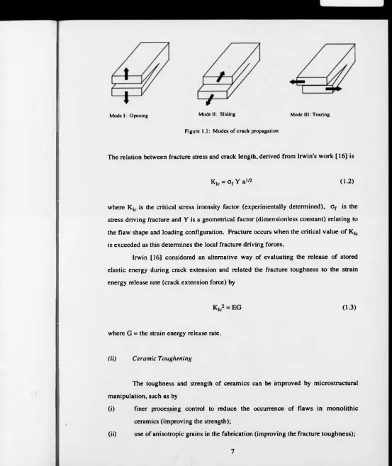
1.1 Modes o f Crack Propagation 1
2. 1 Crystal structure o f 3-Si3N4 11
2 .2 Densification o f S i3N4 by liquid phase sintering 12
2. 3 Phase relationships in the Si3N4- S i0 2-Y20 3-YN system, after [39] 15 2 . 4 Crack deflection by a dispersed phase (hexagonal platelets) 18 2. 5 Predicted toughening increases from crack deflection around discs or rod-shaped inclusions as a 19
function o f volume fraction and aspect ratio, R (adapted from [51].
2 . 6 Crack bridging processes giving rise to toughening 20
2. 7 Crystal structures o f boron nitride: (a) cubic BN, (b) hexagonal BN, (c) wurtzitic BN 27
2 .8 Boron Nitride Phase Diagram 30
2. 9 Crystal structures o f the cubic (3C) polytype and the 4H and 6H hexagonal polytypes o f SiC, 37 viewed normal to the c-axis.
3. 1 Enlarged comer o f the Si-Y-O-N phase diagram, taken from figure 2.3. 41 3. 2 Apparatus used for the tape casting o f ball-milled, ceramic powder suspensions. 43 3. 3 Construction o f the graphite die in which ceramic powders were sintered. 45 3. 4 Cross-section o f the ultra-high pressure 'belt' apparatus, after [145]. 47 3. 5 Cross-section o f a typical sintering capsule with salt as the 'pressure-transmitting' medium. 48 3. 6 (a) single anvil from the tetrahedral system (b) cross-section o f the pyrophyllite tetrahedron 49
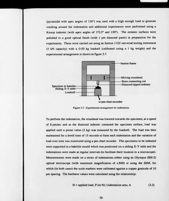
3 .7 Experimental arrangement for indentation 56
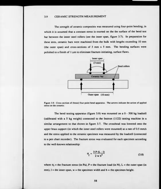
3. 8 Surface impression made by a Vickers diamond indenter 57 3. 9 Cross-section o f (brass) four-point bend apparatus. The arrows indicate the action o f applied 58
stress on the ceramic.
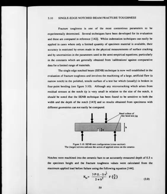
3.10 SENB test configuration (cross-section). The (larger) arrows indicate the action of applied stress 59 on the ceramic.
3.11 Cross-section o f the quartz dilatometer used for thermal expansion experiments. 60
4. 1 Macrostructural designs for laminated ceramic composites 64 4. 2 Flow diagram summarising the procedure for ceramic tape fabrication 66 4. 3 X-ray map showing the dispersion o f the Y20 3 sintering additive in the Si,N 4-based ceramic after 68
matrix powder after ball milling.
4. 4 Secondary SEM image o f the 'as received' SiC platelets. The SiC basal plane lies in the plane of after 68 the platelets.
4. 5 Secondary SEM image o f the upper tape-cast surface of a (green state) SiC -Si3N4 lamina. after 69 4. 6 Secondary SEM image of the lower tape-cast surface of a SiC-Si3N 4 lamina, after its removal after 69
from the carrier sheet.
4. 7 Constant heating rate thcrmogravimetric analysis experiments for a single, monolithic tape. after 70 4. 8 Heating cycle for removal of the organic component in fabricated tapes. after 70 4. 9 Hot pressing cycle used in the laminate fabrication 71 4.10 XRD spectra taken from a laminate constructed with alternating layers o f monolithic Si3N4 ( a after 72
and 3 peaks are labelled) and SiC (60 wt%)-Si3N4, that was hot-pressed at 50 MPa and 1710° for 180 minutes. Spectrum (a) was acquired from a surface orientated parallel to the hot-pressing direction whereas spectrum (b) was acquired from a monolithic surface orientated perpendicular to the hot-pressing direction. The additional, unlabcllcd peaks arise from the SiC platelets in the ceramic.
4.12 4.13 4.14 4.15 4.16 4.17 4.18 4.19 4.20 4.21 4.22 4.23 4.24 4.25 4.26 4.27 4.28 4.29 4.30 laminae.
Back-scattered SEM image of the polished cross-section o f a SiC (60 wt%)-Si3N4 layer from the composite shown in figure 4.11.
Back-scattered SEM image o f the cross-section o f a hybrid composite fabricated at 20 MPa. showing an increasing concentration o f SiC platelets from the bottom to the top of the figure. Back-scattered SEM image showing a cross-sectional view o f the laminae with the lowest SiC volume fraction dispersed in the matrix phase.
Bright-field TEM image showing a region o f the Si3N4-bascd matrix phase in a hot-pressed (at 30 MPa) laminate, surrounded by the relatively large SiC platelets.
TEM image of Si3N4 crystals and the glassy, intergranular yttrium silicate phase in a hot-pressed laminate.
X-ray diffraction from the surface o f a monolithic Si3N4 ceramic fabricated at ultra-high pressures.
X-ray diffraction from (a) SiC platelets that were subjected to the ultra-high pressure conditions used in composite fabrication and (b) the 'as received' platelets.
X-ray diffraction from different orientations o f a SiC-Si3N4 composite fabricated at ultra-high pressure: (a) from a surface cut perpendicular to the direction of anvil motion; (b) from a surface cut parallel to the direction o f anvil motion; (c) the powder diffraction spectrum.
w Si chemical shifts (from the tetramethylsilane reference peak) for three SiC-Si3N4 composites fabricated at ultra-high pressures, using a three minute relaxation delay time.
29Si chemical shifts (from the tctramethylsilane reference peak) for (a) a SiC-Si3N4 composite (with >80 wt% SiC) fabricated at ultra-high pressures and (b) the 'as received' SiC platelets. Both spectra were acquired using a 30 minute relaxation delay time.
Comparison o f the 29Si chemical shifts (from the tetramethylsilane reference peak) for SiC platelets subjected to different processing conditions: (a) from a UHP-sintered ceramic (reproduced from figure 4.20 a); (b) from a SiC-Si3N4 composite fabricated by hot-pressing at 20 MPa; (c) from the 'as received' SiC platelets.
29Si chemical shifts (from the tctramcthylsilane reference peak) for (a) a SiC -Si,N 4 composite that had been fabricated by HIPing at 160 MPa and 1725°C and (b) the unprocessed SiC platelets used for the composite fabrication.
29Si chemical shifts (from the tctramcthylsilane reference peak) for (a) SiC platelets subjected to ultra-high pressures at ambient temperature and (b) the 'as received' SiC platelets.
Back-scattcred SEM image taken from a SiC-Si3N4 composite fabricated at UHP, showing (relatively large) SiC platelets, viewed perpendicular to the platelet plane, dispersed in a P-Si3N4-bascd matrix phase.
Bright field TEM image demonstrating extensive plastic deformation o f the SiC platelets, including stacking faults and 'kink' boundaries within individual platelets.
Bright field TEM image o f severe stacking fault deformation on multiple platelet planes. Inset: superposition of two [lOTO] diffraction patterns, with streaking arising from the fine stacking fault deformation.
Selected area electron diffraction patterns used to identify the presence o f different SiC polytypes in SiC-Si3N4 composites. Patterns (a) and (b) were obtained from SiC platelets in a hot-pressed composite whereas patterns (c), (d), (c) and (0 were obtained from platelets in UHP-fabneated composites. The identity o f the patterns is as follows: (a) [10T0] zone axis, 4H polytype; (b) [lOTO] zone axis, 15R polytype; (c) [lOTO] zone axis, 4H polytype; (d) [10T0] zone axis, I5R polytype; (e) [ 10T0] zone axis, 6H polytype; (0 [110] zone axis, 3C polytype. Bright field TEM image o f a 6H platelet, viewed perpendicular to the basal planes, revealing the structural periodicity along the c-axis. Inset: overlapping diffraction patterns from regions o f the 6H and 3C SiC phases.
Bright field TEM image of a SiC platelet, viewed perpendicular to the basal planes. The distance between the most closely spaced lines corresponds with the 6H c-axis lattice parameter.
4.31 4.32
3. 1
5.2
5. 3 5.4
5 .5
5 . 6
5 .7 5 .8 5 .9 5.10 5.11 5.12 5.13 5.14 5.15 5.16 5.17 5.18
Bright field TEM image o f inclined dislocations, viewed along the [0001] zone axis.
The sequential change in stacking sequence from that for 6H SiC (left) to that o f the cubic, 3C phase (right) via repeated dislocation glide on consecutive basal planes. The vertical direction is parallel to the c-axis.
Flowchart illustrating the procedure followed for the high pressure fabrication and evaluation of cBN-Si3N4 ceramics. The shaded boxes in the 'ultra-high pressure processing' section represent parameters that were varied in order to change the conditions directly experienced by specimens during the fabrication process (heavily outlined boxes). The ways in which the fabricated composites were evaluated are summarised in the 'evaluation' section and the results are presented later in this chapter and in chapter six.
Ultra-high pressure sintering cycle for cBN-Si3N4 ceramics fabricated at 8 GPa. The experiments carried out at other pressures and heating powers followed the same pattern as is shown here.
Cross-section o f the high temperature sintering capsule.
XRD spectrum acquired from a cBN (80 wt%)-Si3N4 composite fabricated at 4.5 GPa (in the belt' apparatus).
XRD spectra acquired from specimens fabricated at the following relatively controlled conditions in the tetrahedral anvil apparatus: (a) 4.5 GPa, 1750°C; (b) 5.0 GPa, 1700°C; (c) 5.0 GPa, 1650°C.
XRD spectra for cBN -Si3N4 composites with different cBN concentration, fabricated at 8 GPa: (a) 40 wt% cBN; (b) 60 wt% cBN; (c) 80 wt% cBN.
XRD spectrum for an hBN-Si3N4 composite that was sintered at 8 GPa.
Back-scattered SEM image o f the polished surface o f a cBN (60 wt%)-Si3N4 ceramic showing the distribution o f cBN grains (black) in the Si3N4 (grey)-bascd matrix. The white 'specks' represent regions with relatively high quantities o f sintering additive (yttrium containing) residue.
Back-scattered SEM image showing a region with considerable fragmentation o f the cBN grains where they have been forced into direct contact. Inset: EDAX spectrum taken from a cBN grain.
Back-scattered SEM image taken from a polished surface o f a cBN (60 wt%)-Si3N4 composite and from which the sintering cncapsulant (tantalum) had not been removed.
Three images formed by X-ray mapping which separately show the distribution o f silicon, iron and tantalum across the ceramic-capsule interface. The secondary electron SEM image o f this region is given in the bottom right hand comer.
XRD spectrum identifying the phases present in (a) the ceramic surface with a composition o f 80 wl% cBN; (b) the opposing ceramic face, predominantly o f the Si3N4 phase.
Polished cross-section o f the hybrid cBN -Si3N4 composite. The boundary between laminae of different compositions is clearly defined.
Cross-section o f the hybrid cBN-Si3N4 composite showing the macrostructural disorder after the disruption o f sequentially stacked laminae during the UHP sintering process.
Bright field TEM image illustrating the relative sizes o f the (large) cBN grains and the much finer S i3N4 grains. Extensive plastic deformation is responsible for the contrast variations seen on the cBN grains. Additionally, some mechanical twinning is visible on the largest cBN grain. Bright field TEM image, showing a section through the Si3N4-bascd matrix phase (taken from a monolithic ceramic fabricated at 4.5 GPa and 1750°C, in the tetrahedral anvil apparatus). Inset: EDAX analysis o f the glassy phase between the Si3N4 grains. The presence o f the Si and N peaks is partly due to some overlap o f the probe electron beam with the Si3N4 grains.
Bright field TEM image, showing a region o f the Si3N4 matrix phase between the much larger, plastically deformed cBN grains.
EELS spectrum, taken from a cBN grain, for which the fine structure have been identified with
after 84 86 91 94 95 after 98 after 98 after 99
after 100 after 100
after 100
after 101
after 101
after 101
after 101
after 101
after 102
after 102
after 102
5.19
5.20
6. 1
6.2 6 .3 6 .4 6 .5 6.6 6.8 6 .9
6. 10
6.11
6.12
6.13
6.14 6.15
reference to [164].
Bright field TEM image, showing a region o f the glassy phase found at S i3N4 grain boundaries and the EDAX analysis giving the elemental composition o f the glassy phase.
Mechanical twins, viewed along the [110] zone axis: (a) Dark field image o f twins on the [ i l l ) cBN planes; (b) Dark field image showing twins on the { lTT) planes; (c) Bright field image with (inset) the associated [110] cBN diffraction pattern.
Bar chart illustrating the mean values (by the height o f the front face) o f Vickers indentation hardness, obtained using a 2 kg load. The error bars represent the standard error in the mean. The specimen marked T was hot-pressed whereas specimen '2' was UHP-sintered. Specimen 'X' was fabricated using a larger cBN grain size (average particle size, 9 pm).
Back-scattered SEM images o f Vickers indentations (made using a 2 kg load) on polished surfaces of a (a) 60 wt% cBN composite; (b) 80 wt% cBN composite; (c) Si , N4 monolithic ceramic. All the images are shown at the same magnification.
Bar chart illustrating the mean values o f the Knoop hardness, obtained using a 2 kg load, for a selection of ceramic specimens. The error bars represent the standard error in the mean. Bar chart comparing the mean strengths o f the different composites, as determined from four-point bend testing. Two sets o f data were obtained from different batches (T and '2') o f the 80 wt% cBN composition. The error bars represent the standard error in the mean. (The results obtained from the SiC-Si3N4 laminate were obtined using the monolithic face as the tensile surface.)
Weibull plots o f the strength measurements made on different ceramic composites (labelled) to illustrate the proportion of specimens that 'fail' below a given strength value. 'F%' (on the y-axes) is the cumulative percentage o f the sample population that has 'failed', 'm' is the Weibull modulus and the 'log' is the natural logarithm. Lines o f the 'least squares fit' have been drawn through the points.
Bar chart comparing the fracture toughnesses o f the cB N -Si3N4 composites, as determined using the SENB technique. The error bars represent the standard error in the mean.
The mean crack lengths emanating from a 2 kg Vickers indentation, plotted for the SiC-Si3N4 composites fabricated at UHP (open circles on the graph) and the cBN (40 wt%)-Si3N4 composite (labelled). The error bars represent the standard error in the mean.
Back-scattered SEM image o f crack propagation in a 20 wt% SiC composite fabricated at 4 - 5 OPa.
Back-scattered SEM image o f crack deflection along the SiC^-matrix interface in a 20 wt% SiC composite fabricated at 4 - 5 GPa.
Back-scattered SEM image o f a Vickers indentation (formed using a 2 kg indenter load) in the >80 wt% SiC composite.
Secondary SEM image o f a rough fracture surface in a SiC-Si3N4 laminate, viewed perpendicular to the plane o f fracture.
Back-scattered SEM image o f a Vickers indentation (formed using a 2 kg indenter load) in a 40 wt% cBN composite.
Back-scattered SEM image o f a crack (centre) propagating in a 40 wt% cBN composite. Thermal expansion behaviour of a 40 wt% cBN composite (with the larger grain size) during the initial (coloured circles on graph) and the second (open circles) experiments performed on this specimen.
after 103
after 103
106
after 107
108
110
after 111
113
115
after 117
after 117
after 118
after 118
after 118
ACKNOWLEDGEMENTS
I would like to thank Prof. M. H. Lewis for his encouragement, guidance and supervision of this research project. I would also like to thank Dr. R. J. Caveney and the De Beers Industrial Diamond Laboratory for their generous funding of the research and for my visit to their laboratories. In particular, I would like to express gratitude to Dr. R. A. Chapman and Lucas for their assistance with the experiments at these laboratories and also, for their general encouragement.
Some supplementary high pressure experiments were carried out at the SERC High Pressure Laboratory (based in the former STC laboratories, Essex) for which I would like to thank Dr. J. Lees for permission to use the facility and Mr. G. Bolton for his proficient technical assistance.
The majority of the research was carried out at Warwick where many people have offered me much valued support and encouragement. I would especially like to thank Steve York and Gerald Smith for their initial tuition and assistance in electron microscopy, Dan Lee for helping me to cut, grind and polish numerous ceramic specimens, Dave Hammond for his assistance with the hot press, Simon Kohn and Andy Howes for their assistance in acquiring the MAS-NMR spectra and for useful discussions about the technique and John Lumby for some very helpful conversations concerning the mechanical testing of materials.
I am grateful to my office colleagues and to other friends and staff in the
department for their part in creating a pleasant working environment. The
encouragement of friends outside the department has also been very welcome. In particular, I am appreciative of encouragement from Alan Taylor, Stuart Sutherland and Nick Davies.
DECLARATION
This thesis contains an account of my own independent research work, carried
out between November 1988 and January 1993. Any contributions from outside
research have been specifically acknowledged in the text. No part of this work has been submitted to this or any other institution in respect of a degree or other qualification. However, some aspects of the research have been presented as follows:
(i) O. J. Pullum and M. H. Lewis, Microstructure o f Cubic Boron Nitride Ceram ics, Proc.
Diamond Conference, Reading, July 1990
(ii) O. J. Pullum and M. H. Lewis, Tape-Cast lam inates o f D ispersoid (cBN. SiC) - Containing
Ceramics, Proc. Diamond Conference, Oxford, July 1991
(ii) O. J. Pullum and M. H. Lewis, A High Pressure Phase Transition in Silicon Carbide, Proc.
Diamond Conference, Cambridge 1992.
The results of some preliminary investigations conducted at the beginning of the research (bound at the back of the thesis) have been published as
O. J. Pullum and M. H. Lewis, Mater. Lett. 9 [2,3] (1990), Microstructural A nalysis o f a
L IS T OF ABBREVIATIONS
o phase identifier for a-S ijN 4, on XRD spectra
0 phase identifier for 0-Si3N4, on XRD spectra
EDAX Energy Dispersive Analysis of X-rays
EELS Electron Energy Loss Spectroscopy
HIP Hot Isostatic Pressure
JCPDS Joint Committee for Powder Diffraction Standards
MAS-NMR Magic Angle Spinning Nuclear Magnetic Resonance
ppm parts per million
r.f. radio frequency
SEM Scanning Electron Microscopy
SiCp SERR
Silicon carbide Platelet Strain energy release rate
TEM Transmission Electron Microscopy
TGA Thermogravimetric Analysis
UHP Ultra-High Pressure
wt% percentage by weight
Chapter One
INTRODUCTION
1.0 DEVELOPMENTS IN ADVANCED CERAMICS
'Advanced' ceramic materials are normally polycrystalline masses of inorganic, non-metallic compounds with unique combinations of physical and chemical properties that are the result of strong, mixed ionic-covalent bonding. Typical ceramic properties include high melting (or dissociation) points, low densities and good chemical stability, all desirable attributes for engineering purposes. Advanced ceramics are to be found in electronic devices (capacitors, packaging, semiconductors, superconductors), optical
devices (nonlinear and laser optics), thermal and magnetic devices. As structural
components, ceramics are able to withstand extreme environmental conditions and ceramic coatings are often used to protect other materials from corrosion. Structural applications range from dental implants and bone replacements (for which alumina and porcelain have become recognised as good 'bioinert' materials) to wear-resistant applications and components for gas turbine engines, where the more covalent ceramics can survive at elevated temperatures (above 1000°C) and, being lightweight, can operate at faster speeds than are possible using metallic components. Therefore, the use of ceramic components can lead to dramatic increases in engine efficiency.
Ceramic materials are fabricated by sintering together a porous mass of very pure, fine powders. This process requires temperatures of 1000-2000°C to promote material diffusion as the mass densifies with elimination of the pores. For the more strongly covalent ceramics with low self-diffusion rates, successful powder consolidation often requires the simultaneous application of external pressures during sintering, which proceeds by a 'liquid phase sintering' process described in chapter two. These fabrication pressures vary from a few hundred atmospheres for most conventional processes, to tens of thousands of atmospheres in the highly specialised processes associated with ultrahard, diamond-like materials.
Processing methods that prove most beneficial for particular ceramic properties are usually evaluated by detailed investigations of the post-fabrication microstructure in
conjunction with studies made on the physical properties. The microstructural
observations can then be used to gain an understanding of mechanical behaviour and also to guide modifications that may be made to the fabrication techniques. Whilst the sintering temperatures and external fabrication pressures determine the final phase compositions and residual porosity levels, the powder treatment prior to sintering also has a significant influence on the microstructure. Despite there being fairly well established techniques for powder processing, these cannot be applied universally to all ceramic powders without some experimentation. As most powder preparation is carried out in a liquid medium, processing techniques must often be adapted to accommodate variations in particle size, surface chemistry and interaction with the liquid medium.
The research described in the ensuing chapters concerns hard, structural ceramics relevant to applications for wear resistance or high hardness and cutting tool materials. Since engineering materials are continually being developed to meet the needs of specific applications (for example, new aerospace alloys, ceramics for gas turbines) there is an increasing demand for cutting tools specially suited for rapid mass production, having a long tool life and high impact resistance whilst causing little
machining damage. In recent decades progress has been m ade towards enabling
microstructurally engineered tolerance of impact damage, rendering them suitable for an ever widening range of applications.
The remaining sections of this chapter introduce those ceramics used for cutting tool tips, the concept of ceramic 'fracture toughness' and finally, the objectives of this research project. Chapter two presents a detailed review of the fabrication and properties of the types of materials involved in this research and of the microstructural toughening behaviour of ceramic matrix composites. The fabrication and analytical techniques that have been used in this work are described in chapter three and the remaining chapters contain the findings of this research.
1.1 CERAMICS FOR HIGH-HARDNESS APPLICATIONS
The structural ceramics are attractive materials for use in cutting tools due to their high hardness, good physical and chemical wear resistance and thermal stability. Ceramics rival metal tools, particularly the hard steels used in the cutting of high melting point materials (iron, steel) where temperatures generated at the cutting edge may be as high as 900°C [1] and also compete with the 'cermets' (metal-ceramic alloys)
such as tungsten carbide/cobalt alloys. At such temperatures ceramics are less
susceptible to the problems suffered by metals which restrict the operational cutting speeds. As ceramic tools require lower cutting forces and have greater compressive strengths than metals, ceramic tool tips are less likely to deteriorate at high machining speeds. In addition, metal tools may undergo temperature-induced structural changes that can affect their hardness and wear resistance, so limiting their efficiency.
The oxide ceramics (alumina, zirconia) have a very high oxidation resistance and are used mostly for refractory purposes. Alumina is also used as a component phase in cutting tool tips, but has poor thermal shock resistance compared with the strongly covalent, non-oxide ceramics. Silicon nitride, silicon carbide and the 'sialons' (derived from Si3N4) have high hardness, low thermal expansion and good high temperature strength retention. All are now established in cutting and wear resistant
operations. Some physical properties of selected structural ceramics are given in
[image:18.598.0.573.24.676.2]Table 1: Physical properties of selected wear-resistant ceramics
Ceramic + Hardness ToughnessFracture ModulusYoung’s Linear ThermalExpansion Source silicon nitride 14.1 GPa
18.5 GPa
4.9 MPam1/2
4.0 MPam1/2 300 GPa
3.0 - 3.2 x lö V '1 [21 [3] [4]
silicon carbide 19.3 GPa 24.0 GPa
4.0 MPaml/2
4.0 MPam " 436 GPa
4.4 - 4.8 x IO"*k ‘ [2] [3] [41 . „ . ™ Lucas Syalon (101)
13.25 GPa 7.7 MPam1/2 288 GPa 3.04 x id 6 k* [5.6]
alumina 13.1 GPa 20.1 GPa
2.9 MPaml/J 3.9 MPaml/2
390 GPa 406 GPa
8.3 x lO’V
[3] [3] [7]
zircoma 10.0 GPa 7.6 MPam1/2 210 GPa [31
+ V ickers h a r d n e s s scale t ca lciu m -sta b ilised
The property variations exhibited by individual ceramics of the same compound are explained by the different available fabrication methods and their influence on ceramic microstructure. For instance, pressureless sintering is favoured to consolidate powder preforms that have been moulded into specific component shapes, reducing the need for expensive diamond machining, but producing more porous materials than pressure-assisted sintering processes.
Fabrication techniques for the non-oxide, strongly covalent ceramics usually produce a diphasic microstructure since the powders are virtually non-sinterable without the addition of 'densification aids' (section 2.1.2) which form a residual, intergranular phase. Although only a small percentage of the overall ceramic composition, the secondary phase (the matrix phase is taken to be the primary phase) has a significant influence on the ceramic behaviour and is generally responsible for some deterioration in physical properties. The softening of this phase at high temperatures gives rise to grain boundary sliding and creep deformation processes, stimulating research to identify more refractory intergranular phases.
The hardest ceramics currently in existence are diamond and the cubic form of
boron nitride, classed together as the 'superabrasives'. However, there is some
nitride (C3N4) structure similar to Si3N4 which may be created using the techniques involved in diamond synthesis. In 1989, the results of some very unusual research [9] reported the fabrication of a boron suboxide (B ^O ) with a hardness approaching that of diamond, but with no further information on chemical stability or other properties important to cutting tool materials.
The superabrasives are commonly used as loose, abrasive grit or are sintered to form materials for cutting tools, rock drills, wire drawing dies or thermal heat sinks, since both diamond and cubic boron nitride have high thermal conductivity. Although the superabrasives are more expensive to fabricate than conventional ceramics, they are considerably harder and more durable, produce superior machining finishes and maintain lower cutting surface temperatures. The main distinction made between them is in their areas of application. Polycrystalline diamond is used for machining non- ferrous materials while polycrystalline cubic boron nitride is able to machine ferrous metals (steel, cast iron) that would chemically react with diamond. One advantage demonstrated for cubic boron nitride tools over conventional ceramics is a lesser susceptibility to thermal fracture induced by variations in cutting speed and coolant delivery [10]. Additional claims made for cubic boron nitride tools [11] are (i) tool lifetimes that are between three and five times greater than for titanium carbide-ceramic alloys (ii) a wear resistance of up to three times that for ceramic tools in cast iron machining and (iii) operational cutting speeds up to five times more than those used for hard alloy tools.
made in the interior construction of the high pressure chamber and to variations from standard operating conditions. It interesting to note that a diamond-alumina ceramic has been fabricated [12] under conventional hot-pressing conditions of 32 MPa and 1250°C, contrary to the usual methods involving pressure at least a hundred times greater than this.
1.2 CERAMIC FRACTURE BEHAVIOUR AND ’FRACTURE TOUGHNESS'
1.2.2 Ceramic Fracture Behaviour
The inability of brittle materials to realise their theoretically predicted strengths was first studied by Inglis [13] and later by Griffith [14] who established a relationship between the actual strength and the existence of microstructural defects that initiate cracking. Inglis carried ouisa mathematical treatment which described microstructural flaws as acting as 'stress concentrators' and showed that the local stress at the tip of a narrow crack is inversely proportional to the radius of curvature of the crack. In contrast, Griffith considered the condition required for fracture in terms of energy criteria. He proposed that the stored elastic energy (from strained bonds) is dissipated from the cracked body on formation of new fracture surfaces during the crack extension [14]. The 'Griffith' relationship which describes the condition for fracture is as follows:
of a free surface and a = the crack length (of the dominant flaw).
The understanding of fracture mechanics, which underlies the basis for ceramic engineering, has been advanced further from the early work of Griffith and a detailed review explaining each development can be found in reference [15]. A particularly significant contribution was made by Irwin [16] who defined a 'stress intensity factor' ('fracture toughness')’ for the crack opening mode (see figure 1.1), related to the magnitude of the stress field in a plastic zone around the crack tip.
x
x
(1.1)
Mode I: Opening Mode II: Sliding Mode III: Tearing
Figure 1.1: Modes o f crack propagation
The relation between fracture stress and crack length, derived from Irwin's work [16] is
where K |c is the critical stress intensity factor (experimentally determined), Of is the
stress driving fracture and Y is a geometrical factor (dimensionless constant) relating to the flaw shape and loading configuration. Fracture occurs when the critical value of Kk is exceeded as this determines the local fracture driving forces.
Irwin [16] considered an alternative way of evaluating the release of stored elastic energy during crack extension and related the fracture toughness to the strain energy release rate (crack extension force) by
where G = the strain energy release rate.
(ii) Ceramic Toughening
The toughness and strength of ceramics can be improved by microstructural manipulation, such as by
KIc = o f Y a 1/2 (1.2)
(1.3)
(i) finer processing control to reduce the occurrence of flaws in monolithic
ceramics (improving the strength);
[image:22.591.13.566.13.670.2](iii) 'transformation' toughening in the case of zirconia ceramics [17] whereby crack propagation energy is absorbed during the volume expansion that occurs during a diffusionless phase transition o f zirconia, induced by fracture stress. (This toughening method is limited to low temperatures where the tetragonal zirconia phase is metastable and can be induced to transform to the monoclinic form);
(iv) increasing the ceramic resistance to crack growth through the fabrication of
'ceramic composites' in which a secondary, reinforcing phase is combined with a fine-grained ceramic matrix. (The toughening mechanisms that operate in 'dispersed phase ceramic composites' are discussed further in section 2.2.1.)
1.3 RESEARCH OBJECTIVES
The overall objective of this research programme was to fabricate novel hard ceramic composites and to examine the effects of the fabrication procedures on the resulting ceramic microstructures and physical properties. Potential applications are for new, hard and wear-resistant materials such as cutting tools, for which the improved fracture toughness combined with high hardness offered by composite ceramic systems is also beneficial.
A silicon nitride-based matrix phase was selected for all the ceramic composites on account o f the excellent physical and chemical properties of silicon nitride ceramics (described more fully in section 2.1). Silicon carbide platelets and cubic boron nitride particulates were dispersed into the matrix phase to fabricate a range of composites for two ceramic systems, the aims being:
(i) the fabrication of novel silicon carbide / silicon nitride composites under both
conventional and ultra-high pressures;
(ii) the fabrication of cubic boron nitride/silicon nitride composites under ultra-
high pressures.
2.2.4) and sintering under ultra-high pressures (above 4 GPa) to create unique materials which cannot be fabricated under more conventional conditions. Laminated silicon carbide-silicon nitride composites were prepared using the 'tape casting’ technique
(section 2.24) and fabricated under conventional pressures, to produce hybrid
composites with compositional variations within the bulk material. Silicon carbide- silicon nitride composites were also fabricated using ultra-high pressures to assist the densification of composites containing an unusually high volume fraction of silicon carbide platelets and to investigate the apparent trends of increasing fracture toughness with increasing dispersed phase content. Application of the ultra-high pressures offered a means of overcoming difficulties in composite densification which impede the attainment of theoretically dense composites with dispersed phase volume fractions above about 30 wt% (see section 2.2.3).
Experiments were carried out to fabricate cubic boron nitride/silicon nitride ceramics and hence, produce a refractory cubic BN ceramic having higher hardness and greater chemical inertness than cubic BN materials consolidated with conventional
binder phases. In these experiments, the ultra-high pressures were necessary for
Chapter Two
FABRICATION, PRO PERTIES AND M ICROSTRU CTU RE OF CERAMICS BASED ON
SILICON NITRIDE, SILICON CARBIDE AND CUBIC BORON NITRIDE
2.0 INTRODUCTION
This chapter contains a review of previous research concerned with the development of composites based on the ceramic phases involved in this project. Firstly, the typical characteristics and fabrication of Si3N4-based ceramics are discussed, as Si3N4 was the common 'element' in all the composites fabricated during this research. The reasons are explained for the presence of an additional phase in polycrystalline Si3N4 and for the selection of an Y20 3-S i02 mixture as a 'sintering additive'. The mechanisms by which the dispersed phases (of SiC platelets and cBN particulates) might be expected to induce toughening in the Si3N4-based ceramics are described in a detailed discussion of microstructural toughening behaviour. The more recent concept of hybrid composites is also introduced and the background to the laminated composites is explained.
Towards the end of the chapter the use of ultra-high fabrication pressures is reviewed with emphasis on the development of cBN ceramics (from the synthesis of cubic BN to its combination with a Si3N4 ceramic phase) and the potential effects of extreme pressure on the SiC crystal structures.
2.1 SILICON NITRIDE CERAMICS
2.1.1 Silicon Nitride Crystal Structures
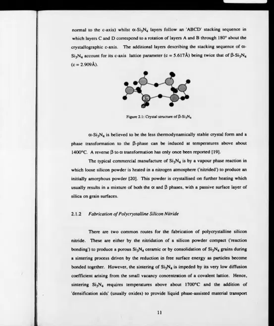
normal to the c-axis) whilst cx-Si3N4 layers follow an 'ABCD' stacking sequence in which layers C and D correspond to a rotation of layers A and B through 180° about the crystallographic c-axis. The additional layers describing the stacking sequence of a - Si3N4 account for its c-axis lattice parameter (c = 5.617A) being twice that of (J-Si3N4 (c = 2.909A).
Figure 2.1: Crystal structure o f 0 -S i3N4
0(-Si3N4 is believed to be the less thermodynamically stable crystal form and a
phase transformation to the 3-phase can be induced at temperatures above about 1400°C. A reverse 3 to a transformation has only once been reported [19].
The typical commercial manufacture of Si3N4 is by a vapour phase reaction in which loose silicon powder is heated in a nitrogen atmosphere ('nitrided') to produce an initially amorphous powder [20]. This powder is crystallised on further heating which usually results in a mixture of both the a and 3 phases, with a passive surface layer of silica on grain surfaces.
2.1.2 Fabrication o f Polycrystalline Silicon Nitride
There are two common routes for the fabrication of polycrystalline silicon nitride. These are either by the nitridation of a silicon powder compact ('reaction bonding') to produce a porous Si3N4 ceramic or by consolidation of Si3N4 grains during a sintering process driven by the reduction in free surface energy as particles become bonded together. However, the sintering of Si3N4 is impeded by its very low diffusion coefficient arising from the small vacancy concentration of a covalent lattice. Hence, sintering Si3N4 requires temperatures above about 1700°C and the addition of 'densification aids' (usually oxides) to provide liquid phase-assisted material transport
(see the following section). Additionally, grain consolidation is often assisted by external pressure application. In the absence of any additional pressure, an increased ambient nitrogen pressure is essential to avoid thermal decomposition of Si3N4 at sintering temperatures approaching the decomposition temperature of 1900°C under 0.1 MPa [21],
(i) Liquid Phase Sintering
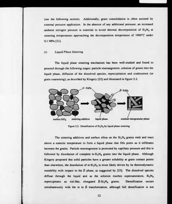
[image:27.595.20.577.14.672.2]The liquid phase sintering mechanism has been well-studied and found to proceed through the following stages: particle rearrangement, solution of grains into the liquid phase, diffusion of the dissolved species, reprecipitation and coalescence (or grain coarsening), as described by Kingery [22] and illustrated in figure 2.2.
Figure 2.2: Densification of Si3N4 by liquid phase sintering
The sintering additives and surface silica on the Si3N4 grains melt and react above a eutectic temperature to form a liquid phase that fills pores as it infiltrates between the grains. Particle rearrangement is promoted by capillary pressure and this is followed by dissolution of complete a-S i3N4 grains into the liquid phase. Although Kingery proposed that solid particles have a greater solubility at grain contact points than elsewhere, the dissolution of a -S i3N4 is more likely driven by its thermodynamic instability with respect to the 3 phase, as suggested by [23]. The dissolved species diffuse through the liquid and as the solution reaches supersaturation, Si3N4
reprecipitates as rod-like, elongated 3-Si3N4 grains. Densification occurs
necessarily accompanied by complete oc to 3 conversion [24]. Both these processes are controlled by atomic diffusion [23,25] at a rate found to be linearly dependent on the sintering temperature and the quantity o f the liquid phase. If (3-Si3N4 is present in the initial powder composition, particles precipitate on the coarser (3-Si3N4 grains and continuous grain growth to large, spherical grains ensues. A predominantly a-S i3N4 phase content is desirable in the starting powder in order to realise the optimal mechanical properties that arise from the fibrous microstructure of newly-formed J3- Si3N4 grains [26-28].
On cooling, the liquid phase is converted to a glassy or crystalline intergranular phase. Although the liquid phase is advantageous for sintering purposes, the properties of the residual phase (melting point, viscosity) strongly influence those of the final Si3N4 ceramic and lead to a degradation in high temperature strength and creep resistance. The glassy phase also tends to trap impurity ions present in the starting powders which may further reduce its viscosity.
(ii) Pressure-Assisted Sintering
Application of external pressure during sintering produces a marked increase in the densification rate [24,25] and results in generally stronger materials through a decrease in final porosity and use of lower sintering additive levels, hence a reduced intergranular phase content.
In the hot pressing process, sintering is carried out inside a graphite die with uniaxial pressure application, of typically 20-30 MPa, limited by the strength of the die. The uniaxial nature of the applied pressure causes some orientational alignment of elongated grains [29,30] and is responsible for differences in physical properties measured parallel and perpendicular to the hot-pressing axis.
2.1.3 Silicon Nitride Sintering Additive Systems
The conflicting roles of silicon nitride sintering additives, in providing a liquid phase sintering medium to the detriment of final material properties, has motivated much research to find sintering additives that form a more refractory intergranular
phase. Sintering additives can be divided into two classes, depending on whether or
not they form a 'solid solution' in the Si3N4 lattice.
(i) SiAlON Ceramics
The fabrication of SiAlON (or 'sialon') ceramics developed from the discovery that A120 3 sintering aids become absorbed into the 0-Si3N4 crystal lattice during the sintering process [32,33]. This takes place by substitution of Al3+ ions onto Si4+ sites, made possible by their similar ionic radii and is accompanied by substitution of O2' for N3' ions to maintain charge neutrality and a constant cation:anion ratio of 3:4. The solid solution of A120 3 expands the 3-Si3N4 crystal lattice into what is termed the 3'-Si3N4 lattice and reduces problems of degraded mechanical properties associated with a residual intergranular phase. An a ' sialon is also formed by the incorporation of interstitial metallic ions into the oc-Si3N4 lattice. A full review of the different sialon crystal structures can be found in reference [34].
The advantages of sialons are that they can be sintered to high density at normal atmospheric pressure and therefore, can be produced in the final component shape, reducing the need for mechanical machining. The sialon sintering mechanism is by solution and reprecipitation (as described for sintering Si3N4) and the densification rate can be similarly increased by addition of another oxide additive to lower the eutectic temperature and reduce the liquid phase viscosity.
(ii) Non-Sialon-forming additives
hot pressing with an Y20 3 additive. However, since the Y20 3 additive forms a more viscous liquid phase than that formed by MgO, increased sintering temperatures (above 1700°C) are required to reduce the viscosity so as not to inhibit particle rearrangement during sintering. External pressure application (by hot-pressing or HIPing) is also necessary for full densification of Si3N4 with an Y20 3 additive.
[image:30.595.5.572.18.667.2]E Q U IV A LE N T * OXYGEN
Figure 2.3: Phase relationships in the Si1N4-S i0 2-Y 20 1-YN system, after [39].
There are several possible yttrium silicate phases that may be formed on reaction with the surface S i0 2 on Si3N4 grains and these have been studied in relation to their properties as an intergranular residual phase [37-39]. Many Si-Y-O-N phases are unstable on oxidation, undergoing a volume expansion that is high relative to silicon nitride. When these phases are present in Si3N4 ceramics their oxidation behaviour induces internal stresses sufficient to catastrophically degrade the ceramic. However,
Lange et al. [38] found that materials fabricated within the Si3N4-Si2N20 -Y 2Si20 7
triangle of the phase-relation diagram (shaded in figure 2.3) have excellent oxidation resistance compared with other Si3N4 ceramics, explained by the compatible existence of Y2Si20 7 and S i0 2, the oxidation product of both Si3N4 and Si2N20 .
system, secondary phase oxide additives are often added to lower the eutectic temperature of the liquid phase and enhance the densification kinetics so that full densification may be achieved with lower sintering temperatures. Typical additive
systems are Y2O3-AI2O3 [40] in which some A1203 dissolves into the Si3N4 grains,
forming a sialon, Y2C>3-MgO [41] and Y20 3-Nd0 3 [42], Hirosaki et al. [43] studied the
effect of the addition of AI2O3, MgO, La203 and Nd203 secondary additives on the
Y203 additive system and found that whilst all these additional additives facilitated the
densification process, the addition of A1203 and MgO degraded the final mechanical
properties whereas the other systems showed comparable refractory behaviour to the single additive system.
2.2 DISPERSED-PHASE CERAMIC COMPOSITES
The microstructure of ceramic composites provides a means of absorbing crack propagation energy by interaction of the crack front with a secondary phase. This interaction leads to a reduction in the stress intensities around the crack tip and allows the material to tolerate a larger critical flaw size. As a result, the resistance to fracture is increased as the crack extends (known as 'R-curve' behaviour), enhancing the fracture
toughness and strength. The secondary phase may be a random dispersion of
particulates, platelets (flat discs), whiskers (short, needle-shaped filaments) or uniaxially-aligned fibres.
The creation of composites with macroscopic compositional variations is discussed in section 2.2.4.
Silicon nitride composites were developed from the need for the structural improvement of poly crystal line Si3N4 to expand the already excellent physical and
chemical properties that make Si3N4 an important engineering material. Silicon
carbide, a traditional abrasive, possesses similarly attractive properties to those of Si3N4 and so can effectively toughen silicon nitride ceramics without adversely affecting the desirable characteristics. Both Si3N4 and SiC are strongly covalent, refractory materials and typically exhibit the following properties: (i) high hardness (ii) good wear resistance (iii) strength retention over a wide range of temperatures (iv) low thermal
expansion and (v) good chemical stability in corrosive environments. Lange [45]
fabricated a SiC particulate-reinforced Si3N4 composite with twice the strength of monolithic Si3N4 at 1400°C. Continued research indicating the substantially improved mechanical behaviour of SiC-Si3N4 ceramics over monolithic Si3N4 has consistently been reported [46,47]. Much research is currently in progress to evaluate relative advantages of the different morphological forms of dispersed SiC phases.
2.2.1 Dispersed-Phase Composite Toughening Mechanisms
The toughening mechanisms exhibited by dispersed-phase composites are governed by the characteristics of the interface between the matrix and reinforcing particle, in the same way as for fibre-reinforced composites [48], which leads to enhanced toughness by providing relatively weak fracture paths that absorb energy without catastrophic failure. The strength o f the interfacial bonding is not easy to control during processing and this accounts for some deviations between predicted and observed toughening behaviour. Debonding of the matrix-dispersoid interface occurs when the interfacial fracture energy is exceeded by the propagating crack energy and is determined by (i) the relative orientation of the dispersoid to the crack and (ii) the ratio
of interfacial fracture energy to dispersoid fracture energy [49]. Toughening
(i) Crack Interaction with Dispersed Inclusions
The presence of secondary phase inclusions may promote toughening provided that they do not act as stress concentrators. Lange [50] described a 'crack bowing' toughening mechanism where the crack front becomes momentarily pinned between dispersed inclusions and bows out with a curved path that increases the crack length. Toughening is effected by absorption of the crack propagation energy as the new fracture surfaces are formed. However, the crack is able to move away from its pinning positions when the fracture stress of the dispersed phase is reached and failure occurs. Lange derived an expression [50] for the composite fracture energy and found that the resistance to fracture should increase with a decrease in the distance between inclusions (and hence, with a greater volume fraction of the inclusions).
(ii) Crack Deflection
Figure 2.4: Crack deflection by a dispersed phase (regular platelets)
Crack deflection takes place where weakened interfaces or residual stresses provide preferential, non-planar fracture paths around secondary phase inclusions in the matrix. As the crack plane changes its orientation relative to the applied stress, the
crack driving force is reduced and so further energy is required for continued
(I) and sliding (II) crack propagation modes. The degree of tilting depends on the position and orientation of the inclusion in the crack path. When adjacent inclusions are orientated such that the crack is required to tilt in opposite directions, the crack plane becomes twisted about an axis perpendicular to the crack front, propagating in opening (I) and tearing (111) modes. Faber and Evans assessed the angularly-dependent, local stress intensity factors at tilted and twisted sections of the crack front and predicted the toughening increments using the relationship
where Gc is the effective critical strain energy release rate (SERR) for the deflected crack, Gm is the SERR for an undeflected crack, <G> is the average SERR (considered to represent the average crack driving force) and Gcm is the critical SERR for an
undeflected matrix crack. Their predictions suggested that toughening by crack
deflection is dependent on the aspect ratio (length (radius) to width (thickness)) and volume fraction of dispersed-phase particles, but is not influenced by the particle size.
V olum e Fraction o f Dispersed Phase
Figure 2.5 : Predicted toughening increases from crack deflection around discs or rod-shaped inclusions as a function o f volume fraction and aspect ratio, R (adapted from [51])
Rods of high aspect ratio were expected to provide the greatest toughening, mainly by crack twisting whilst high aspect ratio discs can considerably improve toughness by initial crack tilting in addition to crack twisting. Spherical particles were expected to be the least effective in toughening by crack deflection on account of their low aspect ratio. At dispersed phase volume fractions much above 20% the effects of overlapping
(2.1)
Relative Toughness, Oc/OCJn
4 ____________________
R = 12
3
-2
particles were expected to inhibit further toughening increases as is shown by the asymptotic behaviour of the graphs in figure 2.5.
Liu et al. [52] adopted a similar approach to Faber and Evans to calculate the
crack deflection toughening due to rod-shaped whiskers. However, Liu et al.
considered that the densification of dispersed phase composites requires pressure- assisted sintering, typically hot-pressing for which uniaxial pressure application causes whisker alignment perpendicular to the pressing direction. Hence, Liu et al. treated the reinforcing phase as being randomly orientated in a two dimensional plane only and showed that the orientation of the whiskers (rods) to the advancing cracks also influences the toughening increment. From these calculations, borne out by experiment, the degree of crack deflection and hence, fracture toughness is significantly higher for a crack travelling perpendicular to the plane of aligned whiskers than for crack propagation within this plane.
(iii) Crack Bridging
Crack bridging is a prominent toughening mechanism in fibre-reinforced composites [48] and is also important in whisker and platelet-containing materials. Observations in whisker-reinforced ceramics [53] suggest that crack bridging may additionally inhibit grain boundary sliding at high temperatures. The bridging action, where separating crack surfaces are joined by particles of the reinforcing phase, is induced by partial debonding of the matrix-reinforcement interface in a 'bridging zone' created behind the crack tip [54]. As the applied stress is transferred from the matrix to
grain rupture pullout crack deflection and bridging

![Figure 2.3: Phase relationships in the Si1N4-Si02-Y20 1-YN system, after [39].](https://thumb-us.123doks.com/thumbv2/123dok_us/9866109.487793/30.595.5.572.18.667/figure-phase-relationships-the-si-si-system-after.webp)
![figure 3.8), using the equation derived by Evans and Charles [2, 141]](https://thumb-us.123doks.com/thumbv2/123dok_us/9866109.487793/73.595.3.571.16.665/figure-using-equation-derived-evans-charles.webp)