Efficient Use of Electronic Waste for CNC Machine
Kushal Verma
SRM IST (formerly known asSRM University) DH-85 Pallav Puram Phase 1,
Modipuram, Meerut - 250001
Ishita Gianchandani
SRM IST (formerly known asSRM University) Pocket i 126-C Dilshad Garden,
Delhi - 110095
Prankur Verma
JSS Academy of Technical Education, C-20/1, Sector-62,Noida-201301
DH-85 Pallav Puram Phase 1, Modipuram, Meerut - 250001
ABSTRACT
In order to minimize the cost of the CNC machine, this paper proposed an idea to recycle the waste material of the old computer system. The implementation of this paper consists of the followings: Arduino UNO R3 board, Stepper motors – for the motion of X and Y axes, mini Servo motor, L293D driver IC, Arduino Processing software (freeware), Inkscape software to create G-codes for the input data (freeware), any type of pen or pencil - as the main source of ink. This project is able to draw complex line drawings by plotting the coordinates using a simple algorithm. Plotting of coordinates is cultured within G-codes prepared by a software after which it is transferred to the microcontroller by which the motor mechanism is instructed to draw the image or text data, motor mechanism includes X-and Y-axes that can each work independently, yet simultaneously.
Keywords
Stepper Motor, CNC Machine, G-codes
1.
INTRODUCTION
The project is the opportunity to show the world the work that has been keeping many geeks and enthusiasts involved day and night. Computer Numerical Control is an advanced form of soft automation developed to control the motion and operation of machine tools. Their fabrication includes certain advantages like efficiency, flexible, low cost, less working time and fewer losses in production [1]. This printer is flexible; it could be made to work like a laser engraver for engraving texts or images on any hard surface or as a compact milling machine also if the pen is replaced with a drill machine. Similarly, if the pen is replaced with an embroidery needle then it could create some cool and awesome embroidered patterns and logos on any cloth material. Various modifications like including one more axis or increasing the printing area can be made without rewriting the algorithm of this machine [1-7].
Pinhiero et al. (2016) [1] discussed on the design of the three-axis plotter using stepper motors and making them at relatively cheaper costs and with minimal labor. Madekar et al. (2016) [3] discussed the much broader application of CNC machines. He developed a low cost automatic mini CNC machine for PCB drawing and drilling. He used the FTDI module, ATMEGA328, easy drivers 16MHz crystal oscillator for much more flexible operation and flexibility. Kashif et al. (2017) [6] discussed the design implementation of the CNC machine with multi-tool attachment. He explains the axis coordination system, tells about the detailed mechanism of the components, their driving mechanisms. Prince et al. (2017) [8] explained the various software required starting from the input data parsing till the output data implementation, he explained
how these software’s works and adds up together to give exceptional results. It has been concluded that the Bresenham’s Line Algorithm is used for plotting in the CNC plotter.
From all of these research papers, necessary guidelines were followed and concepts were made clear prior to the manufacturing. All these research papers helped in molding this project and giving it a nice design and well-implemented algorithms. Use of electronic components was carefully accomplished which helped in their proper function. This project is a prototype that is enough to explain how the capabilities of these hardware’s and software can be grown to such an extent that it can very well replace many technologies that are costlier to implement and function which is going to benefit various companies as well as graduate youths. The parts of this project are all extracted from old damaged spare parts of a computer CPU unit. The construction is very simple and sturdy. Indeed, it is highly flexible to various applications. Placing laser or embroidery needle we can either etch data on metallic or other hard surfaces or create beautiful embroidered designs on any type of cloth material. The programming in the CNC machine incorporates all the exacting, high-speed movements needed to produce the object, and it enables detailed customization. The rest of this research paper includes the problem statement, results, and discussion, and finally, the conclusion carried out for building this project, giving it the desired shape.
2.
PROBLEM STATEMENT
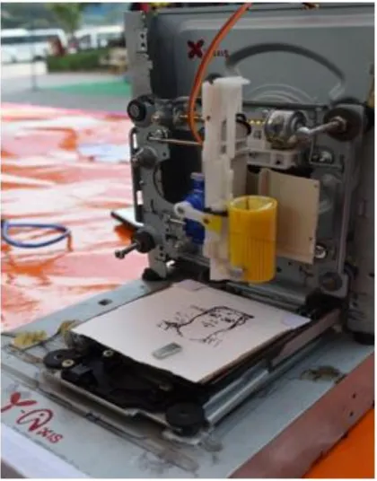
The objective of this project is to overcome the biggest disadvantage i.e. cost of printing inks so building one that is quite cheap and delivering remarkable output to the user and provide them a creative environment to see how machine interprets their commands and do something in real time could be a milestone [7]. It consists of stepper motors (extracted from old CD drives) came out to be the fundamental idea for the project, this device can draw images (logo designs, PCB etching designs, etc.) and texts in a small range canvas and data is being loaded from any computer machine.
There is a pool of printers in the market which can print any data but this CNC machine could prove to be the initial step to fabricate something to everyone for a non-virtual i.e. real-time environment to interact with machines and save the construction and printing costs. The expected output of this machine is beguiling.
15 1. Type of inputs
2. Structure complexity
3. Apparatus and construction
[image:2.595.67.563.127.360.2]Generally, 3D printing is used to produce prototypes and has relatively low speed compared to CNC machining. Because of this, it is not efficient for producing large quantities.
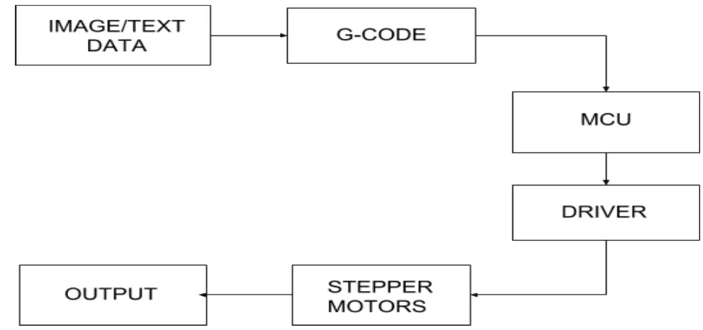
Fig 1: Block Diagram of CNC printer
3.
PROPOSED STATEMENT
The intent of development of this model is to first of all find out a way to reduce cost of inks used in general purpose printers and then embedding programming knowledge to build something that could be used to print or draw any text, image, logo, etc. directly from a pen or pencil onto a paper. The expectation is that this project is going to help out many colleges going undergraduates as well as school going students and other professionals to see how the programming languages that students learn in their academic years could make a machine come alive and analyze how machine interprets our commands and function accordingly. With the increasing demand for the use of CNC plotters in universities and laboratories, a cheap and less complex design is an absolute need.
1. The very first step includes the user feeding the input data into the vector graphics software i.e. INKSCAPE, where the input data could be any vector image, text input, solidly filled image, sketched image, etc.
2. G-codes are the computer numerical machine language codes generated by plotting the
respective coordinates of input data. These G-codes are used to control the feed rate, coordination, and speed of axes of the motors. It guides whether the motor has to move clockwise or anticlockwise and the duration for which it has to be in motion. The second step involves generation of G-code through Inkscape software because manually writing G-codes is a tricky job, therefore, this project generates this using python scripting language. The parameters generated by G-code are required by the machine in order to maintain coordination for printing the input data.
3. The third step is feeding the prepared G-codes into the Arduino for the main action. For this, the project uses a GRBL platform to feed data and on show the dynamic commands being transferred in real time action.
Fig 2: Working Model
The various components utilized for the fabrication has been given in Table 1:
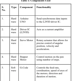
Table 1: Components Used
S. No.
Type Component Functionality
1. Hard
ware
Arduino UNO
Send synchronous data inputs to the L293D driver IC.
2. Hard
ware
Driver IC (L293D)
Acts as a current amplifier
3. Hard
ware
Servo Motor Rotary actuator that allows for precise control of angular position, velocity and acceleration.
4. Hard
ware
Stepper Motor
Control motion on the pen using number of steps.
5. Soft
ware
G-Code Controls the feed rate, coordination, speed of axes of the motors, direction and duration of motion.
3.1
Software Implementation
3.1.1
Inkscape 0.48.5
To make G-code files that are compatible with this CNC machine user have to use the Inkscape. Inkscape is professional quality vector graphics software which runs on Windows, Mac OS X and Linux. It is used by design professionals and hobbyists worldwide, for creating a wide variety of graphics such as illustrations, icons, logos, diagrams, maps and web graphics. Inkscape uses the W3C open standard SVG (Scalable Vector Graphics) as its native format, and is free and open-source software.
To create G-code of an image, the file must have a transparent background. The image should be dragged into
the selected area then select “trace bitmap” from drop down window to create a transparent image. Scans are selected as 8 and “Edge detection” is selected to create black & white image. After adding this transparent image in the predefined area, user need to select “object to path” command to create the G-code file of the selected image.
3.1.2
Processing
Processing is open source programming language software which is used for electronic drawings. GTCRL processing program is used to send G-code file from user interface to CNC plotter. The port of Arduino UNO is selected after running GCTRL program followed by uploading the desired G-code. Immediately CNC machine will start sketching selected G-code file, sketching can be stopper by pressing ‘X’ button and both the axis can be moved to their home locations i.e. coordinates ‘0’ by pressing ‘H’ button.
3.1.3
Coding
Bresenham’s algorithm is used for plotting in the CNC plotter. A part of the algorithm is explained below: void line(int x, int y, int x1,int y1) {
int dx = abs(x1-x), sx = x<x1 ? 1 : -1; int dy = abs(y1-y), sy = y<y1 ? 1 : -1; int err = (dx>dy ? dx : -dy)/2, e2; for(;;){
setPixel(x,y);
if (x==x1 && y==y1) break; e2 = err;
if (e2 >-dx) { err -= dy; x += sx; } if (e2 < dy) { err += dx; y += sy; } }
}
Two stepper motors are used to control X and Y axis, and a servo motor is used to control the Z axis. ‘x’ and ‘y’ above are default home positions whereas ‘x1’ and ‘y1’ are new locations fetched from the G-codes.
4.
RESULTS AND DISCUSSION
[image:3.595.60.312.308.592.2]17 improved with high powered motors and large printing
span area.
The biggest advantage behind making this model is being the cost-effectiveness, one can ask why there is the need for making this CNC printer when there are other printers available in the market. An answer to the question is the fact that, one can have printers but can’t have it at this much affordable price. This factor makes this machine somewhat unique from all other printers; anyone can easily make this machine a real icebreaker where implementation of theoretical knowledge comes into practical implementation. This project is designed with a very simple construction scheme and can be carried anywhere without many efforts. A very simple algorithm is implemented which can handle any type of modifications made within the machine without rewriting it. Using open source and user-friendly software’s were preferred.
[image:4.595.334.531.67.455.2]Though the archetypal circuit is very complicated to handle so, it is preferred to create a compact one i.e. by minimizing the jumper wires, can easily be stick to the back of the machine where the network of wires is assembled. Compact wiring of the circuit is represented in fig. 4 and fig. 5. Mechanical design of the CNC printer is demonstrated below:
Fig 3: Mechanical Implementation
Fig 4: Front-view of the circuit
Fig 5: Back-view of the circuit
It consumes low power and works with precision which could be altered accordingly by the user within the C++ code. In addition to the personal use for small-scale application in educational institutes, this project can be resourceful to all generations of the society including kids, youth, and elderly people. In favor of the environment, it is ecological in terms of electricity, ink and paper usage. It can be deduced that this CNC Project has wide applications in all spheres of society in an economical approach. However, the cost is an investment in long-term savings, efficiency, client retention and a reputation for quality and reliability. While CNC machining might create tremendous, new opportunities for all kinds of people in society including youths, it might lead to less conventional machining and ultimately, some unemployment. However, most experts do not agree that manual skills will become obsolete. In fact, some think conventional machining will thrive through small and specialty projects.
5.
CONCLUSION
[image:4.595.81.291.339.607.2]line for the future of this model, saving money and time is one of the most popular benefits of CNC machining. Design retention, once a design has been loaded into the CNC machining software and a perfect prototype has been created, the program can easily retrieve the design to run it and create that object. Low maintenance, the g-code based software will automatically update itself when needed, and generally, do not require much services.
6.
ACKNOWLEDGMENTS
The authors wish to thanks all those who helped in successful development of this project: Dr. R. P. Mahapatra (H.O.D, CSE), Mr. Partha Sarathi Chakraborty (Assistant professor, CSE), Mr. Naresh Sharma (Assistant professor, CSE), Mr. M. Mohan (Professor, CSE) and also like to thank Department of Computer Science and Engineering, SRM-IST (formerly known as SRM University).
7.
REFERENCES
[1] Pinheiro Aneeta. (April 2016). Mini CNC Plotter, in International journal of innovative research in electrical, electronics and control engineering, Vol. 4, (pp. 187-188).
[1] Pandey Udit, Sharma S.R. (June 2017). Model and Fabrication of CNC Plotter Machine, inInternational Journal of Advanced Research in Computer and Communication Engineering, Vol. 6.
[2] Madekar Kajal J., Nanaware Kranti R., Phadtare Pooja R., Mane Vikas S. (February 2016). Automatic mini cnc machine for pcb drawing and drilling, in International journal of Engineering and Technology, Vol. 3, No. 2, (pp. 1106-1110).
[3] Linggarjati, Jimmy, Hedwig R. (2013). Manually interchangeable heads of homemade computer numerical control (cnc) machine, in Internetworking Indonesia journal, Vol. 1.1.
[4] Pabolu V.K., Srinivas K.N.H. (2010). Design and implementation of a three -dimensional CNC
machine, in Int. J. Computer Science and Engineering, Vol. 2, (pp. 2567-2570).
[5] Kashif Syed Ikhtar, Madani Syed, AM Siftain Khan, Shariff Mohammed Umar, Rathnakar G., Kumar S. (December 2017). Computer numerically controlled multi operational machine, in International journal of research in aeronautical and mechanical engineering, (pp. 553-560).
[6] Jodh Gautam, Sirsat Piyush, KakdeNagnath, Lutade Sandeep. (Feb-Mar 2014). Design of low cost CNC drilling machine, in International Journal of engineering research and general science, Vol. 2, (pp. 1405-1415).
[7] Khan Mohammad Kamruzzaman, AnsaryMuhsi Al-Mukaddem, Mondol Abu Shafwan. (January 2017). Implementation of low cost CNC plotter using spare parts, in International journal of Engineering trends and technology, Vol. 43, Number 6, (pp. 333-339)
[8] Zhang Xiaohua, Xu Bingji, (2010). Research on stepper motor control based on single chip and serial communication, in 8th World Congress on Intelligent control and automation, Jinan, (pp. 3019-3023).
[9] Sutarman, EdiHermawanHaryono, Sarmidi, (2017), Computer Numerical Control (CNC) Milling and Turing for Machining Process in Xintai Indonesia, in Quest Journals Journal of Research in Mechanical Engineering, Vol. 3, Issue 5, (pp. 01-07).
[10]Rajput Rajat, Dr. Sarathe A.K., (2016), Comparative study of CNC Controllers used in CNC Milling Machine, in American Journal of Engineering Research (AJER), Vol. 5, Issue 4, (pp. 54-62).