Evaluation of Tasks Allocation, Scheduling and Ranking
Techniques in a Cloud Computing Environment
Dina Darwish
Associate Professor
The International Academy for Engineering and Media Science
Egypt, Multimedia and Internet Department
ABSTRACT
Cloud computing presents an architecture that delivers computing services via the internet on demand and payed per use of a pool of resources that are shared, such as networks, storage, servers, services and applications, without having to acquire them. Cloud computing reduces managing cost and time for organizations. Many industries, such as banking, healthcare and education are shifting to the cloud, due to the effectiveness of services delivered by the pay-per-use concept depending on the resources, such as processing power utilized, transactions performed, bandwidth consumed, data transmitted, or storage space occupied etc. Cloud computing is considered as a technology that relies completely on the internet, where client data is saved and kept in the data center of a cloud supplier. The goal of this paper is to implement and evaluate different allocation, scheduling and ranking techniques, where, different methods for the allocation, scheduling and ranking of workflow tasks are proposed, implemented and evaluated. Simulation was performed on these techniques, and the results were analyzed to find the best technique in terms of efficiency and performance in reducing completion time and cost.
General Terms
Cloud Computing
Keywords
Cloud Computing, Cloud Architecture, Cloud Platform, Tasks Scheduling, Tasks Ranking.
1.
INTRODUCTION
Cloud Computing is considered as a distributed architecture that performs server resources centralization for the goal of presenting a scalable platform to provide on demand computing resources and services, and internet service suppliers provide costumers high speed broadband to access the internet. Cloud service suppliers provide cloud platforms for their customers to utilize and build their web services. Cloud computing constitute a model for allowing suitable, on-demand network access to a shared pool of configurable computing resources such as networks, servers, storage, applications, that can be rapidly reserved and released with minimal management effort. Cloud providers present three types of services; i.e., Software as a Service (SaaS), Platform as a Service (PaaS) and Infrastructure as a Service (IaaS). Besides, cloud represents a metaphor to define web as a space, where computing is preinstalled and exists as a service; meaning that data, operating systems, applications, storage, and processing power reside on the web ready to be shared. From users’ point of view, cloud computing presents a Pay-per-Use-On-Demand mode, that can easily reach shared IT resources via the Internet. Though, the IT resources include network, server, storage, application, service and so on, and they can be applied with much quick and easy manner and
less management and interactions with service providers. Cloud computing may enhance the availability of IT resources, and provides many advantages over other computing techniques. Users can utilize the IT infrastructure with Pay-per-Use-On-Demand mode; as this may benefit and reduce the cost for buying the vacant physical resources. For these various reasons, organizations desire to shift towards IT solutions, that contain cloud computing, since they just need to pay for the resources on consumption basis. Also, organizations can easily satisfy the requirements of varying markets to confirm that they are responding to customers’ needs [1]. Cloud computing emerged as a business necessity, being described by the idea of just using the infrastructure without managing it. Although this idea appeared initially in the academic area, but recently, it was transferred into industry by companies like Microsoft, Amazon, Google, Yahoo! and Salesforce.com. So, it is easier for new beginners to enter the market, as the cost of the infrastructure is diminished. Also, developers can focus on the business value instead on the initial budget. The clients of commercial clouds have the ability to rent computing power (virtual machines) or storage space (virtual space) dynamically, depending on the needs of their business. With the discovery of this technology, users can reach heavy applications through lightweight portable devices, like mobile phones, PCs and PDAs. Clouds form the new direction in the evolution of the distributed systems, as the predecessor of cloud was the grid. The user does not need special knowledge or expertise to manage the infrastructure of clouds; as it offers only abstraction. Also, it can be implemented as a service of an Internet with high scalability, higher throughput, quality of service and high computing power. Cloud computing suppliers deliver common online business applications, which are reached from servers via web browser [2].
Several studies were performed to analyze cloud computing related issues and challenges [3-7], other studies were done on computing variables and services inside a cloud environment [8-10].
The workflow tasks allocation, scheduling and ranking on different computing environments has been intensively studied [11, 12] due to its significance on performance. There exist several approaches that are considered for the achievement of allocation, scheduling and ranking for workflow tasks.
In this paper, several approaches for organizing tasks allocation, scheduling and ranking are presented, and their parts are described in details. The idea of studying this area is derived from the need to solve the previously mentioned problems, and to benefit from previous work implemented in this area.
cloud computing architecture was explained. In section 3, proposed workflow tasks scheduling and ranking were explained. In section 4, simulation and experimental results were analyzed and evaluated. In section 5, conclusions and future work are mentioned.
2.
CLOUD COMPUTING
ARCHITECTURE
[image:2.595.110.260.246.413.2]Cloud services are generally grouped into three categories: Software as a Service (SaaS), Platform as a Service (PaaS), and Infrastructure as a Service (IaaS), that are represented by a given cloud infrastructure. Figure 1 illustrates a cloud reference architecture described in research [13], that creates the most important security-relevant cloud components explicit, and provides an abstract overview of cloud computing for security issue analysis.
Fig 1: The cloud reference architecture
The cloud services can be summarized as follows [14]. Software-as-a-Service (SaaS): SaaS may be seen as a process, by which Application Service Provider (ASP) offer various software applications over the Internet. This makes the customer get rid of installing and executing the application on own computer, and also prevents the huge load of software maintenance; continuing operation, safeguarding and support [15]. SaaS vendor takes responsibility for applying and controlling the IT infrastructure (servers, operating system software, databases, data center space, network access, power and cooling, etc) and processes (infrastructure patches/upgrades, application patches/upgrades, backups, etc.) needed to run and manage the full solution. SaaS provides a complete application presented as a service on demand. Platform as a Service (PaaS): ―PaaS is considered as the delivery of a computing platform and solution stack as a service without software downloads or installation for developers, IT managers or end-users. It offers an infrastructure with a high level of integration to deploy and test cloud applications. So, Paas represents a development platform supporting the full ―Software Lifecycle‖. The user does not deal with the infrastructure (including network, servers, operating systems and storage), but he manages deployed applications and, possibly, their configurations. Infrastructure as a Service (IaaS): Infrastructure as a service (IaaS) is related to the sharing of hardware resources for processing services using Virtualization technology. Its main objective is to make resources such as servers, network and storage more readily accessible by applications and operating systems. Thus, it offers basic infrastructure on-demand
services and using Application Programming Interface (API) for interactions with hosts, switches, and routers, and the capability of adding new equipment in a simple and transparent manner. In general, the user does not manage the underlying hardware in the cloud infrastructure, but he controls the operating systems, storage and deployed applications. The service provider owns the equipment and is responsible for housing, running and maintaining it. The client typically pays on a per-use basis.
There are also four different cloud deployment models namely Private cloud, Public cloud, Hybrid cloud and Community cloud.
Private cloud: They can be owned or leased and managed by the organization or a third party and exist at on-premises or off-premises. It is more expensive and secure when compared to public cloud.
Public Cloud: A cloud infrastructure is provided to many customers and is managed by a third party and exist beyond the company firewall. Multiple enterprises can work on the infrastructure provided, at the same time and users can dynamically provision resources. These clouds are fully hosted and managed by the cloud provider and fully responsibilities of installation, management, provisioning, and maintenance. Customers are only charged for the resources they use.
Hybrid Cloud: A composition of two or more cloud deployment models, linked in a way that data transfer takes place between them without affecting each other. These clouds would typically be created by the enterprise and management responsibilities would be split between the enterprise and the cloud provider. In this model, a company can outline the goals and needs of services [16]. A well-constructed hybrid cloud can be useful for providing secure services such as receiving customer payments, as well as those that are secondary to the business, such as employee payroll processing.
Community Cloud: Infrastructure shared by several organizations for a shared cause and may be managed by them or a third party service provider and rarely offered cloud model.
These clouds are normally based on an agreement between related business organizations such as banking or educational organizations. A cloud environment operating according to this model may exist locally or remotely. An example of a Community Cloud includes Facebook which is showing in Figure 2 described in research [14], which represents high level view of cloud computing architecture.
Fig 2: High Level View of Cloud Computing Architecture Applications
Google Apps Salesforce.com YouTube Facebook
Google apps
Software Framework/ Programming environment Google App Engine Java/Python/.Net Microsoft Azure
Google apps
VM1
m
1
Virtual Machines Amazon EC2, EC3 CPU Memory Server
Disk Bandwidth Storage Network VM2
12
SaaS PaaS
IaaS
Data Centers
VMn IaaS
PaaS SaaS
Facilities Front end Network
Cloud (web)applications
Cloud software environment
C Cloud software infrastructure
Kernel (OS/apps)
Hardware User
Se
rv
ic
es
an
d
A
P
Is
M
an
ag
em
ent
a
cc
ess
M
A
A
m
ec
ha
ni
sm
s
P
ro
du
ce
r
Computational resources
Storage Communication
Service customer
[image:2.595.352.483.602.684.2]3.
TASKS ALLOCATION,
SCHEDULING, AND RANKING
TECHNIQUES IN CLOUD
COMPUTING
In this paper, some techniques for tasks allocation, scheduling and ranking are proposed and tested. First, the datacenters’, the hosts’, the virtual machines’, and the cloudlets’ characteristics implemented, are described, then, the used techniques are described. The implemented datacenters’ characteristics are as follows: architecture="x86";
os = "Linux";
vmm = "Xen";
time_zone = 5.0; // time zone this resource located
cost = 3.0; // the cost of using processing in this resource
costPerMem = 0.05; // the cost of using memory in this resource
costPerStorage = 0.07; // the cost of using storage in this resource
costPerBw = 0.1;
The implemented hosts’ characteristics are as below:
ram = 8000; //8GB
bw = 10000; // 10000 kbits/sec
storage = 1000000; // 1 teraByte = 1000 GB
The implemented virtual machines’ characteristics are given below: diskSize = 20000; //image size (MB)
ram = 2000; //vm memory (MB)
mips = 1000;
bandwidth = 1000;
vcpu = 1; //number of cpus
vmm = "Xen"; //VMM name
The implemented cloudlets’ characteristics are described as follows: cloudletLength = 20000; // but it varies during simulation
cloudletFileSize = 300;
cloudletOutputSize = 300;
pesNumber = 1;
UtilizationModel = UtilizationModelFull();
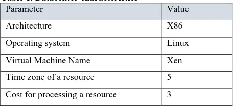
[image:3.595.53.281.662.767.2]The datacenter characteristics are summarized in Table 1. The Hosts characteristics are mentioned in Table 2. The virtual machines’ characteristics are mentioned in Table 3. The cloudlets’ characteristics are mentioned in Table 4.
Table 1. Datacenter characteristics
Parameter Value
Architecture X86
Operating system Linux
Virtual Machine Name Xen
Time zone of a resource 5
Cost for processing a resource 3
Cost of using memory for this resource 0.05 Cost of storing the resource 0.07 Cost of bandwidth for this resource 0.1
Table 2. Hosts characteristics
Parameter Value
RAM 8 GB
Bandwidth 10000 kbits/sec
Storage 1 Terabyte
Table 3. Virtual Machines characteristics
Parameter Value
Disk Size 20000 MB
RAM 2 GB
Million instructions per second (speed) 1000
Bandwidth 1000 kbits/sec
Cost for processing a resource 3
Number of vCPUs 1
Virtual Machines Names Xen
Table 4. Cloudlets characteristics
Parameter Value
Cloudlet Length of instructions
Varying from 2000 to 20000
Cloudlet file size 300 Kbytes
Cloudlet output size 300 Kbytes
core CPU number 1
Utilization Model Full Utilization Model
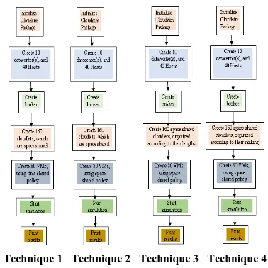
These techniques are described below, and their flowcharts are illustrated in Figure 3:
The first proposed model is composed of 10 datacenters, each has 4 hosts, this means, there are 40 hosts. Each host possesses 2 virtual machines, this means, there are 80 virtual machines. There exist 160 cloudlets variable sized randomly used inside these datacenters. Cloudlets are space shared, and virtual machines are time shared. This means that cloudlets are organized equally according to available space; and all cloudlets have the same space. Also, the virtual machines are allocated equally depending on time; so that all virtual machines have the same amount of time.
The third proposed model depends on the presence of 10 datacenters, each datacenter has 4 hosts, hence, there exist 40 hosts. Each host has 2 virtual machines, meaning that, there exist 80 virtual machines. Besides, there exist 160 cloudlets variable sized randomly implemented inside these datacenters. Cloudlets are space shared, and virtual machines are space shared. This means that cloudlets are allocated equally depending on available space; then, all cloudlets have the same space. And, the virtual machines are allocated equally according to space; so that all virtual machines possess the same amount of space, but cloudlets, representing tasks and services, are executed based on their size, using the technique of smallest comes first, in other words, smaller cloudlets in size are executed first.
The fourth proposed model is based on the presence of 10 datacenters, each one possesses 4 hosts, meaning that, there are 40 hosts. Each host has 2 virtual machines, meaning that, there exist 80 virtual machines. And, there are 160 cloudlets variable sized randomly used in these datacenters. Cloudlets are space shared, and virtual machines are space shared. Meaning that, hosts are organized equally depending on available space; and all cloudlets take the same space. Also, the virtual machines are allocated equally according to space; so that all virtual machines have the same amount of space. In this technique, cloudlets are executed depending on their priority or ranking. It means that every cloudlet is assigned a priority, and based on its priority it is ordered and executed, meaning that; if it has a high priority, it is executed before cloudlets with lower priorities, and if it has a low priority, it is executed after other higher priority cloudlets.
Each one of the proposed techniques is implemented, analyzed and tested inside the Cloudsim software. The Cloudsim is a specialized program used to simulate cloud solutions, since, it provides the ability to execute new techniques in cloud computing. The Cloudim program is described, and the obtained results are analyzed in the following section. Implementation steps of the proposed techniques in the cloudsim are mentioned below:
1. Initializiation of the Cloudsim package, It should be called before creating any entities
2. Create Datacenter(s), including datacenter characteristics, HostList, Processing element List, and defining policy for virtual machines allocation and scheduling.
3. Create broker
4. Create cloudlets, and define the workload, and their organization if any
5. Create Virtual machines, and define the procedure for task scheduling algorithms
6. Start the simulation, including automated process, handled through descreted event simulation engine
7. Print results when simulation is over, including outputs
[image:4.595.333.522.68.257.2]Technique 1 Technique 2 Technique 3 Technique 4
Fig 3: The proposed techniques flowcharts
4.
SIMULATION RESULTS
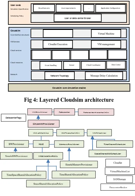
Simulation are accomplished using Cloudsim 3.0.3 [17], which is an important program for performing cloud computing solutions. Figure 4, which is described in paper [18] illustrates the layered implementation of the CloudSim software framework and architectural components.
CloudSim gives novel support for modeling and simulation of virtualized Cloudbased data center environments like, dedicated management interfaces for VMs, memory, storage, and bandwidth. CloudSim layer deals with the instantiation and execution of core entities (VMs, hosts, data centers, application) during the simulation period. This layer is able to concurrently instantiate and transparently manage a large scale Cloud infrastructure composing of thousands of system components. Also, it manages the fundamental issues such as provisioning of hosts to VMs based on user requests, managing application execution, and dynamic monitoring. A Cloud provider, that analyzes to study the efficiency of various policies in allocating its hosts, may need to utilize its strategies at this layer by programmatically expanding the core VM provisioning functionality. There exist a big difference at this layer on how a host is allocated to different competing VMs in the Cloud. A Cloud host can be concurrently shared among a number of VMs that process applications depending on user-defined QoS specifications. The top layer in the simulation stack is the User Code, that provides configuration related functionalities for hosts (number of machines, their specification and so on), applications (number of tasks and their requirements), VMs, number of users and their application types, and broker scheduling policies. A Cloud application developer can create a mixture of user request distributions, application configurations, and Cloud availability scenarios at this layer, and make robust tests depending on the custom Cloud configurations already used within the CloudSim.
development of best practices in all the critical aspects related to Cloud Computing.
Cloudsim is composed of a sum of classes to accomplish simulation. Cloudsim design class diagram is shown in Figure 5, which is described in paper [19], and it shows the fundamental classes of Cloudsim utilized during simulation, and these classes are forming the building blocks of the simulator. These classes are explained below:
Datacenter. This class models the core infrastructure level services (hardware, software) presented by resource providers in a Cloud computing environment. It contains a set of compute hosts (blade servers) that can be either homogeneous or heterogeneous in relation to their resource configurations (memory, cores, capacity, and storage). Every Datacenter component begins a generalized resource provisioning component that utilizes a set of policies for allocating bandwidth, memory, and storage devices.
DatacenterBroker. This class models a broker, that has the role of mediating between users and service providers based on users’ QoS requirements, and implements service tasks across Clouds. The broker acting on behalf of users determines convinient Cloud service providers through the Cloud Information Service (CIS), and negotiates with them for an allocation of resources that satisfies QoS needs of users. The researchers and system developers must expand this class to perform experiments with their custom developed application placement policies.
SANStorage. This class models a storage area network, that is usually available to Cloud-based data centers for saving large amounts of data. SANStorage utilizes a simple interface that can be used to generate storage and retrieval of any amount of data, at any time based on the availability of network bandwidth. Accessing files in a SAN at run time causes additional delays for task unit execution, due to time elapsed for transferring the required data files through the data center internal network.
VirtualMachine. This class models an instance of a VM, whose management during its life cycle depends on the responsibility of the Host component. A host can simultaneously start multiple VMs and determine cores based on predefined processor sharing policies (space-shared, time-shared). Every VM component has access to a component that saves the characteristics related to a VM, such as memory, processor, storage, and the VM’s internal scheduling policy, which is expanded from the abstract component named VMScheduling.
Cloudlet. This class models the Cloud-based application services (content delivery, social networking, business workflow), which are commonly implemented in the data centers. CloudSim represents the complexity of an application in terms of its computational requirements.
BWProvisioner. This is an abstract class, that models the provisioning policy of bandwidth to VMs that are implemented on a Host component. The function of this component is to be responsible for the allocation of network bandwidths to set of competing VMs implemented across the data center. Cloud system developers and researchers can expand this class with their own policies (priority, QoS) to satisfy the requirements of their applications.
MemoryProvisioner. This is an abstract class, that represents the provisioning policy for allocating memory to VMs. This component determines policies for allocating physical
memory spaces to the competing VMs. The execution and deployment of VM on a host is important only if the MemoryProvisioner component determines that the host has the amount of free memory, that is requested for the new VM deployment.
VMProvisioner. This abstract class provides the provisioning policy that a VM Monitor uses for allocating VMs to Hosts. The chief functionality of the VMProvisioner is to select available host in a data center, which meets the memory, storage, and availability requirement for a VM deployment. The default SimpleVMProvisioner utilization delivered with the CloudSim package allocates VMs to the first available Host that is satisfying the stated requirements. Hosts are considered for mapping in a sequential order. More complicated policies can be easily used inside this component to achieve optimized allocations, like, choosing hosts depending on their ability to meet QoS requirements, like response time, budget.
[image:5.595.317.535.329.644.2]VMMAllocationPolicy. This is an abstract class utilized by a Host component that models the policies (space-shared, time-shared) needed for allocating processing power to VMs. This class can easily be overridden to meet application specific processor sharing policies.
Fig 4: Layered Cloudsim architecture
Fig 5: Cloudsim class design diagram
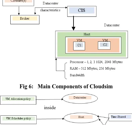
Cloudsim architecture is composed of several components; datacenter(s), connected to CIS (cloud information service), which in turn is connected in both directions to a broker using datacenter characteristics. Cloudlets go to the broker, then data flow from the broker to the datacenter or to the CIS. Each datacenter includes host(s). A Host carries virtual machine(s), which each one of them possesses a processor, a RAM and a bandwidth. The main components of the Cloudsim are illustrated in Figure 6, as shown below. Also, the Virtual Machine allocation policy is provided in the datacenter, the
VMProvisioner Datacenter Datacentercharacteristics DatacenterTags
SimpleVMProvisioner
VirtualMachine VMCharacterictics VMScheduler
Host MemoryProvisioner
BWProvisioner
SpaceSharedVMScheduler TimeSharedScheduler
VMAllocationPolicy
SimpleBWProvisioner Simple
SimpleMemoryProvisioner
TimeSpaceSharedAllocationPolicy
SpaceSharedAllocationPolicy
TimeSharedAllocationPolicy
Cloudlet
VirtualMachineList
SANStorage
DatacenterBroker
Cloudsim core simulation engine
Network Topology Message Delay Calculation
Event Handling Sensor Cloud Coordinator Data Center
Virtual Machine
Cloudlet Execution VM management
VM
provisioning AllocationCPU Memory Allocation
Storage Allocation
Bandwidth Allocation
A,location
User code
Simulation Specification Scheduling Policy
Cloudsim
User interface structures VM Services Cloud services Cloud resources Network
Cloudlet
User or data center Broker
virtual machine scheduler policy is determined in the host, and the cloudlet scheduler policy is determined in the Virtual Machine. The virtual Machine scheduler policy and the cloudlet scheduler policy can be time shared or space shared. Figure 7 shows VM allocation and scheduler policy and cloudlet scheduler policy.
Fig 6: Main Components of Cloudsim
Fig 7: shows VM allocation and scheduler policy and cloudlet scheduler policy
The time-shared and space shared policy and how they work, are going to be explained in the following section. The Virtual Machine Provisioner component is responsible for allocation of application-specific VMs to Hosts in a Cloud-based data center. This component provides a number of custom methods for researchers, that helps in utilization of new VM provisioning policies depending on optimization goals (user centric, system centric). The default policy used by the VM Provisioner is a straightforward policy that allocates a VM to the Host in First-Come-First-Serve (FCFS) basis. The system parameters, like the needed number of processing cores, memory and storage as requested by the Cloud user create the basis for such mappings. Other complicated policies can be defined by the researchers depending on the infrastructure and application requirements.
For each Host component, the allocation of processing cores to VMs is performed depending on a host allocation. The policy considers how many processing cores will be delivered to each VM, and how much of the processing core's capacity will effectively be delivered for a given VM. It is possible to assign specific CPU cores to specific VMs (a space-shared policy), or to dynamically distribute the capacity of a core among VMs (time-shared policy), and to assign cores to VMs on demand, or to determine other policies.
Each Host component begins a VM scheduler component, that utilizes the space-shared or timeshared policies for allocating cores to VMs. Cloud system developers and researchers can expand the VM scheduler component for experimenting with more custom allocation policies. Figure 8 illustrates the different scheduling policies in the task execution, described in research [18].
Fig 8: Different scheduling policies in the task execution: (a) Space-shared for VMs and tasks, (b) Space-shared for VMs and time-shared for tasks, (c) Space-shared for VMs and time-shared for tasks, (d) Space-shared for VMs and
tasks.
[image:6.595.61.272.146.347.2]Cloudsim java program is composed of a group of entities; as simentity, simevent, future queue, deferred queue and data center/broker. Figure 9 shows Cloudsim main entities and queues. Cloudsim is composed of two main phases during execution, these phases are illustrated in Figure 10. Figure 11 illustrates Cloudsim main events and entities in their order of execution, they are ordered according to their roles in execution.
[image:6.595.382.478.356.446.2]Fig 9: Cloudsim main entities and queues
Fig 10: Cloudsim phases during execution
Fig 11: Main events and entities ordered depending on their roles during execution
Cores
time Vm1 Vm2 2
1 t1 t2
t3 t4
t5 t7
t6 t8
(a)
Cores
time 2
1
t4 t6
Cores
time 2
1
t4 t6
Cores
time 2
1
t4 t6
(b)
(c)
(d)
Vm1 Vm2
t1 t2 t3 t4
t5 t6 t7 t8
t1 t5 t2 t6
t3 t7 t4 t8
Vm1 Vm2 Vm1 Vm2
Vm1
Vm2 Vm1
Vm2
t1 t2 t3 t4 t5 t6 t7 t8
inside
inside
[image:6.595.352.507.452.579.2] [image:6.595.361.498.617.714.2]Figure 12 clarifies the flow of communication between core CloudSim entities. At the start of the simulation, each Datacenter entity registers itself with the CIS (Cloud Information Service) Registry. CIS provides database level match-making services for mapping user requests to convenient Cloud providers. Brokers acting on behalf of users consult the CIS service about the list of Clouds who provide infrastructure services meeting user’s application requirements. When the match happens, the broker implements the application with the Cloud that was proposed by the CIS. The communication flow explained earlier is related to the basic flow in a simulated experiment. Some differences in this flow are possible based on policies. For example, messages from Brokers to Datacenters may need a confirmation, from the part of the Datacenter, about the execution of the action, or the maximum number of VMs a user can make may be negotiated before VM creation. The ordered steps of simulation are illustrated in Figure 13 below. Figure 13 represents the sequence diagram of Cloudsim.
Fig 12: Simulation data Flow
Fig 13: Cloudsim sequence diagram
Cloudsim installation is made inside Eclipse IDE by following the required instructions. Cloudsim provides an easy to use interface; composed of a window for writing different programs using java language, then at the bottom window, the results appear during simulation, besides, there exist several smaller windows used for help in organizing locations of files used in simulation. The execution of a program is performed through the main function in the program, there are also several other files that are called and utilized in the main during simulation. Figure 14 illustrates the code used for creating datacenters inside the main function, and the simulation is continuing in the bottom window.
Figure 15 shows the results in the bottom window, after finishing the simulation. The bottom window shows the start, the execution and the finish time of each cloudlet, as well as, its ID and the Virtual Machine number that executed it. Code written in the main function, and used in the simulation is provided in the appendix at the end of this paper.
The results obtained from the simulation are analyzed, and compared as follows. The cloudlet lengths during simulation
are varied as follows: 2000, 4000, 6000, 8000, 10000, 12000, 14000, 16000, 18000, and 20000 with a variation from 1 to 999, since the cloudlet lengths must be variable sized randomly during simulation. The execution and waiting times for these cloudlets is taken into consideration when performing the simulation. The results are illustrated in eight graphs, showing the execution and waiting times for the different four techniques for tasks allocation, scheduling and ranking explained in section 5. These graphs are Figure 16, Figure 17, Figure 18, Figure 19, Figure 20, Figure 21, Figure 22, and Figure 23. The cloudlets’ numbers used in graphs below come from their order of execution, but are not their original IDs. Figure 16 shows the execution times of the 160 cloudlets using the first technique, while cloudlets’ lengths vary from 2000 to 2000 with variations from 1 to 999 in each case, their execution times increases gradually beginning from 5 seconds to 43 seconds, which is an acceptable execution time. There is a relation between the cloudlet length and its execution time, when the cloudlet length increases, its execution time increases also.
Figure 17 illustrates the execution times of cloudlets, whose lengths start from 2000 to 20000 gradually with variations in lengths beginning from 1 to 999, using the second technique. From Figure 17, the execution times increase from below 5 seconds to 23 seconds, which is better than execution times of cloudlets in technique 1.
Figure 18 shows the execution times of cloudlets with lengths starting from 2000 to 20000 with differences in lengths beginning from 1 to 999, using the third technique. From Figure 18, the execution times increase gradually from below 5 seconds to above 20 seconds, which is better than execution times of cloudlets in technique 1 when comparing both, and near from results of technique 2.
Figure 19 shows the execution times of cloudlets, with lengths start from 2000 to 20000 with some differences in lengths beginning from 1 to 999, using the fourth technique. From Figure 19, the execution times increase from below 5 seconds to above 20 seconds, which is better than execution times of cloudlets in technique 1, and near to executions times in technique 2 and 3.
Figure 20 illustrates the waiting times of cloudlets, with lengths ranging from 2000 to 20000 gradually with variations in lengths beginning from 1 to 999, implementing the first technique. From Figure 20, the waiting times are constant, and are near zero seconds, this means, there is approximately no waiting time.
Figure 21 shows the waiting times of cloudlets, whose lengths begin from 2000 to 20000 gradually with differences in lengths beginning from 1 to 999, using the second technique. From Figure 21, the waiting times increase from approximately zero seconds to around 20 seconds, beginning from cloudlet number 80 according to its order of execution, which differ from waiting times in technique 1.
Figure 22 illustrates the waiting times of cloudlets, whose lengths begin from 2000 to 20000 with some differences in lengths beginning from 1 to 999, using the third technique. From Figure 22, the waiting times increase from near 0 seconds to near 20 seconds at cloudlet number 80 depending on its order of execution, which is similar to waiting times of cloudlets in technique 2, and differ from those in technique 1. Figure 23 shows the waiting times of cloudlets, with lengths beginning from 2000 to 20000 with differences in lengths beginning from 1 to 999, using the fourth technique. From
12: shutdown success
11: shutdown 3: Info
(application) 2: Info (VM) 1: Info (Host)
4: Host ( ) success
5: VM ( ) 6: addVM ( ) success success
success
Log 10: finished
success 8: addapp ( ) 7: Application
9: Run ( )
User Broker Host VM Application Simulator
13: complete
Destroy VMs Tasks Completion Tasks Scheduling
Create VMs Get Characteristics Available Datacenters
Query
Datacenter CISRegistry DatacenterBroke
r
Figure 23, the waiting times increase from near 0 seconds to near 20 seconds at cloudlet number 80 depending on its order of execution, which is similar to waiting times of cloudlets in technique 2 and 3, and differ from those of technique 1. From the figures above, it is shown that the second, third and fourth techniques provide better execution times for cloudlets than the first technique. But, on the other hand, the first technique provides better waiting times for cloudlets than the second, third and fourth techniques. Because, in the first technique, virtual machines are time shared, but, in the other three techniques, the virtual machines are space shared. Also, it is proved that technique three and four provide good reasonable execution times, when taking the cloudlet length or ranking into consideration during simulation. Meaning that, organizing tasks or services according to their lengths or rankings does not increase simulation time, since both techniques 3 and 4 deliver near simulation times from technique 2, which does not organize the cloudlets before execution according to a specified parameter.
Fig 14: Cloudsim interface showing a program during simulation
Fig 15: shows the cloudsim interface after finishing simulation
Fig 16: The execution times of the cloudlets using the first technique
Fig 17: The execution times of the cloudlets using
the second technique
Fig 18: The execution times of the cloudlets using the third technique
Fig 19: The execution times of the cloudlets using the fourth technique
Fig 20: The waiting times of the cloudlets using the first technique
Fig 21: The waiting times of the cloudlets using the second technique
Fig 22: The waiting times of the cloudlets using the third technique
Fig 23: The waiting times of the cloudlets using the fourth technique
5.
CONCLUSION AND FUTURE WORK
21
6.
REFERENCES
[1] Kundu, A., Banerjee, C., Saha, P., 2010. Introducing New Services in Cloud Computing Environment, International Journal of Digital Content Technology and its Applications, AICIT, 4, 5, p: 143-152.
[2] Wang, L., Tao, J., Kunze, M.., Castellanos, A.C., Kramer, D., Karl, W., September 2008. Scientific Cloud Computing: Early Definition and Experience. In: 10th IEEE Int. Conference on High Performance Computing and Communications, p: 825-830, Dalian, China. [3] Ghanam, Y., Ferreira, J., Maurer F., 2012, Emerging
Issues & Challenges in Cloud Computing— A Hybrid Approach, Journal of Software Engineering and Applications, 5, p:923-937.
[4] Dillon, T., Wu, C., Chang, E., 2010. Cloud Computing: Issues and Challenges, In: 24th IEEE International Conference on Advanced Information Networking and Applications.
[5] Mladen A., 2008. Cloud Computing – Issues, Research and Implementations, Journal of Computing and Information Technology – CIT, 16, 4, p:235–246. [6] Radhakrishnan, V., Basas, O., Gutierrez, R., A Survey on
Research Issues in Cloud Computing. International Journal of Sciences: Basic and Applied Research (IJSBAR).
[7] Kumar, S., Goudar, R., December 2012. Cloud Computing – Research Issues, Challenges, Architecture, Platforms and Applications: A Survey, International Journal of Future Computer and Communication, 1, 4. [8] Roy, S., Ganesan, S., April 2014. Secure Outsourcing of
Linear Computations into the Cloud. International Journal of Advanced Research in Computer Science and Software Engineering, 4, 4.
[9] Wang, C., Wang, Q., Ren, K., Cao, N., Lou, W., 2009. Towards Secure and Dependable Storage Services in Cloud Computing. In: the 17th IEEE International Workshop on Quality of Service (IWQoS’09).
[10]Dhivyabala, S., Gopalakrishnan, K., March 2014. Cloud Computing Model for Large Scale System through
Merkle Hash Tree, Proceedings of International Conference On Global Innovations In Computing Technology (ICGICT’14).
[11]Bessai, K., Youcef, S., Oulamara, A., Godart, C., Nurcan, S., June 2012. Bi-criteria work on tasks allocation and scheduling in Cloud computing environments In: IEEE, International Conference on Cloud Computing 2012, Hawaii, United States, p:638-645.
[12]Garg, S., Versteeg, S., Buyyaa, R., 2013. A framework for ranking of cloud computing services. Future Generation Computer Systems, ScienceDirect, 29, p: 1012–1023.
[13]Grobauer, B., Walloschek, T. and Stöcker, E., March/April 2011, Understanding Cloud Computing Vulnerabilities, In: 2011 IEEE Security and Privacy, p: 50-57.
[14]Padhy, R., Patra, M., Satapathy, S., December 2011. Cloud Computing: Security Issues and Research Challenges. International Journal of Computer Science and Information Technology & Security (IJCSITS), 1, 2. [15]Grossman, R., 2009. The Case for Cloud Computing, IT
Professional, 11, 2, p: 23-27.
[16]Jensen, M., Schwenk, J., Gruschka, N., Iacon, L., 2009. On technical Security Issues in Cloud Computing, In: Proc. of IEEE International Conference on Cloud Computing (CLOUD-II, 2009), India, p: 109-116.
[17]Cloudsim website. Available:
http://www.cloudbus.org/intro.html
[18]Calheiros, R., Ranjan, R., Beloglazov, A., De Rose, C., Buyya1, R., 2011. CloudSim: a toolkit for modeling and simulation of cloud computing environments and evaluation of resource provisioning algorithms, Software: practice and experience, 41, p:23–50.