Impact of Coupling and Cohesion in Object-Oriented
Technology
Vipin Saxena*, Santosh Kumar
Department of Computer Science, Babasaheb Bhimrao Ambedkar University, Lucknow, India. Email: *[email protected]
Received June 26th, 2012; revised July 30th, 2012; accepted August 15th, 2012
ABSTRACT
The interaction between the classes or within the classes shows the complexity of the design. For one smaller problem, there may be more than one software design but who will be the best; depends on the complexity level of software de-sign. Therefore, coupling and cohesion which shows the interlinking of classes and strength of classes; control the com-plexity of the design. The best software object oriented design is based upon the low coupling and high cohesion level. In the present work, a real case study of Life Insurance policy for handicapped person is demonstrated through the UML Class Diagram; coupling and cohesion levels are measured and results are demonstrated in the form of tables.
Keywords: UML; Object-Orientation; Coupling; Cohesion and Class Diagram
1. Background and Related Work
The Unified Modeling Language i.e. known as UML is a
very popular and powerful modeling language which provides a collection of modeling tools for drafting the software designs based on the object-oriented technology. It is one part of any software system which is to be de-veloped by software programmer by using the object- oriented language. It s not a process oriented language but it provides only visual syntax for designing the UML models. Therefore, one can say that the UML is a stan-dard modeling language in the software development field which shows the every aspects and behavior of the system. The software professionals and researchers have used it very widely to develop an object-oriented system in the current scenario. The object-oriented paradigm is generally used by the software professionals and re-searchers for the development of real complex software systems. This paradigm moves around the objects and classes; it requires the real analysis of the system to view the interconnections between objects with the classes and attributes with methods. The interconnectivity between objects and attributes is monitored by the coupling and cohesion technique. A coupling finds the connectivity between classes while cohesion gives the strength to the bond between attributes.
Let us briefly explain the literature related to the pre-sent work. Gui and Scott [1] have proposed an account of new measure of coupling and cohesion developed to as-sess the reusability of Java components. Vanderfeesten et
al. [2] have proposed a heuristic model that offers guid-
ance for the creation and evaluation of process designs in the administrative settings. Designers can use this heuris-tic to select the several alternatives for the process design that is strongly cohesive and weakly coupled. Meyers and Binkley [3] have presented a large-scale empirical study of slice-based cohesion and coupling metrics and presented the results of the study. Jeong et al. [4] have
proposed the cohesion and coupling metrics namely Av-erage Cohesiveness of States (ACOS) and AvAv-erage Number of Similar States of States (ASSOS), to evaluate the understandability of state diagrams. Ensan and Du [5] have presented a set of semantic metrics for measuring cohesion and coupling in modular ontologies based on the semantic of modular ontologies. Ujhazi et al. [6] have
presented two novel conceptual metrics for measuring coupling and cohesion in software systems; first one is Conceptual Coupling between Object Classes (CCBOC) while other one is Conceptual Lack of Cohesion on Methods (CLCOM). Husein and Oxley [7] introduced the coupling and cohesion metrics and implemented for the object-oriented software systems. Chowdhury and Zulkernine [8] have conducted an extensive case study on Mozilla Firefox to provide empirical evidences on how vulnerabilities are related to complexity, coupling, and cohesion. Chowdhury and Zulkernine [9] have also presented a framework to automatically predict vulner-abilities based on CCC metrics. Oh et al. [10] have
pro-posed novel metrics to measure ontology modularity and for evaluated the cohesion and coupling based on the
theory of software metrics. Gandhi and Bhatia [11] have proposed Message received Coupling (MRC) and Degree of Coupling (DC) metrics for the automatic detection of a set of design problems along with an algorithm to apply these metrics to redesign an object-oriented source code. Hui et al. [12] also proposed a novel method to realize
dual-redundancy detection for motor rotor and joint posi-tions by installing two resolvers onto motor shaft at the same time, which can also have improve position detec-tion precision and noise immunity by difference principle, decrease joint size and simplify joint structure.
In the current scenario, many of the software compa-nies are shifting their old traditional based software sys-tems towards the object-oriented software syssys-tems. There- fore, it is necessary to study the linking between the various designed classes or linking with the attributes. Therefore, the present work is an attempt to find out the impact of coupling and cohesion on the object-oriented design. A real case study of the Insurance Policy for the handicapped person is considered and converted into the UML class diagram alongwith attributes and thereafter impact of coupling and cohesion is measured and com-puted results are recorded in the form of tables.
2. Coupling and Cohesion
The term coupling is used to measure the relative inter-dependency between various classes as one class has the link with another class. While on the other hand cohesion is defined as the strength of the attributes inside the class which means how the attributes are linked inside the class. Coupling is always correlated with cohesion in such a way as if coupling is high then cohesion is low and vice versa. One can say that a class is highly coupled or many dependent with other classes, if there are many connections and loosely coupled or some dependent with other classes if there is a less connections. The coupling is decided at the designing phase of the system, it de-pends on the interface complexity of the classes. There-fore, the coupling is a degree at which a class is con-nected with other classes in the system.
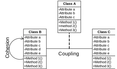
Let us now describe the cohesive class which can per-form a single task within the software procedure. It re-quires little interaction with other procedures that are used in other parts of a program. Cohesion gives the strength to the bond between attributes of a class and it is a concept through which capture the intra-module with cohesion. Therefore, cohesion is used to determine how closely or tightly bound the internal attributes of a class to one another. Cohesion gives an idea to the designer about whether the different attributes of a class belong together in the same class. Thus, the coupling and cohe-sion are related with each other; therefore the Figure 1
shows the general representation of coupling and cohesion.
+Method 1() +Method 2() +Method 3() -Attribute a -Attribute b -Attribute c -Attribute d -Attribute e
Class C
+Method 1() +Method 2() +Method 3() -Attribute a -Attribute b -Attribute c -Attribute d -Attribute e
Class B
+Method 1() +method 2() +Method 3() -Attribute a -Attribute b -Attribute c
Class A
Coupling
C
o
hesi
o
[image:2.595.327.517.85.197.2]n
Figure 1. General representation of cohesion and coupling.
3. UML Class Diagram
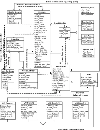
UML class diagram shows the functionality of a system in a diagrammatic form, in which the classes are de-signed and combined for designing the software system. The dependent and independent classes are also designed in the form of classes and subclasses in the UML class diagram. In the current work, authors have taken a UML class diagram of opening the policy for handicapped in Life Insurance Corporation of INDIA as an example to demonstrate the approach. The class diagram shows the complete process of issuing a policy for handicapped. The independent classes and dependent classes are rep-resented in the class diagram; the independent classes are shown along with the solid connecting lines while de-pendent classes are shown alongwith the dotted arrows as shown in the Figure 2.
Independent and Dependent Classes
Independent classes (IC’s) are those classes which are not depending on other classes of the system. So, two classes are independent if one class can function without the presence of other class; these classes are easily solv-able and modifisolv-able separately. However, in any system all the classes are not independent but there are many classes which are dependent to other classes. The func-tionality of dependent classes (DC’s) is affected when the changes are made in the attributes of the classes on which the classes are dependent. Thus, the dependent classes are those classes which use the attributes of other classes, therefore the DC’s are more dependent to other classes if it use number of more attributes of other classes and less dependent if they use less attributes of other classes. The number of classes can be determined by the summation of all the IC’s and DC’s of the system. From the Figure 2,total number of classes (TC’s):
TC = Number of IC’s + Number of DC’s (1)
4. Experimental Study
+Query() +Notifications() +Mobile_No -IEMI_No +service_Provider Mobile_System +Query() +Interact_with_Info() +Deposit_Perm() -Cust_ID +Cust_Name -Plan_Code -Plan_Term -Policy_No -Perm_Term -Sum_Assured -Prem_Amount -Date_of_Commt -Date_of_Birth +Sex -Medical_Status -Disability_Code -Earning -Income P/A -Address -Mobile_No -Prem_Mode -Prem_Due_Date -Date_of_Maturity -Age_at_Maturity -Nominee -Age -Relation Customer +..() -Plan_Code -Plan_Type Plan +Plan_Details() -Plan_Code +Plan_Name Insurance_Plan +Plan _Details() -Plan_Code +Plan _Name Pension_Plan +Plan _Details() -Plan_Code +Plan _Name Unit_Plan +Plan_Details() -Plan _Code +Plan_Name Special_Plan +New_Plans() +Issue _Policies() +Notifications() +Loan() -Zone_Code +Zone_Name -Division _Code +Division _Name +Divisional _Office _Add -Branch_Code +Branch_Office _Add Main_Branch +Issue_Policies () +Deposit_prem () +Loan() -Division _Code -Branch_Code +Zone +Branch_Office _Add LIC_Branch1 +Issue_Policies () +Deposit_prem() +Loan () -Division _Code -Branch_Code +Zone +Branch_Office _Add LIC_Branch2 +Issue_Policies () +Deposit_prem () +Loan() -Division _Code -Branch_Code +Zone +Branch_Office_Add LIC_Branch N-1
+Issue _Policies () +Deposit _prem() +Loan () -Division _Code -Branch_Code +Zone +Branch_Office_Add LIC_Branch N +verify () +Refer () +Reject() -Officer_ID +Officer _Name +Designation +Mobile _No -Address New_Business +Examin () +Confirmation() +Disability _Percentage() -Doctor_ID +Doctor_Name +Designation +Mobile_No -Address Medical_Officer +..() -Cust_Code -Disability_Code -Type_of_Disability -Percentage_of_Disab Disability --- ---+Deposit_Prem() +Acknowledgement () -Branch_Code +Bank_Name +Branch_office _Add Bank * * * * * * * * * * * * * * * * * * * * * 1 1 1 1 1 1 1 Sends confirmation regarding policy Interacts with information
C h ec k s, ve r if y p r op os al s & r e fe r fo r M ed ica l o r re jec t
Select the plan
V eri fy t h e % o f di sa b il it y E x a m ine t h e di sa bi li ty If di sa bi lit y > 6 0 %
[image:3.595.130.469.86.524.2]Auto deduct premium amount Payment Acknowlegement
Figure 2. UML class Diagram for handicapped.
metrics MRC (Message Received Coupling) and DCP (Degree of Coupling) which helps to measure the func-tional strength of the classes of an object-oriented soft-ware system. DCH plays an important role in the field of software designing for measuring the dependency of the classes. The degree of coupling is calculated after calcu-lating the number of DC’s, IC’s and the degree of cou-pling of the system. The metric has been implemented on the designed UML model for life insurance plan for Handicapped persons.
4.1. Degree of Coupling
The degree of coupling [11] is computed as the ratio of number of message received to the number of message
passed. For finding the degree of coupling message re-ceived coupling (MRC) is used, it is a set of number of message received by a class. The degree of coupling is given
MRCDegree of Coupling DC
MPC
(2)
4.1.1. Message Received Coupling (MRC)
The MRC measures the complexity of message received by the classes, as MRC is the number of message re-ceived by a class form the other classes.
4.1.2. Message Passed Coupling (MPC)
among objects of the classes; it is the low level coupling that is achieved through the communication between the components.
For calculating the degree of coupling, the MCG (Mes- sage Calling Graph) is designed and represented below:
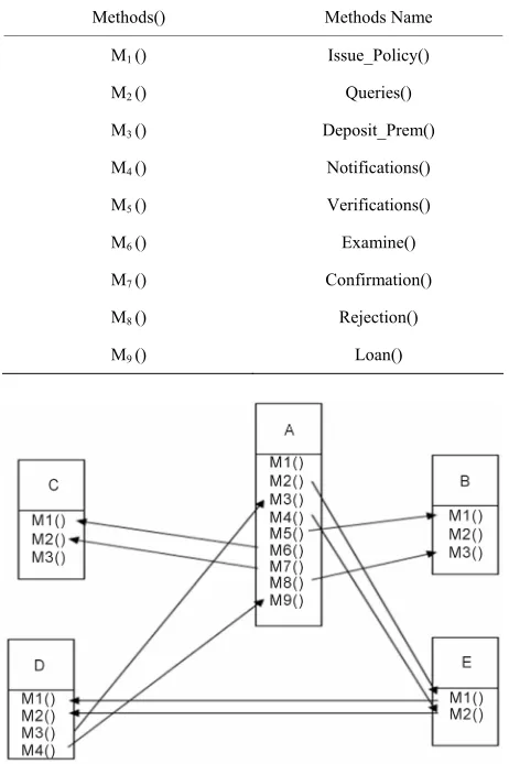
All the nodes of the graph are in the form of A::Mi where Mi is methods of class A, thus A::Mi is called by the B::Mj, C::Mk, D::Ml and E::Mm; where {i, j, k, l, m} = 1, 2, 3, 4, ··· the message calling graph is constructed as follow:
A::Mi
B::Mj
C::Mk
D::Ml
E::Mm
On the basis of above, let us compute the values of MPC, MRC and DC for all the classes which are shown in the Figure 3 and
Methods() Methods Name
M1 () Issue_Policy()
M2 () Queries()
M3 () Deposit_Prem()
M4 () Notifications()
M5 () Verifications()
M6 () Examine()
M7 () Confirmation()
M8 () Rejection()
[image:4.595.57.288.368.715.2]M9 () Loan()
Figure 3. Method calling graph (MCG).
Class A has 9 Methods, but this class has not called any method, thus the MPC for this class is 8 and MRC is 0, therefore the Degree of Coupling can be computed as:
MRCDegree of Coupling DC
MPC
0
DC 0
8
Class B has 3 methods, so the message calling graph for this class is shown below:
B::M1 A::M5
B::M3 A::M8
Thus, the MPC for class B is 0 i.e. the class B has not
sent any statement to other classes and the MRC for class B is 2. Therefore the Degree of Coupling can be calcu-lated as:
2 DC
0
Class C has 3 methods also but no any method passes, so the MCG for class C is as below:
C::M1 A::M6
C::M2 A::M7
Thus, the MPC for class C is 0 i.e. the class C has not
sent any statement to other classes and the MRC for class C is 2. Therefore, the Degree of Coupling can be calcu-lated as:
2 DC
0
Class D has 4 methods, so the MCG for the class E is shown below:
D ::M1 E::M1
D ::M2 E::M2
D ::M3 A::M3
D ::M4 A::M9
sent any statement to other classes and the MRC for class D is 4. Therefore the Degree of Coupling can be calcu-lated as:
4 DC
0
Class E has 2 methods, so the MCG for the class E is shown below:
E::M1 A::M2
E::M2 A::M4
Thus, the MPC for class E is 2 i.e. the class E has
passed two statements to the class D and the MRC for class E is 2. Therefore the Degree of Coupling can be calculated as:
2
DC 1
2
The DC of each class is shown in the tabular form and shown as below (Table 1).
4.2. Degree of Cohesion
In DCH metric the functional strength [12] of the associ-ated attributes within a class is measured which shows that how strongly a method is depending on the attributes of a class. In DCH, the strength of a function is depend-ing on the number of attributes of a class which are used by the function. It is calculated at the attributes level, the ratio of the number of attributes used to the total number of attributes.
NAUDegree of Cohesion DCH
TNA
(3)
where NAU = Number of Attributes Used and TNA = Total Number of Attributes.
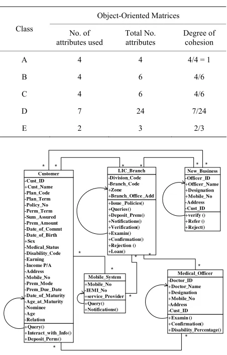
For computing the degree of cohesion, let us design an attribute calling graph (ACG) as shown in Figure 4
which shows the connectivity between the classes and the number of attributes that are used by the methods of a class. The dependent classes are LIC_Branch (Class A), New_Business (Class B), Medical_Officer (Class C), Cuatomer (Class D), and Mobile_System (Class E) from the Figure 2 that helps to design the proposed metric.
According to the attribute calling graph (ACG) the de-gree of cohesion (DCH) for each class is calculated which is shown in the Table 1.
5. Results and Discussions
From the above Table 1 it is shown that the proposed
model is loosely coupled while from the Table 2 it is
Table 1. Class level Metrics.
Object-Oriented Matrices Class
MPC MRC DC
A 8 0 0/8
B 0 2 ∞
C 0 2 ∞
D 0 4 ∞
[image:5.595.101.246.193.248.2]E 2 2 1
Table 2. Attributes level Metrics.
Object-Oriented Matrices
Class No. of
attributes used
Total No. attributes
Degree of cohesion
A 4 4 4/4 = 1
B 4 6 4/6
C 4 6 4/6
D 7 24 7/24
E 2 3 2/3
+Query() +Interact_with_Info () +Deposit_Perm() -Cust_ID +Cust_Name -Plan_Code -Plan_Term -Policy_No -Perm_Term -Sum _Assured -Prem_Amount -Date_of_Commt -Date_of_Birth +Sex -Medical_Status -Disability_Code -Earning -Income P/A -Address -Mobile_No -Prem_Mode -Prem_Due_Date -Date_of_Maturity -Age_at_Maturity -Nominee -Age -Relation
Customer
+verify () +Refer () +Reject() -Officer _ID +Officer_Name +Designation +Mobile_No -Address -Cust_ID
New_Business
+Issue _Policies() +Queries() +Deposit_Prem() +Notifications() +Verification() +Examin() +Confirmation() +Rejection () +Loan() -Division_Code -Branch_Code +Zone +Branch_Office _Add
LIC_Branch
+Examin () +Confirmation() +Disability_Percentage() -Doctor_ID +Doctor_Name +Designation +Mobile_No -Address -Cust_ID
Medical_Officer
+Query() +Notifications() +Mobile_No -IEMI_No +service_Provider
Mobile_System
* * * * * *
*
*
*
*
* *
* *
Figure 4. Attribute calling graph.
shown that the proposed model is highly cohesive due to the maximum number of attributes are used by the methods of the classes.
6. Conclusion
[image:5.595.311.537.244.597.2]maximum numbers of the attributes are used by the numbers of the defined classes. The linking between the classes is demonstrated by the coupling while the strength of class called as attributes is represented by the cohesion. It is observed that the proposed model is highly cohesive although maximum numbers of the attributes are used in the designed UML class model.
7. Acknowledgements
Thanks are due to University Grant Commission New Delhi, for financial support to carry out the above re-search work.
REFERENCES
[1] G. Gui and P. D. Scott, “New Coupling and Cohesion
Metrics for Evaluation of Software Component Reusabil-ity,” Proceedings of the 9th International Conference for
Young Computer Scientists, Zhangjiajie, 18-21 November
2008.
[2] I. Vanderfeesten, H. A. Reijers and W. M. P. van der
Aalst, “Evaluating Workflow Process Designs Using
Co-hesion and Coupling Metrics,” Computers in Industry,
Vol. 59, No. 5, 2008, pp. 420-437. doi:10.1016/j.compind.2007.12.007
[3] T. M. Meyers and D. Binkley, “An Empirical Study of
Slice-Based Cohesion and Coupling Metrics,” ACM Trans-
actions on Software Engineering and Methodology, Vol.
17, No. 1, 2007, Article No. 2.
[4] Y. J. Jeong, H. S. Chae and C. K. Chang, “Semantics
Based Cohesion and Coupling Metrics for Evaluating Understandability of State Diagrams,” IEEE 35th Annual
Computer Software and Applications Conference, IEEE
Computer Society, Washington, 18-22 July 2011.
[5] F. Ensan and W. Du, “A Metric Suite for Evaluating
Co-hesion and Coupling in Modular Ontologies,”
Proceed-ings of the 2010 Conference on Modular Ontologies:
Pro-ceedings of the 4th International Workshop, IOS Press,
Amsterdam, 11 May 2010.
[6] B. Ujhazi, R. Ferenc, D. Poshyvanyk and T. Gyimothy,
“New Conceptual Coupling and Cohesion Metrics for Object-Oriented Systems,” Proceedings of the 2010 10th IEEE Working Conference on Source Code Analysis and
Manipulation, Timişoara, 12-13 September 2010.
doi:10.1109/SCAM.2010.14
[7] S. Husein and A. Oxley, “A Coupling and Cohesion
Met-rics Suite for Object-Oriented Software,” Proceedings of
the 2009 International Conference on Computer
Tech-nology and Development, Vol. 1, IEEE Computer Society,
Washington, 2009. doi:10.1109/ICCTD.2009.209
[8] I. Chowdhury and M. Zulkernine, “Can Complexity,
Cou-pling, and Cohesion Metrics Be Used as Early Indicators
of Vulnerabilities?” Proceedings of the 2010 ACM
Sym-posium on Applied Computing, ACM, New York, 2010,
pp. 1963-1969.
[9] I. Chowdhury and M. Zulkernine, “Using Complexity,
Coupling, and Cohesion Metrics as Early Indicators of Vulnerabilities,” Journal of Systems Architecture, Vol. 57, No. 3, 2011, pp. 294-313.
doi:10.1016/j.sysarc.2010.06.003
[10] S. Oh, H. Y. Yeom and J. Ahn, “Cohesion and Coupling
Metrics for Ontology Modules,” Information Technology
and Management, Vol. 12, No. 2, 2011, pp. 81-96.
doi:10.1007/s10799-011-0094-5
[11] P. Gandhi and P. K. Bhatia, “Optimization of Object-
Oriented Design Using Coupling Metrics,” International
Journal of Computer Applications, Vol. 27, No. 10, 2011,
pp. 41-44.
[12] H. Li, Y. He, Z. H. Jiang, Y. C. Huang and Q. Huang,
“High-Cohesion and Low-Coupling Integrative Joint for
Space Manipulator,” Advanced Intelligent Mechatronics,
IEEE/ASME International Conference, Singapore City,