Random Linear Network Coding for
Satellite-Aided Flight Data Streaming
Ioannis Chatzigeorgiou and Catherine Price
School of Computing and Communications, Lancaster University Lancaster LA1 4WA, United Kingdom
Email:{i.chatzigeorgiou, c.price}@lancaster.ac.uk
Abstract—In response to the recommendation by the International Civil Aviation Organization for the enhance-ment of flight tracking, Inmarsat developed a platform that allows flight data recorder information to be streamed off aircrafts to defined recipients via its geostationary satellites. This paper considers various data forwarding mechanisms and demonstrates that random linear network coding can support reliable transmission that is more resilient to channel errors. Resilience can be further improved if partial packet recovery is enabled and if authorized users with receive-only capabilities share retrieved data with aviation safety recipients.
I. INTRODUCTION
Flight Data Recorders (FDRs), commonly known as black boxes, are fitted to commercial aircraft to record a range of parameters during a flight. In the event of an accident, the recorded information is recovered and analyzed in an effort to diagnose the cause of the accident. Problems emerge when the recorded data has been corrupted (e.g., flight RQ904) or the FDR cannot be retrieved because the wreckage of an aircraft cannot be reached or cannot be located (e.g., flight MH370).
Since the MH370 incident in 2014, proposals for live streaming flight data via geostationary satellites started to emerge [1]. The International Civil Aviation Organi-zation (ICAO) proposed the concept of the Global Aero-nautical Distress and Safety System (GADSS) to ad-dress requirements for global flight tracking, autonomous distress tracking and flight data recovery. According to ICAO, airlines are required to regularly transmit highly accurate position information from November 2018 and additional flight data from January 2021 [2]. Inmarsat, in collaboration with Cobham, Thales and Honeywell, developed the SwiftBroadband-Safety (SB-S) communi-cation platform [3] as a means to support all GADSS requirements. The Transmission Control Protocol (TCP) has been adopted by SwiftBroadband services for data transmission [4]. In late 2017, the SB-S platform entered service evaluation on a commercial aircraft [5].
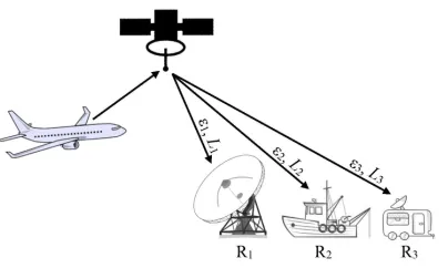
[image:1.612.329.531.198.319.2]This paper considers TCP-like transmission, referred to as uncoded transmission, of flight data from a satellite to a main station, e.g., an aviation safety recipient, and investigates other forwarding schemes that can improve the resilience of the system. The motivation for this paper
Fig. 1. Example of a system, in which a satellite relays flight data to three receivers over channels characterized by different packet erasure probabilities (ε1,ε2,ε3) and average burst lengths (L1,L2,L3).
is to gauge the benefits of index coding [6] and random linear network coding [7], without or with partial packet recovery [8], when main stations collaborate either with each other or with auxiliary stations, e.g., users that have been authorized to receive flight data.
The paper has been structured as follows: Section II presents the system model, the channel model and the considered system configurations. Section III describes the schemes under investigation that can be used by a satellite to relay flight information. Performance results are discussed in Section IV and key findings are sum-marized in Section V.
II. SYSTEMMODEL
transmitted packets over the two stages, whereN ≥K. Given that each additional packet in the retransmission stage requires energy from the satellite and introduces delay to the recovery of the flight data, achieving a value ofN as close as possible toK will ensure thatK data packets’ worth of information will be delivered at the lowest energy and delay cost.
The Gilbert channel [9] has been used in this paper to model packet losses, also referred to aspacket erasures, between the satellite and a receiver. This simple model can capture the bursty nature of the satellite channel, i.e., the occurrence of consecutive packet erasures, and is often used in the literature when satellite communication schemes are assessed, e.g., [10] and [11]. The Gilbert channel is a two-state Markov chain, according to which packets are correctly received during a ‘good’ state but are erased during a ‘bad’ state. Transitions between the two states occur with probabilitiespgb,pgg,pbgandpbb, where pgg = 1−pgb and pbb = 1−pbg, as depicted in Fig. 2. The steady-state probability of being in the ‘bad’ state represents the packet erasure probability and is given by ε = pgb/(pgb +pbg) [11], [12]. The expected number of consecutive packet erasures provides the average length of an erasure burst, and is equal to
L = 1/pbg [11]. In this paper, parameters ε and L are taken to be given quantities. For this reason, the transition probabilities have been expressed in terms of
εandL, i.e.,pbg = 1/Landpgb=ε/[L(1−ε)]. Index
i has been appended to ε and L as a reference to the packet erasure probability and the average burst length, respectively, of the link between the satellite and receiver Ri, as shown in Fig. 1.
The following three configurations have been consid-ered, based on the type and connectivity of the receivers:
• Independent main stations: Each main station trans-mits feedback messages to the satellite in an effort to collect sufficient packets and recover the flight data. • Connected main stations: The main stations act
independently during both stages. If the packets trans-mitted by the satellite reach the maximum allowable value and one or more stations have not recovered the flight data, the stations use a reliable backbone network to exchange packets in real time or offline. • Main station connected to auxiliary stations: A
sin-gle main station requests packets through a feedback channel in the retransmission stage, while auxiliary stations are in receiving mode in both stages. If the main station is not successful in recovering the flight data by the end of the retransmission stage, it uses reliable terrestrial links to collect any missing packets from auxiliary stations in real time or offline. This section provided details about the system setup, the channel model and the underlying assumptions. The candidate schemes for forwarding packets in the retrans-mission stage are discussed in the following section.
g
b
pgb
pbg
[image:2.612.318.538.236.278.2]pbb pgg
Fig. 2. The Gilbert channel model, wheregandbrepresent the ‘good’ state and the ‘bad’ state, respectively.
III. FORWARDINGSCHEMES
Let U= [u1 . . .uK]T be a matrix composed of K
packets of flight data that have been successfully re-ceived by the satellite. The packets that will be transmit-ted by the satellite during the two stages can be expressed as follows:
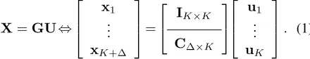
X=GU⇔
x1
.. .
xK+∆
=
IK×K
C∆×K
u1
.. .
uK
. (1)
MatrixGis the vertical concatenation of theK×K
iden-tity matrixIK×K and the∆×K matrixC∆×K, where
∆≤N −K. Note thatIK×K represents the broadcast
stage and C∆×K characterizes the forwarding scheme
that is used in the retransmission stage. The column vectorxcontains the transmitted packetsx1, . . . ,xK+∆.
At the end of the two-stage process, receiverRi will construct matrixDi from the rows ofGthat are
asso-ciated to successfully received packets. The number of rows that sub-matricesIN×N andC∆×Kwill contribute
toDidepends on the link conditions, which are captured
by the packet erasure probabilityεiand the average burst lengthLi. Receiver Ri will recover u1, . . . ,uK if and
only if Di contains K linearly independent rows or,
equivalently, the rank ofDi is K, i.e., rk(Di) =K.
The structure of matrixC∆×K as well as the value of
∆ are determined by the adopted transmission scheme and the content of the feedback that is sent by the main stations, as explained in the remainder of this section.
A. Uncoded Transmission (UT)
In the context of this paper, uncoded transmission
implies that data packets are not linearly combined at layers higher than the physical layer. We assume that the effect of forward error correction at the physical layer can be encapsulated in the packet erasure probability and the average burst length of the ‘extended channel’ that is composed of the channel encoder at the satellite, the wireless channel and the channel decoder at a receiver.
In uncoded transmission, each main station reports to the satellite the indices of the data packets that have not been delivered successfully during the broadcast stage. The satellite collects the feedback messages and retransmits the union of all requested data packets during the retransmission stage. For example, if data packetuk
is retransmitted at time step δ, then row δ of matrix
entries of rowδ will be set to zero, where1≤k≤K
and1≤δ≤∆. This process is repeated until all main stations recover the K data packets (∆ < N −K) or the satellite transmits the maximum allowable number of packets (∆ =N−K).
Example 1. Let u1, . . . ,u4 be the data packets trans-mitted by the satellite to two main stations,R1andR2,
during the broadcast stage. Assume thatR1requests the
retransmission of u2, while R2 needs u1 and u4. The
satellite sends x5 =u1, x6 =u2 andx7 =u4. If x5
is not received byR2, the satellite sendsx8 =u1. The
retransmission stage can thus be summarized by
C4×4=
1 0 0 0 0 1 0 0 0 0 0 1 1 0 0 0
.
B. Index Coding (IC)
At the end of the broadcast stage, main stations send feedback messages to the satellite to request missing data packets, as in uncoded transmission. Whenindex coding
[6] is employed, the satellite uses the feedback messages to build a ‘received’ set and a ‘requested’ set for each
main station; the former set contains data packets that have been successfully delivered to the main station and the latter set consists of data packets that are needed by the main station. Given that all main stations aim to recover the flight data, the union of the ‘received’ and ‘requested’ sets of each main station contains all of the
Kdata packets. The encoding process takes into account the sets of all main stations to identify data packets that will be added and generate coded packets. Operations on data packets are over the finite fieldF2, that is, addition is
equivalent to the bit-by-bitXORoperation. Main stations can perform XOR between received coded packets and data packets in their ‘received’ sets in order to derive data packets that are members of the ‘requested’ sets. The objective of index coding is to generate and transmit the minimumnumber of coded packets that will enable all main stations to derive their requested data packets.
The Least Difference Greedy (LDG) clique-cover al-gorithm, which was proposed in [6] for the construction of coded packets, has been adapted to the system model that is considered in this paper. Coded packets are retransmitted if they are needed but not received by one or more main stations, as long as the maximum allowable number of packet transmissions is not exceeded.
Example 2. As in Example 1, R1 andR2 request data
packetsu2 and{u1,u4}, respectively. Index coding at the satellite generatesx5=u1+u2andx6=u4. Ifx5is not delivered toR2, the satellite resendsx7=u1+u2.
Recall thatR1 received u1 in the broadcast stage and
can performXORbetweenx5 andu1 to deriveu2, i.e.,
u1+x5=u2. Similarly,R2 obtainsu2+x7=u1. The
retransmission stage is described by
C3×4=
1 1 0 0 0 0 0 1 1 1 0 0
.
C. Random Linear Network Coding (RLNC)
Let M be the set of indices of receivers that are main stations not in possession of all of the K data packets. Also, let |M| ≤S be the cardinality of M. When random linear network coding (RLNC) [7] is used, main stations report to the satellite the number – but not the indices – of data packets that they have collected. This is equivalent to reporting the rank of each matrix
Dm form∈ M. The satellite determines and transmits
the maximum number of required coded packets based onK−min{rk(D1), . . . ,rk(D|M|)}. Coded packets are
random linear combinations of data packets. In other words, the elements of C∆×K are selected uniformly
at random from Fq, where q is a prime power. For a fair comparison between RLNC and index coding, the encoding operations are performed overF2in this paper.
After the coded packets have been transmitted, main stations update their matricesD1, . . . ,D|M|, recalculate
their ranks and inform the satellite. Additional coded packets are randomly generated and transmitted until all main stations recover the flight data or the maximum allowable number of packet transmissions is reached.
Example 3. Similarly to the previous examples,R1 and
R2 have collected {u1,u3,u4} and {u2,u3},
respec-tively, hencerk(D1) = 3andrk(D2) = 2. The satellite randomly generates and transmits two coded packets, for examplex5 =u1+u2+u3 andx6 =u2+u4. If both stations receive any of the two coded packets, then
rk(D1) = 4andrk(D2) = 3. The satellite subsequently transmits one more randomly generated coded packet, for example x7 =u1+u4. The matrix that describes the retransmission stage can be expressed as
C3×4=
1 1 1 0 0 1 0 1 1 0 0 1
.
D. RLNC with Partial Packet Recovery (RLNC-PPR)
LetSi be the set of packets that have been correctly recovered by the physical layer of receiver Ri and forwarded to higher layers. On the other hand, let setFi consist of packets that contain irrecoverable bit errors. Based on those definitions, |Si|+|Fi| =K+ ∆. The size of Fi is proportional to the channel parameters
εi and Li. If matrix X contains the K + ∆ packets transmitted by the satellite, as shown in (1), letYibe the
matrix composed of the packets inSi∪ Fias rows. The relationship Yi =X+Ei holds, where Ei is referred
to as the error matrix. Nonzero elements ofEi identify
In RLNC, the packets inFi are discarded. MatrixDi is built from the rows of G in (1) that are associated
to the packets in Si. In essence, the packets in Si and matrix Di compose a linear system of equations over F2 that can be solved ifK of the equations are linearly
independent, i.e.,rk(Di) =K, as previously explained.
RLNC with partial packet recovery (RLNC-PPR) [8] uses principles of compressive sensing to repair and utilize some of the packets inFi. According to RLNC-PPR, receivers have knowledge of matrixG. This can be
achieved if each row of C∆×K is created by a
pseudo-random number generator. Knowledge of the generator’s seed and the index of a packet, whether the packet has been received in error or not, can be used by a receiver to reconstruct the corresponding row ofC∆×K. Appending C∆×KtoIK×K producesG. Based onG, a new matrix H can be designed, such that HG=0. IfSi does not
holdK linearly independent packets, receiverRi builds matrixYifrom the packets inSi∪ Fi. Multiplication of H byYi gives:
HYi=A⇔H X+Ei
=A
⇔H GU+Ei=A
⇔HEi=A. (2)
Matrices H and Yi are available to receiver Ri, and
matrixAcan be obtained from the productHYi. Thus,
the objective of Ri is to determine the best estimate of
Ei, denoted by Eˆi, that satisfies equation (2). This is
a common problem in compressive sensing that can be solved by conventional techniques, such as per-column
basic pursuit [8], [13]. Adding Eˆi to Yi produces an
estimate of X, that is, Xˆ =Yi+Eˆi. Rows of Xˆ that
correspond to successfully repaired packets are added to setSi, matrixDi is updated and its rank is recalculated.
If the rank ofDi is still less thanK, additional packet
transmissions are requested, as in RLNC.
IV. RESULTS ANDDISCUSSION
The four forwarding schemes (UT, IC, RLNC and RLNC-PPR) in the three system configurations under investigation (independent main stations, connected main stations and a single main station connected to auxiliary stations) are compared in this section. Their performance has been measured in terms of the number of packets that need to be transmitted by the satellite, under certain channel conditions, for all main stations to decode the flight data with a target probability. For instance, if Z
is a random variable that gives the number of packets transmitted by the satellite, then the cumulative distribu-tion funcdistribu-tionP(Z≤K+ ∆)represents the probability that all main stations will decode the K data packets afterK+ ∆packet transmissions. Henceforth, we shall refer toP(Z≤K+ ∆)as the decoding probability.
Simulations considered systems with S receivers, for
S ∈ {1,2,3}. In all system configurations, receiverR1
0 0.1 0.2 0.3 0.4 0.5 0.6 0.7 40
[image:4.612.314.537.57.214.2]60 80 100 120 140 160 180 200 220 240
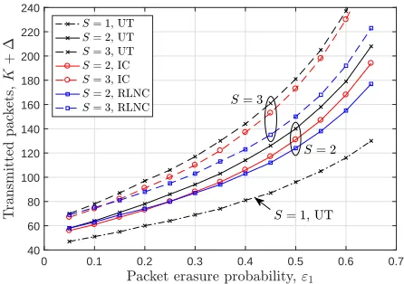
Fig. 3. Number of packets required to be transmitted by the satellite to Sindependent main stations, forS= 1,2,3, over channels of different erasure probabilities to achieve a decoding probability of95%.
is a main station. The packet erasure probability of the channel between the satellite and receiverR1was varied
in the range ε1 ∈ [0.05. . .0.65]. The average length of erasure bursts was set equal to L1= 2 packets. The remaining receivers were assumed to experience worse channel conditions thanR1. The channel parameters for
Riare given byεi=εi−1+0.05andLi=Li−1+ 2, for
1< i≤S. Flight information was divided into blocks, each consisting ofK= 40data packets. The length of a data packet was taken to be128bits. The LDG algorithm for IC was implemented in MATLAB. The compressive sensing problem in (2) for RLNC-PPR was solved using the basic pursuit algorithm of SparseLab [14].
Simulation results determined the number of packets that need to be transmitted by the satellite, on average, to enable all main stations to decode all data packets with probability95%for different values ofε1. Fig. 3 shows the impact of increasing the number of independent main stations on packet transmissions. Additional main sta-tions provide redundancy and allow parallel processing of recovered flight data at the cost of a higher number of packet transmissions. ForS >1, UT is the least efficient scheme for any value ofε1. IC offers a negligible gain at very low packet erasure probabilities but its performance converges to that of UT as the value ofε1increases. For a fixed number of transmitted packets and medium to high values ofε1, RLNC can support a decoding probability of95%at worse channel conditions than UT and IC.
0 0.1 0.2 0.3 0.4 0.5 0.6 0.7 40
[image:5.612.314.537.57.214.2]60 80 100 120 140 160
Fig. 4. Number of packets required to be transmitted by the satellite to Sconnected main stations, forS= 1,2,3, over channels of different erasure probabilities to achieve a decoding probability of95%.
each packet by at least one main station is more likely. Hence, the union of all packets received by all main stations can lead to the recovery of the flight data with a higher probability. In contrast to IC, which transmits copies of undelivered coded packets, RLNC transmits different randomly-generated coded packets. As a result, linear independence between packets in the union of all received packets is more probable, and the likelihood of recovering the flight data is higher than in IC.
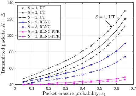
Fig. 5 shows the performance gain from having mul-tiple receivers but only one main station among them. In all cases, an increase in the number of auxiliary stations improves the overall performance. The notable advantage of combining PPR with RLNC is also illustrated. For example, assume that S = 3 andε1 = 0.6. As seen in Fig. 5, RLNC cannot guarantee a decoding probability of 95%if fewer than67packets are transmitted. If RLNC decoding fails to recover the flight data, RLNC-PPR decoding can be performed on the same received packets and attain a decoding probability of95%, provided that at least 44 packets have been broadcast. Therefore, the main station could perform RLNC decoding in real time and RLNC-PPR decoding offline in order to increase the amount of recovered flight data.
V. CONCLUSIONS
This paper considered a satellite that stores and trans-mits vital flight information to authorized recipients over independent links that have been modeled as Gilbert channels. The transmission of packets containing flight data is a two-stage process; the broadcast stage is followed by the retransmission stage. The latter stage is controlled by feedback messages sent by recipients to the satellite. Packet transmissions can be reduced or resilience to packet erasures can be strengthened if (i) the satellite uses RLNC in the retransmission stage to encode data packets, and (ii) multiple recipients collect coded packets, provided that only one of them sends feedback
0 0.1 0.2 0.3 0.4 0.5 0.6 0.7 40
[image:5.612.76.297.57.214.2]60 80 100 120 140
Fig. 5. Number of packets required to be transmitted by the satellite to a single main station and(S−1)auxiliary stations, forS= 1,2,3,
in order to achieve a decoding probability of95%.
during the retransmission stage and gathers packets from other recipients at the end of the two-stage process. If RLNC decoding cannot fully reconstruct the flight data due to poor channel conditions or a short retransmission stage, PPR can be included in the RLNC decoder to significantly enhance its decoding capability.
REFERENCES
[1] Y. Yu, “The aftermath of the missing flight MH370: What can engineers do?” Proc. IEEE, vol. 103, no. 11, pp. 1948–1951, Nov. 2015.
[2] “Annex 6: Operation of aircraft,” International Civil Aviation Organization, 2016, Amendments 39 and 40.
[3] “SwiftBroadband-safety: The future of aircraft communications,” Inmarsat, Nov. 2016.
[4] “SwiftBroadband and IP data connections,” Inmarsat, Jan. 2008. [5] “Inmarsat SB-Safety connected flight deck enters service evaluation on United Airlines,” Inmarsat Press Release, Nov. 2017. [Online]. Available: http://bit.ly/2FUqYXJ
[6] Y. Birk and T. Kol, “Coding on demand by an informed source (ISCOD) for efficient broadcast of different supplemental data to caching clients,”IEEE Trans. Inf. Theory, vol. 52, no. 6, pp. 2825–2830, Jun. 2006.
[7] T. Ho, M. M´edard, R. Koetter, D. R. Karger, M. Effros, J. Shi, and B. Leong, “A random linear network coding approach to multicast,”IEEE Trans. Inf. Theory, vol. 52, no. 10, pp. 4413– 4430, Oct. 2006.
[8] M. S. Mohammadi, Q. Zhang, and E. Dutkiewicz, “Reading damaged scripts: Partial packet recovery based on compressive sensing for efficient random linear coded transmission,” IEEE Trans. Commun., vol. 64, no. 8, pp. 3296–3310, Aug. 2016. [9] E. N. Gilbert, “Capacity of a burst-noise channel,”Bell Syst. Tech.
J., vol. 39, no. 5, pp. 1253–1266, Sep. 1960.
[10] R. Alegre-Godoy and M. A. V´azquez-Castro, “Spatial diversity with network coding for ON/OFF satellite channels,” IEEE Commun. Lett., vol. 17, no. 8, pp. 1612–1615, Aug. 2013. [11] J. Cloud and M. M´edard, “Network coding over SATCOM:
Lessons learned,” in Proc. Int. Conf. on Wireless and Satellite Systems (WiSATS), Bradford, UK, Jul. 2015, pp. 272–285. [12] T. Rancurel, D. Roviras, and F. Castani´e, “Expression of the
capacity for the Gilbert channel in presence of interleaving,” in
Proc. IEEE Int. Conf. on Acoustics, Speech and Signal Processing (ICASSP), Salt Lake City, USA, May 2001, pp. 2533–2536. [13] D. L. Donoho, “Compressed sensing,”IEEE Trans. Inf. Theory,
vol. 52, no. 4, pp. 1289–1306, Apr. 2006.