© 2019, IRJET | Impact Factor value: 7.211 | ISO 9001:2008 Certified Journal
| Page 1
The Study of Damage Level of Tandem Breakwater
Nur Aini Mohd Arish
1, Othman A. Karim
2, Wan Hanna Melini Wan Mohtar
3[1]
Lecturer, Department of Civil Engineering Technology, Faculty of Engineering Technology,
Universiti Tun Hussein Onn Malaysia,
[2]
Proffesor
[3]Senior
Lecturer, Department of Civil and Structural Engineering,
Faculty of Engineering and Built Environment, Universiti Kebangsaan Malaysia
---***---Abstract -
In this paper, the performance of tandembreakwater was investigated. Tandem breakwater is a sheltered breakwater consisting of a conventional rubble mound breakwater with a seaward-submerged breakwater. Tests are performed in a wave basin with dimensions of 25 m length, 18 m width and 1.2 m height. Regular waves were generated from a piston type multi element wave maker with wave height, H = 0.15, 0.18 and 0.20 m and wave period, T= 2.05, 2.20 and 2.50 sec.Tests are carried out for different spacing between two rubble mound structures (X/d = 6.67-8.89(4 m) and X/d=10.0-13.33 (6 m)) and for different relative heights (h/d=0.42-0.56). Every test was conducted up to1000 waves to measure the level of the damage, S for quarry rock and cube armour layer. It is observed that a submerged breakwater constructed at a seaward distance at X/d = 10.0-13.33 (6 m), the maximum damage level, S is reduced for about 39.4% (quarry rock) and 35.7% (cube) compared with X/d = 6.67-8.89 (4 m). As the degree of wave angle is increasing, the damages for both armour layers are decreasing with the highest damage is for 0° of wave attack.
Key Words: Tandem breakwater, Damage level, Submerged breakwater, Wave attack
1. INTRODUCTION
Breakwaters are coastal structures, which are widely used for providing shelter from the wave action. It have been built all over the times but their structural development and design procedure is still under immense and continuous change. Breakwaters play a significant role in dissipating wave energy and protecting shorelines from erosion[1], [2]. Low crested and submerged structures such as detached breakwaters and artificial reefs are becoming very popular coastal protection precautions.The submerged breakwaters are used for protecting an already existing breakwater. It can be used as a rehabilitation structure for a damaged breakwater, which is secured from storm waves [3]. Each type of breakwater will have different hydrodynamic performances due to the variation of wave dissipation, reflection and transmission in response to the structure geometry.[4]
The conventional rubble-mound breakwater consists of a core of finer material covered by big blocks, which is called as an armour layer. The armour layers are important as to prevent the finer material of a breakwater from eroding and
washed away and to minimum the wave attack. It is also to protect the inner layer of the breakwater [5]. The principal function of a conventional rubble mound breakwater is to protect a coastal area from excessive wave action but sometimes it cannot withstand the extreme waves. The possible way to minimize this phenomenon is to reduce the effect of incident wave energy on the breakwater system by arranging a submerged breakwater in front of it. The study on the stability of breakwater armour layers has been done widely which concentrate on the stability of armour layer on a slope. Hudson [6] was one of the earliest researcher that made a formula to define the stability of rocks on a slope of the armour layer.
2. LITERATURE REVIEW
[image:1.595.323.548.501.640.2]There are many types of failure modes of rubble mound breakwaters, some of common are loss or damage of armour units, movement of armour layer, cap movement and others as in Figure 1. The loose of stability of a slope involving two types of stages, which are damage and failure. The damage can be defined as the amount of displacement of the rocks per unit of width [7].
Fig -1: Failure modes of rubble mound breakwaters[8]
There are two methods of measuring the damage level, S
© 2019, IRJET | Impact Factor value: 7.211 | ISO 9001:2008 Certified Journal
| Page 2
where A is the average of eroded cross-sectional area of thearmour layer and Dn50is nominal diameter of armour stones.
Vidal [11] took in consideration for both methods and proposed the formula as
where N is the number of displaced armour units , n is the porosity of the armour layer, and X is the length of the trunk section of the breakwater.
Mostly the research of tandem breakwater are carried out in flumes. This study will focus on the damage level, S for the tandem breakwater system when exposed to various wave attack at different water depth and different breakwater spacing.
3. MATERIALS AND METHODS
The wave basin in the National Hydraulic Research Institute of Malaysia (NAHRIM) is used for the experimental study. Experiments were performed in a wave basin of dimensions 25 m long, 18 m wide and 1.2 m deep. The experimental setup includes the wave paddle, wave absorber and the tested models, which are the conventional rubble mound breakwater and the submerged breakwater models) as shown in Figure 3. The conventional non-overtopping rubble mound breakwater is constructed with height of 60 cm and uniform slope of 1V to 2H with a scale of 1: 20. Laboratory model of rubble mound breakwater is scaled according to Froude’s Law. All tests were performed with regular waves of various height and period. Table 1-3 gives the characteristic values for the conventional and submerged breakwater used in the tandem breakwater system. Table 4 shows the wave and submerged parameter in non-dimensional quantities.
[image:2.595.332.530.176.336.2]Fig -2
:
Wave basin with tandem breakwater systemTable -1: Wave characteristics
Characteristics Value
Wave height, H 0.15m, 0.18 m and 0.20 m
Wave period, T 2.05s, 2.20s and 2.50s
Number of
waves, N 1000 waves
Angle of wave
attack, θ 0°, 15°, 30° dan 60°
Water depth, d 0.45 m, 0.50 m and 0.60 m
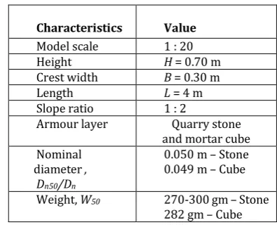
Table -2: Characteristics for conventional breakwater model
Characteristics Value
Model scale 1 : 20
Height H = 0.70 m
Crest width B = 0.30 m
Length L = 4 m
Slope ratio 1 : 2
Armour layer Quarry stone
and mortar cube Nominal
diameter , Dn50/Dn
0.050 m – Stone 0.049 m – Cube
Weight, W50 270-300 gm – Stone
[image:2.595.332.535.377.576.2]282 gm – Cube
Table -3:Characteristics for submerged breakwater model
Characteristics Value
Model scale 1 : 20
Height h = 0.25 m
Crest width B = 0.30 m
Length L = 4 m
Side slope 1 : 2
Material Quarry stones
Nominal diameter, Dn50
0.03 m
Weight, W50 150-200 gm
Porosity 0.45
Distance between conventional breakwater and submerged breakwater, X
[image:2.595.46.291.569.644.2]4.0 m and 6.0 m
Table -4: Dimensionless parameter for wave and submerged breakwater
Characteristics Value
Relative height, h/d
Relative width, B/d 0.42-0.56 0.5-0.67 Relative submergence,
F/Hi 1.00-2.33
Relative distance, X/d Wave steepness, H/gT2
8.33-15.56 0.0024-0.0044
Relative depth, d/gT2 0.0073-0.015
[image:2.595.332.531.616.721.2]© 2019, IRJET | Impact Factor value: 7.211 | ISO 9001:2008 Certified Journal
| Page 3
arrangement of tandem breakwater for 60° of wave attack.During the experiment, the movement of armour unit and damage of the main breakwater were observed. The damage of the structures was measured by counting the number of stones displaced from its original position after every run of 1000 waves. Two types of armour has been applied, quarry rock and cube armour. Coloured armour unit (Figure 3) is to make the process of counting the displaced armour units much easier and practical.
Fig -3
:
Coloured armour unitsFig -4
:
Tandem breakwater system4. RESULTS AND DISCUSSION
a) Effect of steepness parameter (H/gT2) on damage level
(S)
Fig -5
:
Breakwater spacingX/d = 4m (0 degree), water depth 0.45 mFigure 5 is a graph of damage level, S versus wave steepness,
H/gT2 for quarry stone and cube armour layer. This is as
steeper waves have greater energy resulting more damage to the breakwater. The damage also increases with a decreasing wave period. This is because short period waves disturb the displaced stones within a smaller time interval without allowing them to settle. The damages due to shorter period waves of 2.05 sec (higher values of H/gT2) are seen
on right hand side of the Figure 4 whereas, damage of longer period waves of 2.50 sec (smaller values of H/gT2) are on the
left hand side. The damage level, S for quarry stone is higher than cube armour layer. Interlocking is better for cube compared to quarry stone. Concrete cubes armours were in general more stable than rock armours [12].
[image:3.595.68.258.210.481.2]b) Effect of steepness parameter (H/gT2) on damage level(S)
Figure 6 represents the results for damage level, S with the effect of various relative depth, d/gT2. The results is for the
condition of 0 degree angle of wave attack and breakwater spacing, X/d = 4 m for amour quarry rock. It shows that the damage increases with an increase in depth of water. This is because with larger depths higher waves will sustain without much breaking. Considering all the ranges of d/gT2
(0.00734-0.01092(0.45m), 0.00816-0.01213(0.50m)
0.00979-0.01455(0.60 m)), the increase in damage levels are 4.38 to 4.88 (11.4%), 4.81 to 5.55 (15.4%) and 7.51 to 8.59 (14.4%) respectively, for the shortest wave of period of 2.05 sec.
Fig -6
:
Variation of Damage level, S with various relative depth, d/gT2 (4 m spacing, 0 degree) [image:3.595.314.555.430.580.2]c) Effect of relative distance, X/d on damage level (S)
[image:3.595.45.278.545.723.2]© 2019, IRJET | Impact Factor value: 7.211 | ISO 9001:2008 Certified Journal
| Page 4
Fig -7
:
Damage level, S for quarry rock armour withX/d =6.67-8.89(4m), X/d = 10.0-13.3 (6m) and various relative depth, d/gT2
[image:4.595.280.562.53.200.2]Comparison of damage level, S for quarry rock armour in terms of percentage is represented in Table 5. Initially at X/d = 6.67-8.89 (4 m) for 0.45 depth, the damage level, S is 4.89 and reduced to 2.96 for X/d = 10.0-13.33(6 m) at the same depth. This gives the percentage of difference about 39.4%.
Table -5: Damage level, S comparison for quarry rock armour.
d/gT2
Damage level, S
Percentage of difference X/d =
6.67-8.89
X/d = 10.0-13.33
0.00734-0.01092 (0.45m) 0.00816-0.01213
(0.50m) 0.00979-0.01455
(0.60m)
4.89 5.56 8.59
2.96 5.41 8.37
39.4 2.67 2.60
For cube armour, the same graph is plotted to show the pattern of damage level, S for X/d = 6.67-8.89(4m) and X/d =
10.0-13.3. It is clearly shows that with increase in breakwater spacing (X/d), the damage level, S decreases. Table 6 tabulated the damage level, S for every water depth for both
X/d. The highest percentage of difference is at 0.45 m water depth for X/d = 10.0-13.3 (6 m) which is 35.7%.
Fig -8
:
Damage level, S for cube armour withX/d = 6.67-8.89(4m), X/d = 10.0-13.3 (6m) and various relative depth,d/gT2
d/gT2
Damage level, S
Percentage of difference X/d =
6.67-8.89 X/d =13.33
10.0-0.00734-0.01092 (0.45m) 0.00816-0.01213
(0.50m) 0.00979-0.01455
(0.60m)
3.15 3.83 5.48
2.03 3.38 4.43
35.7 11.8 19.2
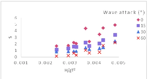
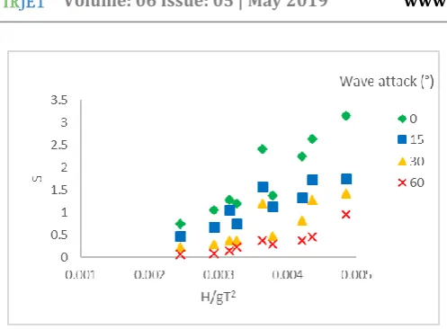
d) Influence of angle of wave attack on damage level (S)
The comparison was made using quarry rock armour and cube armour layer with various angle of wave attack (θ) as shown in Figure 9 and 10. From both graphs, the highest damage is for 0° of wave attack. As the degree of wave angle is increasing, it can be seen that the damages for both armour layer is decreasing. As the wave angle is increasing, the wave attack is oblique to the breakwater. This will cause the reduction of wave height because of the refraction process hence the armour layer will be in the effective angle. Obliquely wave attack will reduce the damage compared with wave attack that is perpendicular to breakwater ([13], [14][15].
Also from Figure 9, for quarry rock armour layer with time period 2.05 s and relative depth, d/gT2 0.00734-0.01092
(0.45m), the maximum damage level (S) decreasing from 4.89(0°) to 3.41(15°) which is 30.3%, from 3.41(15°) to 2.44(30°) or 28.3% and from 2.44(30°) to 2.22(60°) or 9.1%. As for cube armour layer the maximum damage level decreasing from 3.41(0°) to 1.75(15°) or (44.4%), from 1.75(15°) to 1.43(30°) or 18.6% and from 1.43(30°) to 0.95(60°) or 33.3%. Cube armour layer are more stable, less damage compared to stone because of the surface, and structure is more homogenous.
Fig -9
:
Damage level (S) for tandem breakwater using quarry rock armour layer with various angles of wave [image:4.595.35.289.378.488.2] [image:4.595.314.556.523.651.2] [image:4.595.37.289.583.709.2]© 2019, IRJET | Impact Factor value: 7.211 | ISO 9001:2008 Certified Journal
| Page 5
Fig -10: Damage level (S) for tandem breakwater using cube armour layer with various angles of wave attack
CONCLUSION
The submerged breakwater successfully trips the steeper waves and dissipates wave energy, hence protecting the main breakwater. As the distance between breakwater (X/d) increases, the waves that break over the submerged breakwater, loose some more energy while propagating in the energy dissipation zone. Relative distance at X/d = 10.0-13.33(6 m), the maximum damage level, S is reduced for about 39.4% (quarry rock) and 35.7% (cube) compared with
X/d = 6.67-8.89 (4 m). Increasing degree of wave attack reduces the damage compared with wave attack that is perpendicular to breakwater. The results shown for both quarry rock and cube armour.
ACKNOWLEDGEMENT
The authors are appreciative to the National Hydraulic Research Institute of Malaysia (NAHRIM) for the facilities provided for the study and permission granted to publish the results.
REFERENCES
[1]K. G. Shirlal, S. Rao, V. Ganesh, and Manu, “Stability of breakwater defenced by a seaward submerged reef,” Ocean Eng., vol. 33, no. 5–6, pp. 829–846, 2006.
[2]K. Rajendra, R. Balaji, and Mukul, “Review of Indian research on innovative breakwaters,” Indian J. Geo Mar. Sci., vol. 46, no. 03, pp. 431–452, 2017.
[3]K. M. D. Gadre, R. Poonawala, I.Z., Kale A.G., “Rehabitation of rubble- mound breakwater,” in Proceedings of Third National Conference on Dock and Harbour Engineering, Dec, Karnataka Regional Engineering College, Surathkal, Srinivasnagar, India, 1989, pp. 387–393.
[4]X.-L. Jiang, Q.-P. Zou, and N. Zhang, “Wave load on submerged quarter-circular and semicircular breakwaters
under irregular waves,” Coast. Eng., vol. 121, pp. 265–277, 2017.
[5]B. Kamali and R. Hashim, “Recent Advances in Stability Formulae and Damage Description of Breakwater Armour Layer,” A us tralian J. Bas ic A pplied Sci., vol. 3, no. 3, pp. 2717–2827, 2009.
[6]R. Y. Hudson, “Laboratory investigation of rubble mound breakwaters,” J. Waterw. Port, Coast. Ocean Div. ASCE, vol. 85(3), pp. 93–121, 1959.
[7]J. G. M. Kluwen, “Physical model tests On breakwaters,” Delft University of Technology, 2012.
[8]BSI, Maritime Structures. Part 1: Code of practice for general criteria. London, United Kingdom: British Standards Institute., 2003.
[9]K. G. Shirlal, S. Rao, B. Radheshyam, and V. Ganesh, “Reef—An Ecofriendly and Cost Effective Hard Option for Coastal Conservation BT - Monitoring and Modelling Lakes and Coastal Environments,” P. K. Mohanty, Ed. Dordrecht: Springer Netherlands, 2008, pp. 173–180.
[10]B. L. L., “Closure to ‘Riprap Stability A Progress Report,’”
J. Waterw. Port, Coastal, Ocean Eng., vol. 110, no. 3, p. 371, Aug. 1984.
[11]V. César, L. M. A., and M. E. P. D., “Suitable Wave-Height Parameter for Characterizing Breakwater Stability,” J. Waterw. Port, Coastal, Ocean Eng., vol. 121, no. 2, pp. 88–97, Mar. 1995.
[12]J. G. C. ; M. D. O. S. and M. M. H. José F. Sánchez-González, “Structural Stability of Cube and Rock-Armoured Submerged Breakwater for Beach Protection,” in Coastal Engineering, 2012, pp. 1–11.
[13]Whillock and Price, “Armour Blocks as Slope Protection,” in 15th International Conference on Coastal Engineering, 1976.
[14]M. R. A. van Gent, “Oblique wave attack on rubble mound breakwaters,” Coast. Eng., vol. 88, pp. 43–54, Jun. 2014.
[15]B. Wang, A. K. Otta, and A. J. Chadwick, “Transmission of obliquely incident waves at low-crested breakwaters: Theoretical interpretations of experimental observations,”
![Fig -1: Failure modes of rubble mound breakwaters[8]](https://thumb-us.123doks.com/thumbv2/123dok_us/9327539.434699/1.595.323.548.501.640/fig-failure-modes-rubble-mound-breakwaters.webp)