Thermal Investigation of Solid Desiccant Wheel based
Dehumidification used in Air Conditioning
Bhatu Borane
1, Dr. V.H. Patil
2, Mr. Archis Phansalkar
3, Prof. Tushar Koli
41
MTech Student Godavari College of Engineering, Jalgaon
2Principle Godavari College of Engineering, Jalgaon
3Project Manager Vijay Air Conditioning Pvt. Ltd. Pune
4HOD- Mechanical Godavari College of Engineering, Jalgaon
---***---
Abstract— In hot and humid countries like India, Air-conditioning systems of solid desiccant dehumidification based Air Conditioning can be an effective alternative to the existing vapor compression refrigeration air conditioning due to its various advantages in, decreasing latent load of air, environmentally friendly, no pollutants in the process air, decreeing power utilization and finally the equipment cost is much lower. This Paper first explains about solid desiccant dehumidification combined with evaporative cooling technologies. A basic description of the principle operation for solid desiccants and different types of desiccant materials is given first. Next, solid desiccant dehumidification system design and working process is included. Desiccant dehumidifier wheel is the heart of the Desiccant wheel dehumidifier air conditioning. Rotor speed should not be very slow so that desiccant material sector does not get filled up before it moves to the regeneration side. Rotor speed should not be very high so that any sector does not move to the other side before it gets completely with moisture. For best performance, the wheel must be rotated at an optimum speed. A desiccant wheel with honeycomb matrix by GI sheet coated with silica gel powder adhered using glue, was utilized for the better dehumidification performance. Temperatures and humidity at the inlet and outlet of the wheel were measured by wet bulb thermometer. Slow Speed of the rotor was measured by using stopwatch expressed in rotations per hour (rph). Fan speed regulator is used to get different air velocities. Velocity of air flow was measured by hot wire anemometer. Optimum speed was determined from experimental results which gives the best air conditioning performance to the conditioning room.Keywords — Solid Desiccant, Desiccant wheel, Dehumidification, Inlet Air Velocity, Moisture Removal rate, Rotar Speed, Air Conditioning.
1 INTRODUCTION
Around the world, increase of the energy consumption and desire to prevent further increased global warming has set a ma-jor focus on developing energy efficient and environmentally friendly system solutions. In the summer season especially, air conditioning systems represents a grooving market in commercial and residential buildings. Two of the main reasons behind this are that the demands for acceptable living standards are increasing as well as the comfort demands of the occupants. The air conditioning unit covers both temperature and humidity control, which leads to traditional vapor compression refrigeration sys-tems requires hug amount of power as well as exhausting a lot of usable waste heat. Traditional vapor compression air-conditioning systems usually decrease the temperature of the air to below dew point temperature to be capable to deal with both latent & temperature and humidity requirement of conventional room. And, it uses CFC and HCFC which are harmful for our environment. Utilization of innovative and clean energy sources has head technology research in new directions. One attrac-tive to traditio1ial vapor compression air-conditioning are a desiccant cooling system where solid desiccant wheels are used to dehumidified the air. Usually evaporative coo1ing ensures that the air temperature is decreased to acceptable indoor standards.
2 WORKING PRINCIPLE OF DESICCANT COOLING Why desiccant cooling system?
Desiccant systems can produce the following benefits over the traditional air conditioning systems:
Independent control of latent loads in the ventilation air.
Eliminate condensation on cooling coils and drip pans and reduce humidity levels in ducts. This will virtually eliminate the growth of mold, mildew, and bacteria. The combination can reduce maintenance and help avoid indoor air quality problems.
Lower humidity levels in occupied spaces provides equivalent comfort levels at higher ambient temperatures.
This could allow chilled water set points to be raised and there by save energy and reduce system operating costs.
Reduce the mechanical cooling load, permitting the use of smaller chillers and possibly even smaller ducting in new con-struction. These construction cost offsets should be factored into any economic evaluation.
More freshness because of no 'recirculation', which is common in conventional vapor compression air conditioning sys-tems.
Very low dew points can be achieved without potential freeze-up.
Moderate cost of operation for the dew points achieved. Heatless type can be designed to operate pneumatically for remote, mobile or hazardous locations.
3ADSORPTION
Adsorption occurs when the attractive forces of a desiccant capture water vapour. The vapour is drawn to and adheres to the surface of the desiccant. The vapour is then drawn into the macropores and then the micropores by capillary action. In the process the moisture converts adiabatically from vapour to a quasiliquid and is stored within the desiccant. (An adiabatic process occurs without the external addition or removal of heat.) It is important to distinguish between the vapour quasi-phase changes as opposed to a desiccant phase change.
Fig.3.1 Desiccnat Wheel Dehumidifier
Desiccants, such as lithium chloride, which undergo a phase change, are known as absorbents. Desiccants like silica gel do not undergo a phase change during the adsorption process. Heat equivalent to the “heat of vaporization” and the “heat-of-wetting” taken together as the “heat of adsorption” is released to the airstream as vapour is adsorbed by the desiccant.
4 NEED OF DESICCANT COOLING SYSTEM
Increase of the energy consumption around the world as well as the desire to prevent further increased global warm-ing, has set a major focus on developing energy efficient and environment friendly system solutions. In the summer season es-pecially, air conditioning systems represents a grooving market in commercial and residential buildings. Two of the main rea-sons are that the demands for acceptable living standards are increasing as well as the comfort demands of the occupants. The air conditioning unit covers both temperature and humidity control, which leads to conventional vapor compression cooling sys-tems consuming large amounts of electrical energy as well as exhausting a lot of usable waste heat. In the USA, two-thirds of the energy used in buildings and industrial facilities are for heating needs. In China, the nation al annual energy consumption for heating is about 130-million-ton standard coal, which makes up 10% of the total energy consumption.
5 DESICCANT DEHUMIDIFICATION
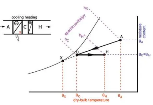
[image:3.612.182.432.320.492.2]Active dehumidification is mechanical moisture removal intended to maintain comfort and protect building materials. There are two primary ways to actively dehumidifierumidify: by condensing moisture using a heat pump refrigerant-based de-humidifier and by adsorbing moisture using a desiccant wheel desiccant dede-humidifier. (We use the less-familiar term adsorption to describe how water molecules adhere to the surface of a material; absorption, in contrast, occurs uniformly throughout a ma-terial.)
Fig. 5.1 Dehumidification Process
In refrigerant based dehumidifier. units, the warm, moist air flows past metal coils cooled using a compression-expansion cycle; water condenses on the coils and collects in a reservoir or is piped to a drain. The cool, dry air then flows past the warm condenser section of the heat pump, leaving the dehumidifierumidifier dryer and warmer than when it entered.
Refrigerant-based dehumidifiers are available as standalone equipment or can be ducted into a whole-building forcedair system. The standalone configuration, used commonly in residential basements, is probably the most familiar. Desiccant-wheel units must have a ducted pathway for the regeneration air flow and to dump the warm, moist air to the outdoors. For this rea-son, desiccant wheel systems are almost always ducted into a whole-building forced-air system. When ducted into a forced-air system, both types of dehumidifier are configured in parallel and not in series with the rest of the system, since both typically use lower flow rates (guaranteeing more contact time) to improve moisture removal.
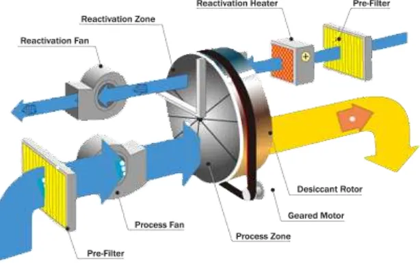
6 SYSTEM PROCESS EXPLANATION
The main components of a desiccant cooling system are shown in figure. The basic process in providing conditioned air may be described as follows:
Atmospheric air enters the slowly rotating desiccant wheel and is dehumidified by adsorption of water. Since the air is heated up by reteaming latent heat. This dehumidified air can flow over the heat ·exchanger (water to air Heat exchanger), where its temperature is significantly falls. This cool and dehumidified air is supplied to room.
(a) Represents evaporative cooling system to cool water for heat exchanger (radiator). Evaporative cooling system consists of convergent portion. From the portion water will flow down and evaporates with air.
(b) Represents fan, which is used to draw the air from room.
(c) Represents transformers, which are used to run the fan (inlet and out Jet). These Transformers reduce the voltage from 240V to l 2V and hence power will be reduced.
[image:4.612.147.454.376.569.2](d) Represents radiator. It is the main component, which cools the air from desiccant wheel and supplies the air to room.
Fig. 6.1. Schematic of Desiccant Wheel based Air Conditioning
EXPLANATION OF THE STAGES OCCURRING IN THE DESICCANT COOLING SYSTEM:
Stage l: Atmospheric air enters the slowly rotating desiccant wheel. Here the atmospheric air gets dehumidified by releasing la-tent heat. Due to this the temperature of air increases and relative humidity decreases.
Stage 2: The dehumidified air is passed over the heat exchanger, where its temperature is falls. This cool and dehumidified air is supplied to the room.
PROBLEM DOMAIN
• Objective is to produce comfort conditions for summer season using the approach of Desiccant Wheel Dehumidier • Humidity Control in Pharmaceutical Industries, Militry Camps, Ordanance Factory.
• Comfort condition for summer season not provided by cooling system in effective way.
More Maintenance required in other dehumidifier.
• Other machines consume more power to produce comfortcondition for human beings.
7 EXPERIMENTAL VALUES AND CALCULATIONS Conditions of air at inlet to Wheel:
DBT = 29 0C
WBT = 25 0C
RH = 72 %
SH = 18.2 g/kg of dry air
At Rotor Speed of 10 rph: 1. Air Inlet Velocity = 1.5 m/s
Conditions of air at Outlet of Wheel: DBT = 45 0C
2. Air Inlet Velocity = 2 m/s
Conditions of air at Outlet of Wheel: DBT = 43.5 0C
3. Air Inlet Velocity = 2.5 m/s
Conditions of air at Outlet of Wheel: DBT = 42 0C
4. Air Inlet Velocity = 3 m/s
Conditions of air at Outlet of Wheel: DBT = 41 0C
5. Air Inlet Velocity = 3.5 m/s
Conditions of air at Outlet of Wheel: DBT = 40 0C
At Rotor Speed of 20 rph: 1. Air Inlet Velocity = 1.5 m/s
Conditions of air at Outlet of Wheel: DBT = 46.5 0C
2. Air Inlet Velocity = 2 m/s
Conditions of air at Outlet of Wheel: DBT = 44.5 0C
Conditions of air at Outlet of Wheel: DBT = 43 0C
4. Air Inlet Velocity = 3 m/s
Conditions of air at Outlet of Wheel: DBT = 42 0C
5. Air Inlet Velocity = 3.5 m/s
Conditions of air at Outlet of Wheel: DBT = 41 0C
At Rotor Speed of 30 rph: 1. Air Inlet Velocity = 1.5 m/s
Conditions of air at Outlet of Wheel: DBT = 48 0C
2. Air Inlet Velocity = 2 m/s
Conditions of air at Outlet of Wheel: DBT = 46 0C
3. Air Inlet Velocity = 2.5 m/s
Conditions of air at Outlet of Wheel: DBT = 45.5 0C
4. Air Inlet Velocity = 3 m/s
Conditions of air at Outlet of Wheel: DBT = 43 0C
5. Air Inlet Velocity = 3.5 m/s
Conditions of air at Outlet of Wheel: DBT = 42 0C
At Rotor Speed of 40 rph: 1. Air Inlet Velocity = 1.5 m/s
Conditions of air at Outlet of Wheel: DBT = 47 0C
2. Air Inlet Velocity = 2 m/s
Conditions of air at Outlet of Wheel: DBT = 45.5 0C
3. Air Inlet Velocity = 2.5 m/s
Conditions of air at Outlet of Wheel: DBT = 46 0C
4. 4. Air Inlet Velocity = 3 m/s
Conditions of air at Outlet of Wheel: DBT = 42.5 0C
5. 5. Air Inlet Velocity = 3.5 m/s
Conditions of air at Outlet of Wheel: DBT = 41.5 0C
than that desiccant materials. Several techniques can be used to estimate the annual energy consumption of hybrid desiccant cooling systems. The most accurate are those that use computer simulations. Although they produce more reliable results than hand-calculation techniques, computer simulations are difficult and expensive to employ routinely as initial screening tools and are therefore appropriate only when additional details are required.
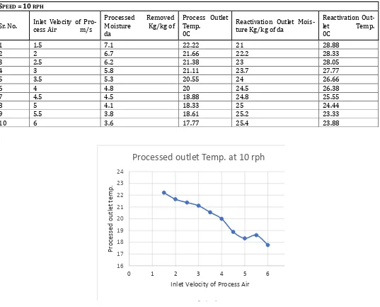
The Following Graphs is Plotted on the Microsoft Excel-2010 at every Graph the inlet velocity of air is plotted on the X-axis. Inlet Velocity is the main parameter to get better performance of the desiccant material dehumidification. At every graph Y-axis is change, Processed outlet temp., Reactivation air Temp., Processed and reactivation removed moisture graph is plotted Vs inlet velocity of air.
[image:7.612.38.575.258.691.2]8 RESULTS AND DISCUSSIONS
Table 1 Desiccant Wheel Rotate at a Speed of 10 rph
16 17 18 19 20 21 22 23 24
0 1 2 3 4 5 6
Proce ss ed ou tle t te m p .
Inlet Velocity of Process Air
Processed outlet Temp. at 10 rph
Series 1
Graph 8.1: Processed Outlet Temp at 10 RPH SPEED = 10 RPH
Sr. No. Inlet Velocity of Pro-cess Air m/s Processed Moisture Kg/kg of Removed da
Process Outlet Temp. 0C
Reactivation Outlet Mois-ture Kg/kg of da
Reactivation
Out-let Temp. 0C
1 1.5 7.1 22.22 21 28.88
2 2 6.7 21.66 22.2 28.33
3 2.5 6.2 21.38 23 28.05
4 3 5.8 21.11 23.7 27.77
5 3.5 5.3 20.55 24 26.66
6 4 4.8 20 24.5 26.38
7 4.5 4.5 18.88 24.8 25.55
8 5 4.1 18.33 25 24.44
9 5.5 3.8 18.61 25.2 23.33
0 2 4 6 8
0 1 2 3 4 5 6
Pr
o
ce
sse
d
r
e
mov
e
d
M
o
istu
re
Inlet Velocity of Process Air
Processed removed Moisture at 10
rph
Series 1
Graph 8.2. Processed Removed Moisture at a 10 RPH
Graph 8.3. Reactivation Outlet Temp. at 10 RPH
Graph 8.4. Reactivation Removed Moisture at a 10 RPH 22
24 26 28 30
0 2 4 6 8
Pr
oc
es
se
d
ou
tl
et
t
em
p.
Inlet Velocity of Process Air
Reactivation outlet Temp. at 10
rph
Graph 8.5 Processed Outlet Temp at 20 RPH
Graph 8.6. Processed Removed Moisture at a 20 RPH
Graph 8.7. Reactivation Outlet Temp. at 20 RPH
0 5 10 15 20 25 30
0 2 4 6 8
Pr
o
cesse
d
r
emo
ved Mo
istu
re
Inlet Velocity of Process Air
Reactivation removed Moisture
at 20 rph
Series 1
Graph 8.8. Reactivation Removed Moisture at a 20 RPH Speed = 20 rph
Sr. No. Inlet Velocity of Pro-cess Air m/s Processed Moisture Kg/kg of da Removed Process Outlet Temp. 0C Reactivation Outlet Mois-ture Kg/kg of da Reactivation Outlet Temp. 0C
1 1.5 6.7 23.88 21 30
2 2 6.6 23.33 22.2 29.44
3 2.5 6.2 23.05 23.2 29.72
4 3 5.7 22.77 23.7 28.88
5 3.5 5.3 22.22 23.9 28.33
6 4 4.8 21.66 24.7 27.77
7 4.5 4.5 20.55 25 27.22
8 5 4.1 20 25.2 26.66
9 5.5 3.8 20.27 25.2 25.55
Graph 8.9 Processed Outlet Temp at 30 RPH
0 1 2 3 4 5 6 7 8
0 2 4 6 8
Pr
o
cesse
d
r
emo
ved Mo
istu
re
Inlet Velocity of Process Air
Processed removed
Moisture at 30 rph
Series 1
Graph 8.10. Processed Removed Moisture at a 30 RPH
Graph 8.11. Reactivation Outlet Temp. at 30 RPH
Graph 8.12. Reactivation Removed Moisture at a 30 RPH Speed = 30 rph
Sr. No. Inlet Velocity of Pro-cess Air m/s Moisture Kg/kg Processed Removed of da
Process Outlet Temp.
0C
Reactivation Outlet Mois-ture Kg/kg of da
Reactivation Out-let Temp.
0C
1 1.5 6.8 24.44 20.7 31.11
2 2 6.5 23.88 22 30.55
3 2.5 6.1 23.33 23 30
4 3 5.75 23.05 23.7 29.5
5 3.5 5.3 23.33 24 28.88
6 4 4.9 22.22 24.5 27.77
7 4.5 4.5 21.66 24.7 26.66
8 5 4.2 21.38 25 25.55
9 5.5 3.8 21.11 25.2 25
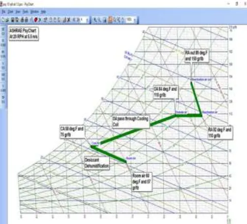
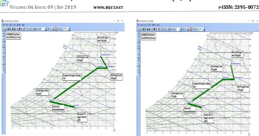
Fig. 8.1: Psychrometric Results at 10 RPH and 1.5 m/s
[image:11.612.321.587.94.314.2]Fig. 8.2: Psychrometric Results at 10 RPH and 3.5 m/s
Fig. 8.3: Psychrometric Results at 20 RPH and 1.5 m/s
[image:11.612.325.576.350.578.2] [image:11.612.48.296.350.562.2]Fig. 8.5: Psychrometric Results at 30 RPH and 1.5 m/s
The inlet and outlet temp values taken from the sling psychrometer at different speed od desiccant wheel and different Process inlet air Velocity. This value plotted on Psychart 2.01.58 Software for the further actual analysis of desiccant Wheel Calculations. The Graphs is plot between Inlet Velocity of air Vs Processed Air Temperature, Processed Removed Moisture, Reactivation Air Temperature, Reactivation Removed Moisture
From the Graphs of Desiccant Wheel Rotate at Different Speed like 10 RPH, 20 RPH,30 RPH, and So on with the Differ-ent Inlet Velocity Clearly shows that Dehumidification Performance Depends on following Parameters Such as:
1. Process Air Inlet Conditions - Moisture
- Temperature
2. Reactivation Air Temperature 3. Process Air Velocity
“From the Trend of Graphs drawns with the Results from the Psychrometric chart Software (PsyChart 2.01.58) in be-tween inlet Velocity and air outlet Temp. for different rotational speeds, the Optimum Speed of desiccant Wheel Used is 30 RPH.”
“From the Experimental Results, Maximum Temperature of Outlet air is Observed with rotational speed of 30 RPH for most of the inlet process Velocity which is an indication maximum moisture Adsorption.”
REFERENCES
1. ISHRAE Handbook
2. Design and Fabrication of Desiccant Wheel Dehumidifier: Er. Amit Tiwari Asst. Professor, Dept. of M.E Dungarpur College of Engg. and Tech., Dungarpur (Raj), India.:
3. Design and Testing of a Liquid Desiccant Dehumidifier: P. R. Armstrong, G. H. Brusewitz ASSOC. MEMBER ASHRAE: 4. Experimental performance study of a proposed desiccant based air conditioning system: M.M. Bassuoni.: Performance
5. An experimental study on the dehumidification performance of a low-flow falling-film liquid desiccant air-conditioner: S. Bouzenadaa, C. McNevinb, S. Harrison c, A. N. Kaabid.:
6. Performance Characteristics of Solid-Desiccant Evaporative Cooling Systems: Ramadas Narayanan, Edward Halawa and Sanjeev Jain.:
7. Solar Air Conditioning System Using Desiccant Wheel Technology, Arfidian Rachman, Sohif Mat, Taib Iskandar, M. Yahya, Azami Zaharim And Kamaruzzaman Sopian, ISBN: 978-960-474-230-1
8. Studies on solid desiccant based hybrid air-conditioning systems P.L. Dhar*, S.K. Department of Mechanical Engineering, I.I.T. Delhi, New Delhi 110 016, India Received 3 August 1999; accepted 27 February 2000
9. A Review on Performance Anyalysis of Different Desiccant Materials for a Desiccant Cooling System Jigar B. Jani, Vinod P. Rajput, Dr.Maharshi Shukla
10. A Review on Internally Cooled Liquid Desiccant Air Dehumidifier Jignesh R Mehta, Niyati M Shah, Krunal N Patel Mechani-cal Engineering Department, Faculty of Technology and Engineering, The Maharaja Sayajirao University of Baroda
11. ASHRAE, 1992, Desiccant Cooling and Dehumidification, Special Publication, American Society of Heating, Refrigerating, and Air Conditioning Engineers, Atlanta, GA.
12. GRI, December 1992, “Dehumidification-A Major Opportunity for Natural Gas,” GRI Technology Focus, Gas Research Insti-tute, Chicago, IL.
AUTHORS
Bhatu Raman Borane
Student M.Tech – Thermal Engineering Godavari College of Engineering, Jalgaon Maharashtra – 425001 India
Dr. V. H. Patil Principal
Godavari College of Engineering Jalgaon Maharashtra – 425001 India
Mr. Archis Phansalkar Project Engineering Manger Vijay Air Conditioning Pvt. Ltd Pune India
Prof. Tushar Koli