p
T
P
e eag
RESEARCH ARTICLE
COMPARISON ANALYSIS OF STATOR RESISTANCE ESTIMATION OF THREE PHASE INDUCTION
MACHINE WITH AIR GAP POWER AND REGRESSION METHODS
Mostafa Bannazadeh
Department of Electricity, Shoushtar Branch, Islamic Azad University, Shoushtar, Iran
ARTICLE INFO ABSTRACT
This paper proposes two online algorithms for estimating stator resistance of an induction motor without using rotor resistance. In this research, we use "air gap power" and "linear regression" methods to estimate resistance of stator in different speeds and torques. These methods are tested using simulation and experimental data from a commercial induction motor. Benefits and defaults of each method will be compared with the other method result. Obtained results of both methods show that estimations of stator resistance in low speeds have been well but air gap method has been presented more accurately rather than linear regression.
©Copy Right, IJCR, 2011, Academic Journals. All rights reserved
INTRODUCTION
Today, induction motors are the most applicable ones in industry. The highlight benefits of these motors are: fastening, simple structure, low manufacturing fees, low weight, higher velocities, easier maintenance, velocity controlling accurately and at last low inertial of rotor. The main problem applying these motors is motion controlling. In control methods of the induction motors, field-oriented Control (FOC) and direct torque control(DTC) methods, dynamical model of the motor is used. These control methods are extremely sensitive to value of dynamical model parameters and as we know, values of the parameters of induction motor vary with the time, and their large variations can seriously degrade control performance of the proposed control methods .So it is necessary to estimate the motor parameter accurately. Resistance of stator is an important parameter of dynamical model of induction motor which changes due to temperature variations. The first research about estimating induction motor parameters to improve controlling the FOC was done by Graces in 1980. The method used included an extra function as a setting reactive power and required much calculation. Wang and Birdwell (1982) suggested a method by using extended Kalman filter, since measuring the tourqe is an important principle in this method, it may not be able to perform this method for big machines. In some references of this research such as 4, 5, 6, 7, 8, 9, 10 and 11 expressed in the last section, a few methods are introduced to simultaneous estimate rotor resistance. As a whole, methods to simultaneous estimate stator resistance are similar to methods used to estimate rotor resistance (time constant of rotor) and divided
*Corresponding author: [email protected]
to four group: spectral analysis techniques – signal injection [13], techniques in terms of observers [14], techniques in terms of model reference adaptive system (MRAS) [15] and other new methods [16 & 18]. This paper consider two methods, air gap power and linear regression to online estimation of stator resistance and compare accurately the result about benefits and defaults of each method.
II. Air Gap Method
By this method, stator resistance( ) is obtained from the steady-state power flow between stator and rotor through the air gap. the steady-state power across the air gap is given by:
(1)
Where is steady-state value of generated torque, is steady-state value of Angular velocity of d–q synchronous reference coordinate frame and p is the number of poles. If input power (P) and magnitude of stator current vector (I) are defined as:
Therefore by using motor dynamical equations, the steady-state input power and the steady-steady-state power dissipated by stator windings are obtained by: [18]
ISSN: 0975-833X
International Journal of Current Research Vol. 3, Issue, 11, pp.413-417, October, 2011
INTERNATIONAL JOURNAL OF CURRENT RESEARCH
Article History:
Received 27th
June, 2011 Received in revised form 25th
August, 2011 Accepted 29th
September, 2011 Published online 30th
October, 2011
Key words:
0
3
)
1
(
E SQ
L
2
3
P
P
in
(4)
2 3R I2
Pcu S
(5)
Since input power is equal to sum of air gap power and dissipated power in stator windings, we have:
(6)
It is clear that we can use (6) to calculate stator resistance if the steady-state value of the generated torqueis available. It is possible to prove that although sign of is not available, but can be expressed in terms of the steady-state values of the reactive power (Q), the stator current magnitude (I) and the angular velocity of the d–q synchronous reference coordinate frame (ωe) as follows: [18]
23 2 0 2 3 2 0 2 2 / ) ( ) ( e e e e T e a I Q a I Ma I Q a K T
(7)So for stator resistance, the following relation is obtained:
2 2
/
]
)
sgn(
))
3
/(
2
(
[
P
p
T
T
I
R
s
e e(8)
Overally, it seems very difficult to identify directly the sign of from the stator variables. But stator resistance is one of the following values in place of appointing sign of :
2 2
1
[
P
(
2
/
3
p
)
T
]
/
I
R
e e(9)
2 2
2
[
P
(
2
/
3
p
)
T
]
/
I
R
e e(10)
Note that, in this paper, the simulations indicate that only one of tow above values is an acceptable answer and the other is extremely High or extremely low and so it is unacceptable. This method answers well in most of torques and speeds.
III. Linear regression method
This method is on the basis of mathematical law "linear regression" and so we call this to the same name. We should know that this method Use Only Voltage and Current Measurements for Online Estimation of the Stator resistance.
A. Parameter Identifiability
The vector voltage and flux-linkage equations of an induction motor in a fixed reference frame could be written as:
(11-a)
(11-b)
(11-c) (11-d)
We can express the above dynamical model as:
V dt j V dt
L R V r r r 1 2 1 (12) Which: dt di L i R V dt d L L
V r S S s S s
r m 1 (13) dt di L i R V i L L L
V r S S S S S S S
r m
(1 )
2
(14)
If rotor flux does not change, it can be written as:
j V dt
V1 1
(15)
According to (12), space vectors
1
1
dt
،
V
V
j
and
dt
V
2 are along the same direction regardless of Rr. Thus it is possible to estimate stator resistance by using linear dependencebetween
dt
V
j
1 and
dt
V
2 . Furthermore, if these space vectors are along the same direction, their cross product must be zero. Thus:
0
Re
v
1dt
v
2*dt
(16)We obtain the following relation by using (13) to (16): [19]
2 2
2
v
Sdt
R
Si
Sdt
(17)
v
dt
i
dt
R
S
S
S
2
Re
*
0
Re
)
1
(
*
2 2
L
Si
S
v
Sdt
L
Si
SEquation (17) needs a state variable filter to calculate derivatives and integrals but the supply frequency ( ) is accessible, we can rewrite this equation as:
3
2
)
(
2 2 2 22 E S S S S S
P
R
i
L
R
v
(18)
We can rewrite equation (17) and (18) by using linear regression as a linear model:
(19)
is the parameter to be estimated:
Y/ U= (20)
Defining appropriate parameters U and Y, an equation would be obtained to estimate stator resistance. Ofcourse this direct calculation will be affected by noise, but this noise will be decreased by averaging.
B. Appropriate definition of parameters U and Y
If in Equation (17), Ls and
L
S= Lls are considered constant,this Equation can be written as
A second-order equation in terms of Rs [see (15)]:
dt
i
dt
v
b
S S*
Re
2
dt
v
i
L
dt
v
c
S S S* S2
Re
)
1
(
2 2
S S
i
L
Which we have:
(22)
(23) And
(24)
Which with:
ac
b
b
y
2
4
(25)a
u
2
(26) Then, by using Linear regression method Rs can be calculatedas follows:
Rs= Y/U (27)
IV. Computer simulation
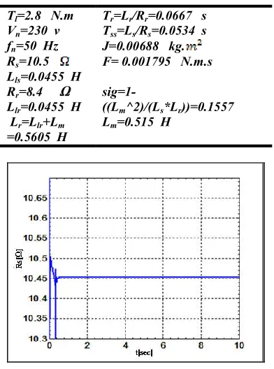
Here, The proposed methods are tested on an induction motor that it's properties are given in table(1) using MATLAB-SIMULINK software .the results of the methods of estimating the parameter are illustrated as in the figures 1 to 11 and comparing with each other described in table (2).
Table1. Properties of tested induction motor
Tr=Lr/Rr=0.0667 s
Tss=Ls/Rs=0.0534 s
J=0.00688 kg. F= 0.001795 N.m.s
p=2
sig=1-((Lm^2)/(Ls*Lr))=0.1557
Lm=0.515 H
Tl=2.8 N.m
Vn=230 v
fn=50 Hz
Rs=10.5
Lls=0.0455 H
Rr=8.4 Ω
Llr=0.0455 H
Lr=Llr+Lm
[image:3.612.338.519.47.186.2]=0.5605 H
[image:3.612.58.302.65.271.2]Fig. 1 Estimation of stator resistance by air gap power method in low speeds (40-120 rpm) and rated torque (2.8 N.m)
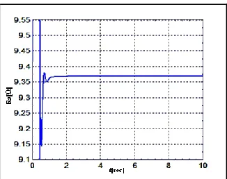
[image:3.612.330.528.212.359.2]Fig. 2. Estimation of stator resistance by air gap power method in low speeds (40-120 rpm) and a half of rated torque (1.4 N.m)
Fig. 3. Estimation of stator resistance by air gap power method in low speeds(40-120 rpm) and one fourth of rated torque (0.7 N.m)
Fig. 4 Estimation of stator resistance by air gap power method in speeds close to the rated one (1400 rpm) and rated torque
(2.8 N.m)
Fig. 5. Estimation of stator resistance by air gap power method in speeds close to the rated one (1400 rpm) and a half of rated
[image:3.612.353.510.399.525.2] [image:3.612.81.277.437.701.2]Fig. 6. Estimation of stator resistance by air gap power method in speeds close to the rated one (1400 rpm) and one fourth of rated
[image:4.612.351.514.50.175.2]torque(0.7 N.m)
Fig. 7. Estimation of stator resistance by linear regression method in low speeds(40-120 rpm) and rated torque (2.8 N.m)
Fig. 8. Estimation of stator resistance by linear regression method in low speeds(40-120 rpm) and a half of rated
torque(1.4N.m)
Fig. 9. Estimation of stator resistance by linear regression method in low speeds(40-120 rpm) and a one fourth of rated
torque(0.7 N.m)
[image:4.612.349.513.213.342.2]Fig.10. Estimation of stator resistance by linear regression method in medium speeds (500 rpm) and rated torque(2.8N.m)
Fig.11. Estimation of stator resistance by linear regression method in rated speeds (1500 rpm) and rated torque(2.8N.m)
Conclusion
We have considered the methods of air gap power and linear regression to estimate the stator resistance and we have obtained the following results by comparing them:
1) The air gap power method estimates the stator resistance better in low speeds (40 – 120 rpm) and torque of the load is not effective on it in these velocities.
2) The air gap power method estimates the stator resistance well in speeds close to the rated one (1400 rpm) from the rated torque to a half of it which has error of less than 5%.
3) The linear regression method estimates the stator resistance better in low speeds(40 – 120 rpm) only to a half of rated torque(1.4 Nm).
[image:4.612.317.554.401.472.2]REFERENCES
[1] Garces, L. J. “Parameter adaption for the speed-controlled static ac drive with a squirrel-cage induction motor,” IEEE Trans. Ind. Applicat., vol.IA-16, pp. 173– 178, Mar./Apr. 1980.
[2] Hisao Kubota, Member, IEEE, and Kouki Matsuse,
Senior Member, IEEE ."Speed Sensorless Field-Oriented Control of Induction Motor with Rotor Resistance Adaptation" , IEEE TRANSACTIONS ON INDUSTRY APPLICATIONS, VOL. 30, NO. 5, SEPTEMBER / OCTOBER 1994.
[3] Joachim Holtz, Senior Member, IEEE, and Thomas Thimm, " Identification of the Machine Parameters in a Vector-Controlled Induction Motor Drive", IEEE TRANSACTIONS ON INDUSTRY APPLICATIONS, VOL. 27, NO. 6, NOVEMBER-DECEMBER 1991. [4] Koyama M.et al., "Microprocessor-based vector control
system for induction motor drives with rotor time constant identification function" ,IEEE Trans. Industry Appl. ,vol . IA-22 ,no.3, pp.453-459,1986.
[5] Ohshin k. et al., "Model reference adaptive system against rotor resistance variation in induction motor drive",IEEE Trans. Ind .Electron.,vol.IE-33,no.3,pp.217-223,1986.
[6] Salvatore, L., S. Stasi, and L. Tarchiono, “A new EKF-based algorithm for flux estimation in induction machines ”, IEEE Trans. Ind. Electron., vol. 40, pp. 496–504, Oct. 1993.
[7] WANG Y.and J.D. BIRDWELL, ,"Dynamic identification of the model parameters for an induction motor", Conference Proceedings of IEEE,Southeastlon, April 1982, Paper CH1749-1,pp. 430-3.
[8] Zai, L., DrMarco, C.L. and Lipo, T.A., “An Extended Kalman Filter Approach to rotor Time Constant Measurement in PWM Induction motor Drives” IEEE Transocrionson industry Applications, vol. 28, no. 1,pp. 96-104, JawFeb. 1992.
[9] K. S. Huang, Q. H. Wu, Senior Member, IEEE, and D. R. Turner, "Effective Identification of Induction Motor Parameters Based on Fewer Measurements " , IEEE TRANSACTIONS ON ENERGY CONVERSION, VOL. 17, NO. 1, MARCH 2002.
[10] M-R. Fbarzadeh-T, G. Faezian, H. Tabatabaei-Y, N. Sargolzael, "A New Variable Structure Control Methodology for Electrical/Mechanical Parameter Estimation of Induction Motor" ,0-7803-78962/ 03/ $17.2003 IEEE.
[11] Jong-Wook Kim, Student Member, IEEE, and Sang Woo Kim, Member, IEEE, "Parameter Identification of Induction Motors Using Dynamic Encoding Algorithm for Searches (DEAS)" ,IEEE TRANSACTIONS ON ENERGY CONVERSION, VOL. 20, NO. 1, MARCH 2005.
[12] Ali Karimi, Muhammad A. Choudhry, Ali Feliachi ,"PSO-based Evolutionary Optimization for Parameter Identification of an Induction Motor",IEEE2007. [13] T. Matsuo and T. A. Lipo, “A rotor parameter
identification scheme for vector controlled induction motor drives,” IEEE Trans. Ind. Applicat.,vol. IA-21, pp. 624–632, May/June 1985.
[14] T. Du, P. Vas, and F. Stronach, “Design and application of extended observers for joint state and parameter estimation in high-performance AC drives,” Proc. Inst. Elect. Eng.—Elect. Power Applicat., vol. 142, no. 2,pp. 71–78, 1995.
[15] H. Sugimoto and S. Tamai, “Secondary resistance identification of an induction-motor applied model reference adaptive system and its characteristics” ,IEEE Trans. Ind. Applicat., vol. IA-23, pp. 296– 303,Mar./Apr. 1987.
[16] C. C. Chan and H.Wang, “An effective method for rotor resistance identification for high-performance induction motor vector control,” IEEE Trans. Ind. Electron., vol. 37, no. 6, pp. 477–482, 1990.
[17] H. Toliyat, M. S. Arefeen, K. M. Rahman, and M. Ehsani, “Rotor time constant updating scheme for a rotor flux oriented induction motor drive,” IEEE Trans. Power Electron., vol. 14, pp. 850–857, Sept. 1999. [18] In-Joong Ha, Member, IEEE, and Sang-Hoon Lee,”An
Online Identification Method for Both Stator and Rotor Resistances of Induction Motors Without Rotational Transducers”,IEEE TRANSACTIONS ON INDUSTRIAL ELECTRONICS, VOL. 47, NO. 4, AUGUST 2000. [19] Juan Luis Zamora and Aurelio García-Cerrada,
Member, IEEE,”Online Estimation of the Stator Parameters in an Induction Motor Using Only Voltage and Current Measurem-ents”IEEE TRANSACTIONS ON INDUSTRY APPLICATIONS, VOL. 36, NO. 3, MAY/JUNE 2000.