ISSN Print: 2331-4222
DOI: 10.4236/wjet.2018.62B004 May 22, 2018 34 World Journal of Engineering and Technology
Flutter Suppression of Long-Span Bridges Using
Suboptimal Control
Lingjun Zhuo
1, Yunjin Dong
2, Xinyu Xu
31Research Center for Wind Engineering, Southwest Jiaotong University, Chengdu, China 2Xihua University, Chengdu, China
3China Railway Eryuan Engineering Group Co., Ltd., Chengdu, China
Abstract
Based on the Theodorsen’s Theory of the aerodynamic forces on wing-aileron, the Scanlan’s Theory is expanded considering a deck-flap system. It is sug-gested that a new forced vibration method can acquire aerodynamic deriva-tives of this deck-flap system theoretically. After obtaining the wind induced forces, a deck-flap equation of motion in time domain is established to inves-tigate its control law. Numerical simulation results indicate suboptimal con-trol law of the deck-flap system can suppress the flutter effectively, and the flutter speed can be increased for desirable purpose.
Keywords
Aerodynamic Force, Deck-Flap System, Flutter Suppression, Control Law
1. Introduction
Flutter is a self-excited motion, which eventually leads to catastrophic damage in bridge structures. Nowadays, with more and more long-span bridges to emerge, finding ways to suppress flutter and increase stability can tackle severe wind-induced problems. Adding stiffness of a girder, application of mechanical dampers are common ways to improve a bridge aerodynamic property. Using active control is a new way to solve these problems.
Some researchers tried to put flaps away from deck in order to omit interfe-rence of aerodynamic forces between deck and flaps and can easily apply Theo-dorsen’s Theory of aerodynamic forces [1]. However, this interference cannot be omitted and can improve aerodynamic property in a way [2] [3].
In this paper, the active control system composes of a deck and flaps symme-trically mounted adjacent to the deck. A deck-flap equation of motion in time
How to cite this paper: Zhuo, L.J., Dong, Y.J. and Xu, X.Y. (2018) Flutter Suppres-sion of Long-Span Bridges Using Subop-timal Control. World Journal of Engineer-ing and Technology, 6, 34-40.
https://doi.org/10.4236/wjet.2018.62B004
DOI: 10.4236/wjet.2018.62B004 35 World Journal of Engineering and Technology
domain is established. Along with a new forced vibration method, aerodynamic forces can be calculated theoretically. In the end, a numerical simulation helps to investigate its control law.
2. Equation of Motion in Time Domain
Flutter analysis is usually done in the frequency domain. The frequen-cy-dependent motion-induced forces should be transformed to time-dependent ones so that they can be applied in the active control analysis. Based on the Scanlan’s Theory, the two dimensional equation of motion can be expressed as:
h h d f
mh c h k h L L+ + = = +L (1a)
d f
I
α
+cαα
+kαα
=M M= +M (1b)where m = mass of the system, I = moment of inertia of the system, ch, cα =
damping of vertical and torsional motion respectively, kh, kα = stiffness of
vertical and torsional motion respectively, L, M = total lift and moment respec-tively, Ld, Md = motion-induced lift and moment of the deck respectively,
f
L , Mf = motion-induced lift and moment of the flaps respectively. The motion-induced forces of the deck can be expressed as:
2 * * 2 * 2 *
1 2 3 4
1 (2 )( )
2
d h h h B h h h
L U B K H K H K H K H
U U B
α
ρ
α
= + + + (2a)
2 2 * * 2 * 2 *
1 2 3 4
1 (2 )( )
2
d h B h
M U B K A K A K A K A
U U B
α α
α
α αρ
α
= + + + (2a)
where ρ = air density, U = wind velocity, B = deck width, h, α = vertical and tor-sional displacement respectively, Kh=ωhB U/ , Kα=ωαB U/ ,
*, ( 1 ~ 4)*
i i
H A i= = aerodynamic derivatives of the deck.
The aerodynamic flaps can be driven on both sides. Figure 1 shows that when flutter of the system is detected, the trailing flap is motivated and the leading flap is locked along with the deck. In this way, Theodorsen’s Theory on wing-aileron forces can be applied [4].
2 * 2 *
5 6
1 (2 )( )
2
f h B h
L U B K H K H
U
β
ρ
β
= + (3a)
2 2 * 2 *
5 6
1 (2 )( )
2
f B
M U B K A K A
U
α
β
αρ
β
= + (3b)
where β = torsional displacement of trailing flap, *, ( 5,6)*
i i
H A i= =
aerody-namic derivatives of the trailing flap.
[image:2.595.206.537.648.723.2]To obtain the aerodynamic derivatives for the deck-flap system, a forced
Figure 1. Deck-flap system [2].
Wind
α
h
DOI: 10.4236/wjet.2018.62B004 36 World Journal of Engineering and Technology
vibration method is proposed. When the system is forced to rotate sinusoidally, displacements of the system can be assumed as:
( )
0 0
0 i t i t
h= α α= eω β β= e ω ϕ+
The total lift and moment are:
2 * * * 2 * * *
2 1 5 2 6 3 3 5 4 6
2 2
2 3
1 (2 ) ( ) ( )
2
1 (2 ) ˆ ˆ
2
B
L U B K H l H l H K H l H l H
U B
U B KH K H
U α ρ α α ρ α = + + + + + = +
(4a)
2 2 * * * 2 * * *
2 1 5 2 6 3 3 5 4 6
2 2 2
2 3
1 (2 ) ( ) ( )
2
1 (2 ) ˆ ˆ
2
B
M U B K A m A m A K A m A m A
U B
U B KA K A
U α ρ α α ρ α = + + + + + = +
(4b)
where l m ii, ( 1,2,3,4)i = = a combination of flap’s amplitude and its phase an-gle, H A iˆ , ( 2,3)i ˆi = = new derivatives of the system in the forced vibration
me-thod.
Using the same way in the regular forced vibration method, the new deriva-tives can be acquired from:
( )
( )
2 3 2 3 3 2
0 0
2 2
ˆ Im ˆ Re
H F L H F L
B B
ρ ω α ρ ω α
= =
( )
( )
2 4 2 3 4 2
0 0
2 2
ˆ Im ˆ Re
A F M A F M
B B
ρ ω α ρ ω α
= =
And their relations can be put as:
[
]
2 1 2
2 3 5 6
3 4 3
ˆ 1 0
ˆ 0 1
T
H l l
H H H H
l l H =
(5a)
[
]
2 1 2
2 3 5 6 3 4
3
ˆ 1 0
ˆ 0 1
T
A m m
A A A A
m m A =
(5b)
As seen from above, it needs only a few tests to figure out a statically indeter-minate matrix for solving the aerodynamic derivatives. Thus, inserting Equa-tions (2) and (3) into Equation (1), and transforming it into Laplace domain with zero initial conditions gives:
2
[Ms +Cs K q F+ ]= (6) where mB M I = , h c B C cα = , h k B K kα = , / h B q α = , L M Q F Q =
A common way to transform wind induced forces into time domain is a ra-tional function approximation by Roger [5]. The details can be found in any aeronautical textbook. Each coefficient Qij can be expressed as:
0 1
2 1
N
ij ij ij
ij m
m m
s
Q A A s A
s γ
= −
= + +
+
DOI: 10.4236/wjet.2018.62B004 37 World Journal of Engineering and Technology
Combined with aerodynamic derivatives acquired from forced vibration me-thod, each coefficient can be obtained through the rational function approxima-tion.
3. Feedback Control
Equation of motion can be rewritten as:
0 1 0 1
2 1 2 1
( N ) ( N )
d m d m
m m m m
s s
Mq Cq Kq q A A s A q q B B s B
s γ s γ β
= − = −
+ + − + + = + +
+ +
∑
∑
In order to study control law for stabilization, the equation of motion can be put in the state space form:
x Ax Bu y Cx = + = (8) where, 3 a am X X x X X = ,
1 1 1 1
3
1
2
0 0 0
0 0
0 0
d d m
m
I
M K M C q M A q M A
U I I A B U I I B γ γ − − − − − − − − = − , 1 0 0 0 M G B − =
, u=βc, y=
[ ]
X ,0 0 I C = , 2 2 2 d B
M M q A
U
= − , C C q= − dUB A1, K K q A= − d 0,
0 0 c G k kβ = .
Optimal output control is a mature way [3] [6], but it needs all the state vector to be measured, which isn’t easy in the deck-flap system. On the other hand, suboptimal output control can be exerted through only a few state vector. It’s more reliable in wind tunnel experiments [7]. Suppose that the control is gener-ated via output linear feedback gains:
con
u= −K y (9)
where Kcon = feedback gain matrix to be determined.
To solve the suboptimal output control problem is to figure out a optimiza-tion of the averaged performance index:
0
1 ( )
2
T T
J=
∫
∞ x Qx u Ru dt+ (10)DOI: 10.4236/wjet.2018.62B004 38 World Journal of Engineering and Technology
Inserting the output equation from the state space form and performing a simple mathematical operation yields
0
1
0 0
1 ( )
2
1 ( ) 1
2 2
T T T T
con con
T T T T
con con
QJ x Qx x C K RK Cx dt
x Q C K RK C xdt x Q xdt
∞
∞ ∞
= +
= + =
∫
∫
∫
(11)It appears that Kcon is the solution of three equations:
1 0 1 min min
2 T
J=
∫
∞x Q xdt (12a)( )
con con
x A x= = A BK C x− (12b)
1 0
T
con con
PA +A P Q+ = (12c)
4. Numerical Simulation
A plate with decks on both sides is simulated to see the results of the application of active control. The deck is 40 meters wide, mass of the deck
20000 /
m= kg m, moment of inertia I=4.5 10× 6kg m m⋅ 2/ , 0.1788
h Hz
ω = ,
0.5028Hz α
ω = , air density ρ=1.225 /kg m3, the width of flap is 3 m.
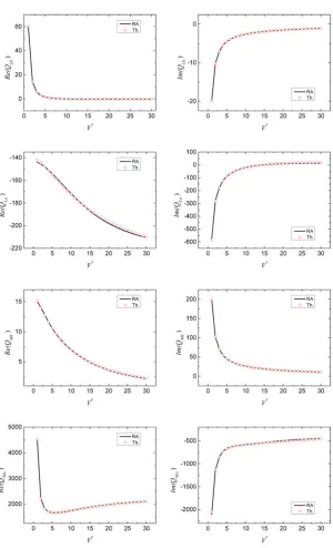
First, its aerodynamic forces should be transformed through the Roger ap-proach, as shown in Figure 2.
The aim of the active control is to suppress flutter up to 159 m/s. when using optimal control, the value of its gain is:
[ 0.5373 2.8299 3.6154 1.8600 0.0069 1.0017 2.5807 6.5471 1.6502 3.5028 1.0229 4.3174]
op
K = − −
− − − −
Figure 3 shows the responses of the deck-flap system under optimal control in the wind speed of 159 m/s, when the system is exerted external forces.
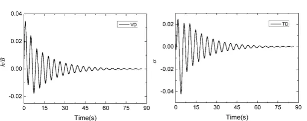
The value of gain after applying suboptimal control is:
[
0.0098 0.6779]
conK = −
And its responses in the wind speed of 159 m/s is shown in Figure 4, when exerted with external forces.
The numerical example shows that both control laws can suppress flutter in the high wind speed. Despite the quick response under optimal control, it's hard to track all the parameters in state vector. The suboptimal control provides a brief strategy to suppress flutter with few parameters in state vector. In this case, the control law depends on the vertical and torsional displacements. For wind tunnel experiments, the two displacements are very common and easy to track.
5. Conclusions
The modeling of deck-flap system is studied in this paper. A state space form of equations of motion in time domain are obtained through Roger’s approach.
DOI: 10.4236/wjet.2018.62B004 39 World Journal of Engineering and Technology Figure 2. Rational approximation for motion-induced forces.
[image:6.595.223.528.584.703.2]DOI: 10.4236/wjet.2018.62B004 40 World Journal of Engineering and Technology Figure 4. Time-history of system displacements under suboptimal control.
aerodynamic derivatives of the deck-flap system with only a few wind tunnel tests. But its accuracy need to be checked.
The numerical simulation shows that the aerodynamic flaps can suppress flutter on desired wind speed. Although feedback gain from the optimal control effectively stabilize the system in high wind speed, its state vector is not that easy to track. The suboptimal control can greatly suppress the vibration and relies on a few state vector parameters.
References
[1] Kobayashi, H. and Nagaoka, H. (1992) Active Control of Flutter of a Suspension Bridge. Journal of Wind Engineering and Industrial Aerodynamics, 41, 143-151. https://doi.org/10.1016/0167-6105(92)90402-V
[2] Hansen, H.I. and Thoft-Christensen, P. (1998) Active Vibration Control of Long Suspension Bridges Using Flaps. Proceedings of the 2nd World Conference on Structure Control, Wiley, Singapore.
[3] Guo, Z.W. and Ge, Y.J. (2012) A New State-Space Model for Self-Exited Forces and Flutter Automatic Analysis of Long Span Bridges. 7th International Cooloquium on Bluff Body Aerodynamics and Applications (BBAA7), Shanghai, China.
[4] Theodorsen, T. (1935) General Theory of Aerodynamic Instability and the Mechan-ism of Flutter. Aerodynamic Flutter, American Institute of Aeronautics and Astro-nautics, No. 496.
[5] Dowell, E.H., Clark, R., Curtiss Jr., H.C., et al. (2004) A Modern Course in Aeroelas-ticity. 4th Edition, Kluwer Academic Publishers.
[6] Wilde, K. and Fujino, Y. (1998) Aerodynamic Control of Bridge Deck Flutter by Ac-tive Surfaces. Journal of Engineering Mechanics, 124, 718-727.
https://doi.org/10.1061/(ASCE)0733-9399(1998)124:7(718)
[7] Librescu, L. and Marzocca, P. (2005) Advances in the Linear/Nonlinear Control of Aeroelastic Structural Systems. Atca Mechanica, 178, 147-186.
![Figure 1. Deck-flap system [2].](https://thumb-us.123doks.com/thumbv2/123dok_us/9290662.425045/2.595.206.537.648.723/figure-deck-flap-system.webp)