Design of a multi-DOF cable-driven mechanism of a miniature serial
manipulator for robot-assisted minimally invasive surgery*
Antonia Tzemanaki
1, Lukasz Fracczak
2, David Gillatt
3, Anthony Koupparis
3, Chris Melhuish
1,
Raj Persad
3, Edward Rowe
3, Anthony G. Pipe
1, and Sanja Dogramadzi
1Abstract— While multi-fingered robotic hands have been de-veloped for decades, none has been used for surgical operations.
µAngelo is an anthropomorphic master-slave system for tele-operated robot-assisted surgery. As part of this system, this paper focuses on its slave instrument, a miniature three-digit hand. The design of the mechanism of such a manipulator poses a challenge due to the required miniaturization and the many active degrees of freedom. As the instrument has a human-centered design, its relation to the human hand is discussed. Two ways of routing its cable-driven mechanism are investigated and the method of deriving the input-output functions that drive the mechanism is presented.
I. INTRODUCTION
Technical surgical competence, such as manual dexterity, is a basic and very important component for a surgeon [1]. Surgical robots can offer improved precision and dexterity [2], especially when the manipulation of the surgical instru-ments and control of the surgical robot comes naturally to the surgeon.
We have previously presented the concept of anthropomor-phic surgical instruments in order to help reduce the ‘cogni-tive gap’ between the current manipulation of robot-assisted minimally invasive surgery (RAMIS) instruments and the surgeon’s natural hand movements [3]. The µAngelo sys-tem for RAMIS aims at higher dexterity and precision required for surgical tasks and shortened training time for new surgeons. It utilizes an anthropomorphic approach: the surgeon controls hand-like instruments by wearing a lightweight sensory exoskeleton (Fig. 1) [4]. The instrument has 13 actuated degrees of freedom (DOF) in total and accommodates a cable-driven mechanism inside the digits and through the shaft.
Tendon driven mechanisms impose coupling of the joints’ motion and complicate their actuation and control, while there is also the risk of tendons breaking during an operation. Other methods include the use of shape memory alloy [3], al-though grasping forces seem insufficient for use in abdominal surgery. Hong et al. use a parallel rigid link mechanism with the drive unit integrated into the instrument’s shaft [5]. MICA also has its motors integrated into the instrument in order to aim for versatility and low cost as the tool is detachable [6].
*This work has been supported by the Bristol Urological Institute antonia.tzemanaki@brl.ac.uk
1Bristol Robotics Laboratory, Frenchay Campus, University of the West
of England, Bristol, UK
2Institute of Machine Tools and Production Engineering, Lodz University
of Technology, Poland
3Bristol Urological Institute, Southmead Hospital, Bristol, UK
[image:1.612.361.511.624.706.2](a) (b)
Fig. 1. µAngelosurgical system: (a) 3-digit surgical instrument and (b) sensory hand exoskeleton for remote control
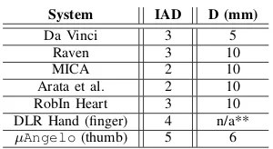
The literature shows that there is a compromise between the size of a manipulator and the number of its independently actuated DOF. For example, MICA’s end-effector (universal joint) is controlled via a cable-pulley system via the 10 mm diameter shaft. Both the Da Vinci [7] and the Raven instruments [8] use a cable and pulley system as well. The shaft of Da Vinci instruments is 8 mm in diameter, with a few exceptions at 5 mm. The Robin Heart system for cardiac surgery has a tool with changeable tooltips and 3 DOF [9]. In a non-surgical context, the DLR Hand has fingers that have 4 actuated DOF using an antagonistic pair of tendons for each DOF and a total of 8 motors, while its size is comparable to a human hand [10]. Table I compares the size and active DOF of robotic digits (of surgical instruments or hand). Note that opening and closing of functional end-effector has not been included in the number of DOF.
In this paper, we focus on the cable-driven mechanism of theµAngeloinstrument. Although it resembles a miniature hand, we believe that exact imitation would be unnecessary for RAMIS applications. Therefore, the ‘anthropomorphic’ concept is compared to the human hand, demonstrating their similarities as well as their differences such as the relation of the human hand tendons and the instrument’s mechanism.
TABLE I
COMPARISON OF CABLE-DRIVEN MECHANISMS IN ROBOTIC
INSTRUMENTS OR FINGERS
System IAD D (mm)
Da Vinci 3 5
Raven 3 10
MICA 2 10
Arata et al. 2 10
RobIn Heart 3 10
DLR Hand (finger) 4 n/a**
µAngelo(thumb) 5 6
Two ways of routing the cable-driven mechanism are in-vestigated and the approach for deriving the input-output functions relating the cable pull to the angular position of the joints are demonstrated.
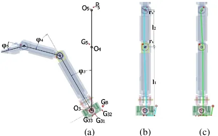
[image:2.612.111.247.253.400.2]As its ‘index’ and ‘middle’ fingers are identical and have 1 DOF less than its ‘thumb’, the description of the mechanism will center on the ‘thumb’. It has 5 DOF (Fig. 2), each of which is controlled by an antagonistic pair of cables, with 2 DOF having axes that share a common origin (1 and 3). The current prototype was 3D printed with a 4mm inner diameter of the shaft. The small size makes it difficult to incorporate pulleys into the mechanism apart from the 1 mm shaft of each joint. Unlike some of the aforementioned designs [11], [12], motors are located outside the instrument. We believe that this can reduce the cost of the motors, as their size is of little importance.
Fig. 2. Degrees of freedom of the thumb, their axes and names of links (l0= 33.6mm,l1= 27.8,l2= 19.5mm)
II. ANTHROPOMORPHISM IN THEµAN G E L O INSTRUMENT
While the human hand digits (fingers and thumb) are an intricate mechanism, the µAngelo instrument provides a carefully chosen subset of the human functional behavior.
A. Structure
For precision grasping in surgery, the thumb, index and middle finger are used [13]. For this reason and to keep the diameter of the instrument minimal, the µAngelosurgical instrument has only three digits. The index and the middle finger of the human hand have 3 phalanges, while the thumb has 2. However, the first metacarpal bone is ossified in the same manner as the phalanges, and this has led anatomists to regard the thumb as having 3 phalanges [14]. Similarly, each µAngelodigit has three links.
Beyond being a simple miniature hand replica, the instru-ment could have digits equipped with a different surgical tip (link 3 in Fig. 2). It would then be an extension to the surgeon’s hand with added versatility, making it possible to perform tasks that they cannot do using just their hands. This offers the possibility for one surgeon to perform actions that normally require an assistant [3]. There are two types of possible fingertips:
• Interchangeable ones, fitting over the digit’s last link: a)
single surfaced, e.g. hook, scalpel, which are carried by
one digit and b) double surfaced, e.g. graspers, needle holders, clamps etc., which require two digits (middle finger and thumb) in order to form the tool.
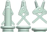
• Permanent ones that have an intricate mechanism in-cluded inside the digit. For example, irrigation requires a tube inside the digit and shaft, while scissors involve two surfaces on one digit (Fig. 3) as well as an external button in the master device for the surgeon to control opening/closing. The actuation mechanism presented in this paper does not include this type of end-effectors, however, the design for such grippers is expected to follow the corresponding mechanism presented in [15].
B. Degrees of Freedom
The index and middle fingers comprise 3 joints each. Two are responsible for flexion/extension of the phalanges (IP1 joints) while the MCP controls flexion/extension and
abduction/adduction. The thumb has 3 joints with the addi-tion of the CMC which offers pronaaddi-tion/supinaaddi-tion, espe-cially important for opposition [16]. The index and mid-dle finger of the µAngelo each have two 1-DOF joints (flexion/extension) and one 2-DOF (flexion/extension and abduction/adduction), while its thumb has three 1-DOF joints (flexion/extension – 5, 4 and abduction/adduction – 2 in Fig. 2) and one 2-DOF joint (flexion/extension and pronation/supination – 3 and 1 in Fig. 2). The joints of theµAngeloare simple rotary joints with range of motion similar to the corresponding joints of the hand, apart from DOF 3 of the instrument’s thumb which has a range of180◦.
Fig. 3. Example of scissors on a digit’s last link [15]
C. Actuation
The digits of the human hand are remotely controlled; there are no muscles inside them. They are located in the palm and in the mid forearm, connected to the bones of the fingers by tendons, which pull on and move the joints. The exact actuation system is complex with each joint action controlled by one or more tendons. Likewise,µAngelo is controlled via a cable-driven mechanism which is simpler, but still maintains the principal quality of the muscular actuation: each joint is controlled by a pair of antagonistic cables. In the human hand, the agonist-antagonists control the stiffness of the joints and the accuracy of the movement by co-contraction [17]. The 13 rotary DOF of theµAngelo are, hence, actuated by 13 motors.
The digits also include smaller bones (sesamoids) which provide a smooth surface for tendons to slide over similarly to theµAngelocables that slide over the shafts of the joints.
1IP: interphalangeal, MCP: metacarpophalangeal, CMC: carpometacarpal,
[image:2.612.391.474.413.469.2]III. CABLE-DRIVEN MECHANISM
As mentioned above, the following analysis will focus on the ‘thumb’ (5-DOF digit) of the instrument as the other two 4-DOF digits are less complex, while the method of finding the driving equations can be derived from that of the thumb. The thumb has 4 joints and 5 DOF and, as the aim is high precision when trying to imitate the surgeon’s digits using the exoskeleton, it has 5 pairs of antagonistic cables. Each pair is attached to the link located above the corresponding joint. This means that for DOF{5}cable ‘J5’ is attached to link ‘3’ (Fig. 2). Likewise, cable ‘J4’ is attached to link ‘2’, ‘J3’ is attached to link ‘a’, ‘J2’ to link ‘1’ and ‘J1’ to link ‘b’. Tension in the cables is assumed to be constant.
Cable ‘J5’ has the most complex control because its length is not only affected by DOF 5, but also by DOF 4, 3 and 2 (DOF 1 does not contribute to any change on cables ‘J5 ’-‘J2’, as its axis coincides with the axis of the digit as well as with the path of these cables). Therefore, we will focus on cable ‘J5’, as the equations that drive the other cables can be
derived in a similar manner. Section III-A investigates two ways of routing the cable inside the digit as well as presents the method of deriving the equations of the cable’s motion as affected only by DOF 3, 4 and 5. Section III-B discusses the effect of DOF 2 has on the same cable.
A. Cable routing
Unlike robotic hands and grippers of a larger size,
µAngelolacks the space to accommodate pulleys or sheaths that will define specific cable paths inside the digit. In order to achieve manipulation, a unique strategy of variable contact cable topology is hereby used. The following analysis distinguishes between cable routing and the paths that occur during operation. In order to find the path for each cable, it is required to determine the key contact points that limit the space that the cable can move in. These points can be found from the design and are depicted in Fig. 4(a), while, generally,Gxdenotes a point that is referenced in frame{x}.
• P: position of the ‘locking’ pin on link ‘3’, where the cable of each joint is attached
• G5: narrowing of the shaft of link ‘2’
• G31andG33: anti-diametrical points of the through hole of link ‘a’ (calculating the inner diameter of a bearing placed inside this link)
• G32: edge of link ‘a’.
• GB: point on the instrument’s main shaft, where cable ‘J5’ exits the thumb and enters a sheath of constant
length until it connects to the actuating motor. This point belongs to the reference frame of the instrument{B}.
The coordinates of each of these points are given in Table II with respect to their reference frame (e.g. P5 is measured with regards to frameO5. The distances between the reference frames (joint axes) are shown in Fig. 2, while the shaft of each joint has a radius ofrs= 0.5mm.
Fig. 4(b) and (c) demonstrate two different methods of routing the cable that drives DOF 5. The manipulator shown is atφ2=φ3=φ4=φ5= 0. In (b), cable ‘J5’ (cyan) starts
(a) (b) (c)
Fig. 4. (a) Key points of the digit and two ways of cable routing: the cable is tangential to (b) the ‘front’ of theO4shaft or (c) the ‘back’
TABLE II DESIGN PARAMETERS
Point Ref. frame X(mm) Y(mm)
P5 {5} 1 1.5
G5 1.2 16.3
G31
{3}
0.75 2.5
G32 5 2.5
G33 0.75 2.5
P2 {2} 1.25 1.5
GB {B} 5.95 2.5
at point P5 and it is then tangential to an arc belonging to the ‘front’ (left in Fig. 4) side of the O5 shaft. It extends vertically until it touches the ‘front’ side of the O4 shaft, continues to pointG31, throughG32and finally exits atGB. In (c), the route is similar with the difference that the cable (green) is now tangential to the ‘back’ (right in Fig. 4) side of theO4 shaft. Below, these two routes are denoted by Lb andLc (to match the representation of Fig. 4).
1) Lb routing: Depending on φ3-φ5, the cable will pass
through all or some of the key points of Fig. 4. The initial position as described in the previous paragraph can be symbolized as follows:
P5→S(O5)→S(O4)→G31→G32→GB
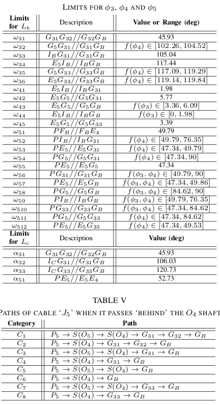
where S(Oi) denotes that the cable is tangential to the Oi shaft (‘front’ side). There are 22 possible paths for this configuration, denoted byBi and summarized in Table III. The specific path that the cable follows depends onφ3−φ5.
Using the limits shown in Table IV (ω31-ω36forφ3,ω41-ω45
forφ4 andω51-ω512forφ5), the combination ofφ3−φ5can
be classified into 50 different categories. For example, B6
occurs whenφ3∈[0, ω31],φ4∈[ω42,90]andφ5∈[0, ω55]. The limits can be functions ofφ3 and/or φ4; the method of findingω32andω43is shown in the Appendix as an example. At the initial position, the length of the cable is:
(1) LB0=P E5+
_
E5FB+l2+ _
E4IB+IBG31+G31G32+G32GB
where E5 is a tangential point on shaft O5 (Fig. 5a); FB is the point where the cable intersects the horizontal from
O5; E4 is a tangential point on shaft O4; IB is a second tangential point on shaftO4as the cable extends toG31. The above distances are calculated by equations (2)-(9). Likewise, equations can be derived for each category of Table III.
(2) R=√x2
[image:3.612.317.542.48.188.2]TABLE III
PATHS OF CABLE‘J5’WHEN IT PASSES‘IN FRONT OF’THEO4SHAFT
Category Path
B1 P5→S(O5)→S(O4)→G31→G32→GB
B2 P5→S(O4)→G31→G32→GB
B3 P5→G31→G32→GB
B4 P5→S(O5)→G31→G32→GB
B5 P5→G5→G31→G32→GB
B6 P5→S(O5)→G5→G31→G32→GB
B7 P5→S(O5)→S(O4)→G31→GB
B8 P5→S(O4)→G31→GB
B9 P5→G31→GB
B10 P5→S(O5)→G31→GB
B11 P5→G5→G31→GB
B12 P5→S(O5)→G5→G31→GB
B13 P5→GB
B14 P5→G5→GB
B15 P5→S(O5)→GB
B16 P5→S(O5)→G5→GB
B17 P5→S(O5)→S(O4)→GB
B18 P5→S(O4)→GB
B19 P5→G33→GB
B20 P5→G5→G33→GB
B21 P5→S(O5)→G5→G33→GB
B22 P5→S(O5)→G33→GB
(3) P E5=
√
R2−r2 s
(4)
_
E5FB=πrs180
180−atanypxp−acosrsR−φ5
(5)
_
E4IB=πrs180(ω41−φ4)
(6) IBG31=
√
O4G231−rs2
(7) O4G31=
q x2
G31+(l0+yG31) 2
(8) G31G32=xG32−xG31
(9) G32GB=
√
O3G2B+O3G232−2·O3GB·O3G32·
·cos
atanyG32 xG32
+atanyGB xGB−φ3
2) Lc routing: This is similar to Lb, with the exception that the cable is tangential to the back of shaft O4. This
simplifies the computation greatly with only 8 possible paths (Table V). The cable length at the initial position is:
(10) LC0=P E5+
_
E5FC+FCE4+ _
E4IC+ICG31+G31G32+G32GB
whereE5andFCare tangential points on shaftO5(Fig. 5b);
E4is a tangential point on shaftO4;ICis a second tangential point on shaft O4 as the cable extends to G31. The above distances are calculated:
(11)
_
E5FC=πrs180
270−atanxpyp−acosrsR−acos2rsl 2 −φ5
(12) FCE4=2
q
(l2 2)
2 −r2
s
(13)
_
E4IC =πrs180
180−acos2rs l2 −acos
rs O4G31−atan
xG31 xG31+l0+φ4
(a) (b)
Fig. 5. Close up of a)Lband b)Lcrouting whenφ3=φ4=φ5= 0
(not actual dimensions)
TABLE IV LIMITS FORφ3,φ4ANDφ5
Limits
forLb Description Value or Range (deg)
ω31 G31G32//G32GB 45.93
ω32 G5G31//G31GB f(φ4)∈[102.26,104.52]
ω33 IBG31//G31GB 105.04
ω34 E5IB//IBGB 117.44
ω35 G5G33//G33GB f(φ4)∈[117.09,119.29]
ω36 E5G33//G33GB f(φ4)∈[119.14,119.84]
ω41 E5IB//IBG31 1.98
ω42 E5G5//G5G31 5.77
ω43 E5G5//G5GB f(φ3)∈[3.36,6.09]
ω44 E5IB//IBGB f(φ3)∈[0,1.98]
ω45 E5G5//G5G33 3.39
ω51 P FB//FBE4 49.79
ω52 P IB//IBG31 f(φ4)∈[49.79,76.35]
ω53 P E5//E5G31 f(φ4)∈[47.34,49.79]
ω54 P G5//G5G31 f(φ4)∈[47.34,90]
ω55 P E5//E5G5 47.34
ω56 P G31//G31GB f(φ3, φ4)∈[49.79,90]
ω57 P E5//E5GB f(φ3, φ4)∈[47.34,49.86]
ω58 P G5//G5GB f(φ3, φ4)∈[84.62,90]
ω59 P IB//IBGB f(φ3, φ4)∈[49.79,76.35]
ω510 P G33//G33GB f(φ3, φ4)∈[47.34,84.62]
ω511 P G5//G5G33 f(φ4)∈[47.34,84.62]
ω512 P E5//E5G33 f(φ4)∈[47.34,49.53] Limits
forLc Description Value (deg)
α31 G31G32//G32GB 45.93
α32 ICG31//G31GB 106.03
α33 ICG33//G33GB 120.73
α51 P E5//E5E4 52.73
TABLE V
PATHS OF CABLE‘J5’WHEN IT PASSES‘BEHIND’THEO4SHAFT
Category Path
C1 P5→S(O5)→S(O4)→G31→G32→GB
C2 P5→S(O4)→G31→G32→GB
C3 P5→S(O5)→S(O4)→G31→GB
C4 P5→S(O4)→G31→GB
C5 P5→S(O5)→S(O4)→GB
C6 P5→S(O4)→GB
C7 P5→S(O5)→S(O4)→G33→GB
C8 P5→S(O4)→G33→GB
3) Comparison: Despite the computational simplicity of routingLc, simulation shows that it is not ideal. In fact, DOF 4 almost cancels out the effect that DOF 5 has on cable ‘J5’. This can be seen in Fig. 6 and 7, where the length difference (or cable pull) is shown for both routes for the whole range of one DOF while the other are at constant angles. These graphs basically simulate the effect of each DOF on the cable as if it was independent from the other. RoutingLb seems to be the one that will give the most accurate results as otherwise, it would be possible to achieve more than one set of solutions with the same pull usingLc. For example, forφ2= 20◦ (for DOF 2 contribution, see Section III-B) and φ3 = 135◦, if φ4=φ5, the cable pull is always 5.85 mm for any value of φ4, φ5∈[0,90].
DOF 3 and 5 have an almost identical effect in both cases, especially when other DOF are close to 0◦. However, for greater angle values,Lb gives a greater (although constant) length difference. This is also beneficial as actuation can be more precise since the resolution is higher (a greater cable length range corresponds to the same angular range).
[image:4.612.55.301.514.712.2]motors for best resolution. Using Lb, we can find that the maximum pull for ‘J5’ happens atφ2= 35◦,φ3= 129.49◦
andφ4=φ5= 90◦ (categoryB20 in Table III) and is11.7
[image:5.612.90.263.106.241.2]mm. Using this maximum, we can find the gear radius.
Fig. 6. Difference in cable length as a function of one DOF when the other are at 0◦
Fig. 7. Difference in cable length as a function of one DOF when the other at a constant value
B. Abduction-adduction
DOF 2 of the instrument’s ‘thumb’, as seen in Fig 2, is the corresponding abduction/adduction motion of the human thumb and hence its axis is perpendicular to the axes of DOF 3, 4 and 5. In order to include the effect that DOF 2 has on cable ‘J5’, we use the superposition principle: the total cable
pull is the sum of the difference in length caused individually by DOF 2 and the combination of DOF 3, 4 and 5.
The length difference caused by DOF 2 is calculated from shaft O5, point G5 or shaft O4 until point G31, GB or
G33, depending on φ3-φ5 and the categories of Table III. For example, forB13andB15the cable length is calculated from shaftO5untilGB and subtracted from that of the initial position (when all joints are at 0◦).
IV. CONCLUSION
The paper describes a theoretical model of the cable-driven mechanism of theµAngeloinstrument. The high number of
[image:5.612.338.527.168.355.2]cables in combination with the narrow digit shafts imposes a complex and computationally expensive way of actuation. Fig. 8 depicts the instrument with all cables connected to the gears of its 13 motors. Although evidence is sparse, studies suggest that 3 digits are adequate for precision grasping tasks [13], [18]. This finding is supported by our medical collaborators. Furthermore, the design follows the utilities of the human hand, such as supination, adduction and rotation, as they are described in Section II.
Fig. 8. Instrument with all cables attached to the gears of the motors
The model accounts for all DOF acting on each cable. However, since each joint is controlled by an antagonistic pair of cables, it is important to create a model for both the agonist and antagonist as, in some joints of the instrument, the models of the two cables are not identical. This is more evident in the effect that DOF 3 has on ‘J5’ and ‘J4’ of the thumb as both cables of each pair exit atGB and hence the cable paths are non-symmetrical. In order to account for this difference in certain DOF, a spring can be added between the antagonist and the motor, to ‘absorb’ the difference in cable pull. Initial experiments showed that the compliance introduced by the springs contributed to some inaccuracy in the end-effector’s position (error with mean of 3.4 mm,
σ= 2.2). Furthermore, assumptions, such as friction between cables and cable elasticity being negligible, can also have an impact on the accuracy of the model. In future work, the agonist and antagonist of each DOF can be actuated by 2 motors instead of one as in [10].
APPENDIX
In the following equations,xi andyi denote the xandy coordinate of pointi with regards to its reference frame as presented in Table II.
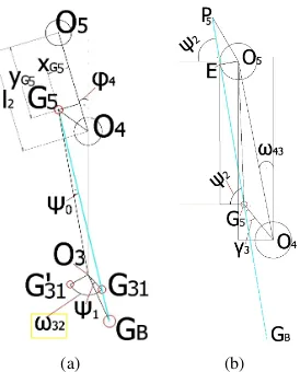
1) Calculation of ω32: When φ3 = ω32, the points G5,
G31andGB are aligned as shown in Fig. 9a, hence, we can writeG5G31//G31GB.G031 is the pivot point whenφ3= 0
and G31 when φ3 = ω32, i.e. the angle between G031 and
G31is ω32. Using cosine law, we get:
ψ0=acos
O3G25 +G5G231−O3G231 2·O3G5·O3G31
[image:5.612.88.261.271.482.2]
(a) (b)
Fig. 9. Geometry for calculation ofω32andω43(not actual dimensions)
where:
O3G5=
s
O4G5sin
φ4+atan
xG5 l2−yG5
2 +
+
O4G5cos
φ4+atanl2xG−yG55+l0
2
O4G5=
q x2
G5+(l2−yG5) 2
O3G31=
q x2
G31+y 2 G31
G5G31=
q
(xG31+O4G5x) 2
+(l0+yG31+O4G5y) 2
O4G5x=O4G5sin
φ4+atan
xG5 l2−yG5
O4G5y=O4G5cos
φ4+atanl2xG−yG55
Again, using cosine law, we can derive lengthG5GB as the root of the polynomial:
G5G2B+2O3G5·cosψ0·G5GB+O3G25−O3G2B=0 (Iβ)
We also have
ψ1=acos
O3G2B+O3G231−G31G2B
2·O3GB·O3G31 (Iγ)
whereG31GB=G5GB−G5G31 andO3GB=
q x2
GB+y2GB. Finally,
we get:
ω32=180−γ0−γ1−ψ1 (I)
whereγ0=atan xG31
yG31 andγ1=atan xGB yGB.
2) Calculation of ω43: When φ4 = ω43, the cable is
tangential to the O5 shaft and passes straight through G5
andGB (Fig. 9b), i.e.E5G5//G5GB. We have
γ3=180−asinO5rsG5−atan yG5 xG5−atan
l2−yG5
xG5 (IIα)
whereO5G5=
q x2
G5+y2G5. For angle ψ2, there are two cases;
i) whenGB is on the right side and ii) left side ofO4:
ψ2=
atanOO4GBx 4GBy−asin
O4G5 sinO4GBγ3
φ3≤180−γ1
180+atanOO4GBx 4GBy−asin
O4G5 sinO4GBγ3
φ3>180−γ1
(IIβ)
where
O4GBx=O3GBsin(180−γ1−φ3)
O4GBy=O3GBcos(180−γ1−φ3)+l0
Finally, we get
ω43=acosOrs5G5+atan xG5
yG5−ψ2 (II)
REFERENCES
[1] P. J. Baldwin, A. M. Paisley, and S. P. Brown, “Consultant surgeons’ opinion of the skills required of basic surgical trainees,” British Journal of Surgery, vol. 86, no. 8, pp. 1078–1082, 1999.
[2] P. Allemann, J. Leroy, M. Asakuma, F. Al Abeidi, B. Dallemagne, and J. Marescaux, “Robotics may overcome technical limitations of single-trocar surgery: an experimental prospective study of Nissen fundoplication.”Archives of surgery (Chicago, Ill. : 1960), vol. 145, no. 3, pp. 267–71, Mar. 2010.
[3] A. Tzemanaki, P. Walters, A. G. Pipe, C. Melhuish, and S. Dogra-madzi, “An anthropomorphic design for a minimally invasive surgical system based on a survey of surgical technologies, techniques and training,”The International Journal of Medical Robotics and Com-puter Assisted Surgery, vol. 10, no. 3, pp. 368–378, 2014.
[4] A. Tzemanaki, T. Burton, D. Gillatt, C. Melhuish, R. Persad, A. Pipe, and S. Dogramadzi, “microangelo: A novel minimally invasive surgical system based on an anthropomorphic design,” in5th IEEE RAS EMBS International Conference on Biomedical Robotics and Biomechatron-ics, Aug. 2014, pp. 369–374.
[5] M. B. Hong and Y. H. Jo, “Design of a novel 4-dof wrist-type surgical instrument with enhanced rigidity and dexterity,”IEEE/ASME Transactions on Mechatronics, vol. 19, no. 2, pp. 500–511, April 2014. [6] U. Hagn, R. Konietschke, A. Tobergte, M. Nickl, S. J¨org, B. K¨ubler, G. Passig, M. Gr¨oger, F. Fr¨ohlich, U. Seibold, L. Le-Tien, A. Albu-Sch¨affer, A. Nothhelfer, F. Hacker, M. Grebenstein, and G. Hirzinger, “Dlr mirosurge: a versatile system for research in endoscopic telesurgery,” International Journal of Computer Assisted Radiology and Surgery, vol. 5, no. 2, pp. 183–193, 2010.
[7] “Intuitive surgical - endowrist instruments.” [Online]. Available: http://www.intuitivesurgical.com/products/instruments
[8] B. Hannaford, J. Rosen, D. Friedman, H. King, P. Roan, L. Cheng, D. Glozman, J. Ma, S. Kosari, and L. White, “Raven-ii: An open plat-form for surgical robotics research,”IEEE Transactions on Biomedical Engineering, vol. 60, no. 4, pp. 954–959, Apr. 2013.
[9] A. Niewola, L. Podsedkowski, P. Wr´oblewski, P. Zawiasa, and M. Za-wierucha, “Selected aspects of robin heart robot control,”Archive of Mechanical Engineering, vol. 60, no. 4, pp. 575–593, 2013. [10] M. Grebenstein, A. Albu-Schffer, T. Bahls, M. Chalon, O. Eiberger,
W. Friedl, R. Gruber, S. Haddadin, U. Hagn, R. Haslinger, H. Hppner, S. Jrg, M. Nickl, A. Nothhelfer, F. Petit, J. Reill, N. Seitz, T. Wimbck, S. Wolf, T. Wsthoff, and G. Hirzinger, “The dlr hand arm system,” inIEEE International Conference on Robotics and Automation,, May 2011, pp. 3175–3182.
[11] J. Arata, M. Mitsuishi, S. Warisawa, K. Tanaka, T. Yoshizawa, and M. Hashizume, “Development of a dexterous minimally-invasive sur-gical system with augmented force feedback capability,” inIEEE/RSJ International Conference on Intelligent Robots and Systems, Aug. 2005, pp. 3207–3212.
[12] U. Seibold, B. Kuebler, and G. Hirzinger, “Prototypic force feed-back instrument for minimally invasive robotic surgery,” inMedical Robotics, V. Bozovic, Ed. InTech, 2008, vol. 44, no. Section 5, pp. 377–400.
[13] R. Zhang, A. Kunz, P. Lochmatter, and G. Kovacs, “Dielectric elas-tomer spring roll actuators for a portable force feedback device,” in
14th Symposium on Haptic Interfaces for Virtual Environment and Teleoperator Systems, Mar. 2006, pp. 347–353.
[14] H. Gray,Anatomy of the Human Body, Warren Harmon Lewis, Ed. Lea & Febiger, 1918, 1919.
[15] G. Dikaiakos, A. Tzemanaki, A. Pipe, and S. Dogramadzi, “Mecha-tronic implementation in minimally invasive surgical instruments,” in 5th IEEE RAS EMBS International Conference on Biomedical Robotics and Biomechatronics, Aug 2014, pp. 357–362.
[16] P. Br¨user and A. Gilbert,Finger bone and joint injuries. CRC Press, 1999.
[17] P. L. Gribble, L. I. Mullin, N. Cothros, and A. Mattar, “Role of co-contraction in arm movement accuracy,”Journal of Neurophysiology, vol. 89, no. 5, pp. 2396–2405, 2003.