Implementation of an IR approach for autonomous docking in a
self-configurable robotics system
Wenguo Liu and Alan F. T. Winfield
Abstract— This paper presents an IR approach to the
development of a sensor system which enables robots to autonomously dock with each other to form complex mor-phologies. The system includes three sub-units with different operational ranges: a short range proximity detection unit, a mid-range beacon detection unit and a longer range local communication unit. Fixed-point digital filters are implemented to reduce the effect of environmental noise. All sensors are controlled and processed using an 8-bit low power consumption micro-controller. The system provides a low cost, low power consumption, relatively independent module for the robot platform. The designs are fully tested on real mobile robot testbeds and we demonstrate that precision docking can be achieved even using very simple controllers.
I. INTRODUCTION
The EU-funded project SYMBRION1is aiming to develop
a super-large-scale swarm of robots which is able to au-tonomously assemble to form 3D symbiotic organisms to perform complex tasks. The idea is to combine the advan-tages of swarm and self-reconfigurable robotics systems to investigate and develop novel principles of evolution and adaptation for robotic organisms from bio-inspired and evo-lutionary perspectives. As shown in the mock-up of Figure 1, each robot in such a system can either work autonomously or self-assemble into various morphologies when required. From a control point of view each robot will always be in one of two modes: Swarm Mode or Organism Mode (see Figure 2), depending on whether it is physically connected with other robots or not. In SYMBRION individual robots are fully autonomous and will be able to aggregate and dock with each other, initially to form a 2D planar organism. Once the robots in the 2D planar organism have assumed the correct functionality, according to their position in the organism, the organism can lift itself from 2D planar configuration to 3D configuration and, with respect to locomotion, will function as a macroscopic whole. The aggregated organism will also be able to disassemble and reassemble into different morphologies to fit the requirements of the task. Unlike the Swarm-bots [1] and Swarmanoid projects [2], the assembled structures in SYMBRION will no longer be limited to 2D configurations, thus allowing us to envision more complex 3D artificial organisms, e.g. spider-like organisms.
SYMBRION requires a robot platform with several spe-cific capabilities. Kernbach et al. [3] describes the general concept for the hardware development of the SYMBRION
Wenguo Liu and Alan F.T. Winfield are with Faculty of Environment and Technology, University of the West of England, Bristol, BS16 1QY
{wenguo.liu; alan.winfield}uwe.ac.uk
1http://www.symbrion.eu
Fig. 1: The SYMBRION vision (mock-up)
Swarm Mode Organism Mode
docking
undocking
Fig. 2: SYMBRION robot finite state machine
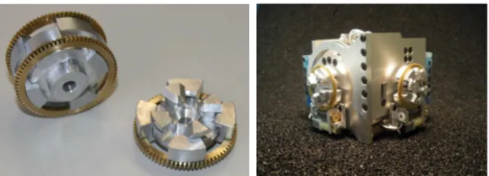
Fig. 3: A robot with four docking units
autonomous docking approach.
There have been a few studies made on autonomous docking for modular robots. The infra-red and vision based approaches are the most common methods used for the autonomous docking alignment. In CONRO project ([4], [5], [6]), a pair of IR transmitter and receiver are used to guide two CONRO snakes to sense the direction of each other. Although no orientation information can be obtained, they showed the snakes can successfully align and dock automatically. The IR-based approach has also been used in PolyBot project ([7], [8]), where 8 IR emitters and 4 receivers are used for 6 DOF offset estimation. To obtain the relative position and orientation between two docking surfaces, the robots need to be synchronised in advance and complicated measurement is required in real-time. Later on, Yim et al. [9] used vision-based localisation for autonomous docking. The LEDs on a module blink in a predefined way and can be recognised as a docking source by the on-board camera on another module. In their robots, magnets are used for the final alignment and docking. Murata [10] used vision-based algorithm to achieve docking for their M-TRAN robots, where videos are sent to a host PC for post processing via GHz radio transmission. As the visual feedback cannot provide sufficient position precision between the modules a specific docking configuration is necessary to absorb the position errors in the final phase of docking.
Autonomous docking has also been investigated in multi-ple mobile robotic systems, where vision-based approaches are mostly used to detect predefined target patterns. For example, Bererton et al. [11] used a black and white wireless camera to detect the visual target in another robot. The docking is completed by insert the forklift pins into the forklift receptacle on the other robot. However, the image is processed in a host PC instead of the robots. In Swarm-Bot project, each robot is equiped with an omni-directional camera, a ring of RGB LEDs and a gripper for self-assembly. 7 connection slots can be defined as between any two neighbouring LED locations and identified by the omni-directional camera. Robots can then move accordingly and attach to each other using the grippers. They showed different morphologies can be made in 2D planar configurations with such docking mechanism ([12], [13], [14]).
The above studies have all demonstrated successful au-tonomous docking under certain environmental conditions. It can be seen that the implementation of sensors depends much on the mechanical design of docking units and is limited by the space constraint, energy consumption budget and functionality requirement. As our robots have very com-pact cubic shapes and require four-sides identical docking capabilities, we adopt an IR approach benefiting from the small installation size, low power consumption and low cost of the IR sensors. In this paper, we present the hardware development of an IR sensor system for autonomous docking using minimum number of components. The rest of the paper is organised as follows: in section II, we first outline the general approach for the design of the sensor system and give the detailed design in following sub sections. In section
III, we show measurements from the sensors and examine their performance. In section IV, we conclude the paper.
II. THEAPPROACH
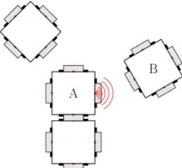
The general idea for the docking approach is illustrated in Figure 4: once one robot (A) in the swarm decides to initialise the docking process it will broadcast some signal to attract other robots. Another robot (B) within range can detect the signals using an array of sensors and move towards the signalling robot along the detected direction. Thus docking can be divided into three stages according to the range between A and B:
1) recruitment – B detects A’s ‘docking’ signal at long range but can only obtain approximate direction infor-mation;
2) docking alignment – B executes precise alignment at short range;
3) docking ready – A and B are close enough that the physical docking mechanism can take effect.
1 2
5 6
4 3
7 8
A
1 2
5 6
4 3
7 8
B
1 2
5
6 4 3
7 8
1 2
5
6 4 3
7 8
Fig. 4: Scenario for autonomous docking
To accomplish such a procedure, either sound or light signals can be used. However, considering the power consumption, the physical dimensions, the operational range and also the commercial availability of the sensors, we choose to use only Infra-Red signals in our implementation. Here we develop three different sensor units with different operational range for these purposes. The IR signals detected by the sensors are either actively emitted by other robots or emitted by the robot itself and reflected from another object. Table I lists the essential components used in our design against the proposed functions. We categorise the functionality of these sensor units to be obstacle detection (proximity sensor), beacon detection (docking sensor) and local communication, according to their operational range, which also correspond to stages 3, 2, 1 respectively. As each robot has a cubic shape (size:80×80×80mm) and docking is allowed on four sides, multiple identical sensors will be distributed around the robot, as shown in Figure 5. An 8-bit AVR micro-controller (Atmega1280 [15]) with ultra-low power consumption is used to control these sensors and communicate with upper MCUs via an I2
TCRT1010TSML1020 TCRT1010
TSML1020 TSML1020
TSOP36236 40mm
27mm 22mm
54mm (a)
7 6
4 5
0 1
3 2
(b)
Fig. 5: Placement of the sensors: (a) side view (b) top view
TABLE I: The usage of sensors against the functionality
Functions IR sensor
1
LED2 IR receiver3
emitter receiver
Proximity X X
Docking X X
Communication X X
1
TCRT1010;2TSML1020;3TSOP36236.
A. Obstacle Detection (Proximity sensor)
emitter
receiver TCRT1010
A/D GPIO
ATmega1280 AVR
Fig. 6: IR sensor detects object
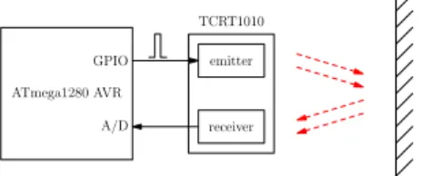
Obstacle detection plays two roles during the docking approach process: (1) detecting the obstacles when approach-ing the signallapproach-ing robots and (2) detectapproach-ing the distance to the signalling robots for docking alignment (with the beacon detection sensors introduced in the next section). As illustrated in Figure 5 (b), 8 IR sensors (TCRT1010) (marked with dark rectangles) are placed on the four side PCB boards, two on each side. The TCRT1010 are reflective sensors which include an infra-red emitter and a photo-transistor [16]. The output of the photo-transistor is connected to the A/D input of the ATmega1280 (see Figure 6). Given that the intensity of the received reflected light depends not only on the distance to the object but also on the material of its surface then, in order to gain better performance (longer detection range), the sensor has to be driven in its maximum current condition. However, under such conditions the sensor consumes a large amount of power if the emitter is turned on continuously (around 50 mA for each sensor). To reduce power consumption, the emitters of the TCRT1010 are controlled using 8 GPIO pins with a very low duty cycle pulse. Additionally, to minimise the interference between two close IR sensors, we must avoid turning them on at the same time. Thus each IR sensor is lit in sequence to meet this
12ms
96ms
Pulse0 Pulse1 Pulse2 Pulse3 Pulse4 Pulse5 Pulse6 Pulse7
Fig. 7: Timing diagram for the control pulse of the emitters
requirement. Figure 7 shows the timing diagram for these 8 control pulses. The width of each pulse is 350 µs. For each pulse, two readings are taken to sample the value of the reflected light sent out by the emitter: the first reading is taken just before the corresponding GPIO pin changes from low to high, which returns the intensity of the environmental ambient light, while the second is obtained before the control pin changes from high to low, which returns the intensity of both the reflected and environmental light. The reflected light can then be calculated from these two readings.
Each sensor is updated every 96 ms, which gives us an update rate of around 10 Hz. However, the update rate can be increased given different sets of control pulses. For instance, turning on 4 non-adjacent IR sensors simultaneously each time provides a 50 Hz update rate approximately. As the length of the A/D converters of ATmega1280 is 10-bit, the output values of the sensors lie between 0 and 1024 (the bigger the value, the closer the object to the sensor). However, it is unwise to rely heavily on the computed distance to the detected object because the value returned varies with the surface property, even at the same distance.
B. Beacon Detection (Docking Sensor)
Due to the unique design of the docking mechanism (see Figure 3), successful autonomous docking between two robots requires reasonable accuracy of alignment prior to docking. The idea to achieve the alignment is somewhat like beacon detection: one robot flashes an IR LED (TSML1020) at a fixed frequency - placed right above the docking unit - acting as a beacon, while the other robot uses its 8 IR sensors (the same ones used for obstacle detection) to detect the signals. To deal with the situation that the robot may turn 90◦in both directions, on each side PCB, two extra LEDs are
placed on both the left and right sides close to the docking units, as shown in Figure 5 (a). However, each time only one of them can be turned on to transmit the ‘docking’ signal which depends on the current pose of the robot. Figure 8 depicts the approach to detecting the beacon signals. The implementation for each block is explained next.
Sampling at
250Hz Digitial Filter Rolling Average
32Hz
TSML1020 TCRT1010
Sensor Data
96ms
2ms 4ms Pulse0 Sample
Fig. 9: Sampling timing of one TCRT1010 for both beacon detection and obstacle detection
1) Sampling: As IR sensors work for obstacle detection
and beacon detection simultaneously, the timing for sampling the analogue output of each TCRT1010 has to be carefully managed. Figure 9 shows the timing diagram for sampling one of the IR sensors. The LEDs are flashing at 32 Hz while sampling is at 250 Hz, both controlled by timer interrupt. The frequency of flashing the LEDs and sampling the ADC are carefully chosen by considering the performance of the digital filter and the specification of the Atmega1280 processor.
2) Digital Filter: With current settings, there are multiple
IR signals emitted by the robots which include 32 Hz ‘docking’ signals, 36 KHz ‘communication’ signals (which will be introduced later) and 10 Hz ‘obstacle detection’ low duty cycle signals. All of them can be picked up by IR sensors whenever they are in range. The environmental lighting, e.g lamp lights, sunshine also affect the output of the IR sensors. Among these signals, clearly only 32 Hz ‘docking’ signals are expected input signals for the beacon detection purpose. Although either hardware filter or digital filters can be used to exclude the noise signals. To simplify the design and also minimise the number of components for the implementation, here a 2nd-order fixed point IIR filter [17] is implemented in the ATmega1280 to filter out the environmental light noise, and also the light emitted by nearby robots (from TCRT1010 or RGB LEDs).
The digital filter algorithm is in fact a sum of products. When implementing a filter on a given MCU architecture, the resolution of input, output and the filter coefficient must be carefully considered. Since the ATmega1280 is an 8-bit architecture, it is very important to avoid overflow in fixed point algorithms. Overflow may occur at two places in the filter algorithm: in the sub-results of the algorithm and in the output of the filter. As the ADC output of ATmega1280 is 10-bit, a 16-bit integer variable is used to store the sample, so the resolution of input samples are 16-bit. According to [18], the required resolution of accumulator for the filter must satisfy the following condition:
N ≥2×K+logx(M) + 1 (1)
WhereNis the number of bits needed,Kis the bit resolution (excluding sign bit) of the input samples and coefficients, and M is the number of additions. For a 2nd-order IIR filter, to avoid overflow in the sub-results (accumulation), the minimal resolution of the accumulator is 34-bits when K= 15andM = 5. Hence, a 64-bit integer variable is used as accumulator.
Another important issue is the representation of the filter coefficients, although fractional multiplication is available,
integer multiplication can achieve much better performance (in speed) for fixed point architectures. For the purpose of using fractional filter coefficients in integer multiplications, we need to scale all the coefficients by the largest com-mon factor, in consequence, a downscaling of the output is necessary to get the correct value. It is well understood that the scaling factor should be of the form 2K
since division and multiplication by factors of 2 may easily be done with bitshifts. In our implementation, the scaling factor is set to 1024 (210
). Based on these considerations, an implementation of digital filter in Atmega1280 is given in the listing below.
Listing 1: C code for digital filter
# d e f i n e S 10 / / f i l t e r s c a l i n g
i n t 3 2 t a [ 3 ] ={1 0 2 4 , 1 3 2 1 , 903}; i n t 3 2 t b [ 3 ] ={6 1 , 0−61};
s t a t i c i n t 1 6 t f i l t e r I n [ NUM IR ] [ 3 ] ={0};
s t a t i c i n t 1 6 t f i l t e r O u t [ NUM IR ] [ 3 ] ={0};
i n t 6 4 t sum = 0 ;
i n t 1 6 t f i l t e r ( i n t 1 6 t i n d e x , i n t 1 6 t v a l u e )
{
sum = 0 ; / / 64 b i t s d a t a f o r a c c u m u l a t o r
/ / sub−r e s u l t s
f i l t e r I n [ i n d e x ] [ 2 ] = f i l t e r I n [ i n d e x ] [ 1 ] ; f i l t e r I n [ i n d e x ] [ 1 ] = f i l t e r I n [ i n d e x ] [ 0 ] ; f i l t e r I n [ i n d e x ] [ 0 ] = v a l u e ;
f i l t e r O u t [ i n d e x ] [ 2 ] = f i l t e r O u t [ i n d e x ] [ 1 ] ; f i l t e r O u t [ i n d e x ] [ 1 ] = f i l t e r O u t [ i n d e x ] [ 0 ] ;
sum = b [ 0 ]∗ f i l t e r I n [ i n d e x ] [ 0 ] + b [ 1 ]∗ f i l t e r I n [ i n d e x ] [ 1 ] + b [ 2 ]∗ f i l t e r I n [ i n d e x ] [ 2 ]−a [ 1 ]∗ f i l t e r O u t [ i n d e x ] [ 1 ]−
a [ 2 ]∗ f i l t e r O u t [ i n d e x ] [ 2 ] ;
/ / r e s c a l e
f i l t e r O u t [ i n d e x ] [ 0 ] = ( i n t 1 6 t ) ( sum>>S ) ;
r e t u r n f i l t e r O u t [ i n d e x ] [ 0 ] ;
}
3) Rolling Average: The output of the digital filter is a
stream of data at sampling rate 250 Hz (the same as the input of the digital filter), clearly it can not be used directly for docking alignment. Alternatively, a rolling average operation (i.e moving average filter) is applied to the output of the digital filter to obtain the relative strength of the detected ‘docking’ signals. The procedure can be imagined as a window of a certain size moving along the array, one element at a time. The output is the average of all elements in the window. Listing 2 gives an implementation of C code in the
ATmega1280. Since no hardware division is available in the
Atmega1280, a window size of the form 2K
proves to be computationally efficient as division can be achieved using bitshifts.
Note that the above three procedures are applied to each IR sensor individually. Using a ring of 8 sensors, the robot should have the ability to find the correct direction of the beacon and therefore perform the required alignment prior to mechanical docking.
C. Local IR Communication
Listing 2: C code for rolling average
# d e f i n e LENGTH 64
s t a t i c i n t 1 6 t v a l u e H i s t [ NUM IR ] [ LENGTH]={0};
s t a t i c ch a r v a l P o i n t e r [ NUM IR]={0};
s t a t i c i n t 3 2 t r e s u l t [ NUM IR]={0};
i n t 1 6 t r o l l i n g A v g ( i n t 1 6 t i n d e x , i n t 1 6 t v a l u e )
{
/ / g e t a b s o l u t e v a l u e
i n t 1 6 t a b s v a l u e = ( v a l u e<0 ) ?−v a l u e : v a l u e ;
/ / t h r o w away t h e o l d v a l u e and p u t t h e new o n e
r e s u l t [ i n d e x ] = r e s u l t [ i n d e x ]−v a l u e H i s t [ i n d e x ] [ v a l P o i n t e r [ i n d e x ] ] + a b s v a l u e ; v a l u e H i s t [ i n d e x ] [ v a l P o i n t e r [ i n d e x ] ] = a b s v a l u e ;
v a l P o i n t e r [ i n d e x ] + + ;
i f ( v a l P o i n t e r [ i n d e x ]>=LENGTH)
v a l P o i n t e r [ i n d e x ] = 0 ;
/ / a v e r a g e
r e t u r n ( i n t 1 6 t ) ( r e s u l t [ i n d e x ]>>6 ) ;
}
RX
TX UART
ATmega1280 AVR
Timer5 I2C
SCL SDA
74AHC08 74AHC04
TSML1020
RX
TX UART
ATmega1280 AVR
I2C
SCL SDA Cortex/Blackfin MCU
I2C
Cortex/Blackfin MCU
I2C
C
IR
C
U
IT
TSOP36236
robot1 robot2
Fig. 10: Local IR communication using the UART module
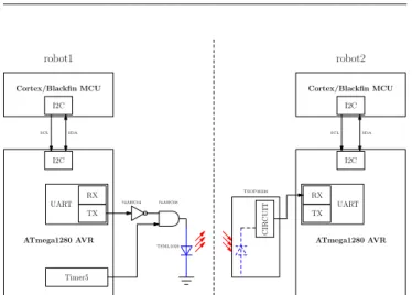
required to recruit more robots for the organism transform process. By adding four IR receiver modules (TSOP36236) into the existing sensor module, we can extend the IR signals to much longer range. The output of these IR receivers however are not value coupled with the relative intensity of the IR signals, but the information it transfers. The idea of the local IR communication is explained in Figure 10. The UART module of the ATmega1280 is used to avoid the need to develop new low level communication protocols. One IR LED (TSML1020), placed right above the docking unit which also acts as beacon for beacon detection, is controlled by the transmitter of the UART module to transmit the signals. A 36 Hz pulse signal is generated using timer 5 of the
ATmega1280. This carrier frequency is selected to match the
centre frequency of the bandpass of the TSOP36236 [20]. As the default output of the TSOP36236 is logical high (when no signals are detected), a logical inverter is added to the TX pin of the UART. The signals transmitted by the IR LED can be received and demodulated by an IR receiver module
TSOP36236. This configuration enables us to use the UART
module to send and receive messages directly.
To understand how the signals are transmitted and re-ceived, Figure 11 plots the signal timing for sending one byte (0x8C) via the transmitter of the UART. For each bit of the data, the TSOP36236 requires the burst length to be 10 cycles/burst or longer, therefore the baud rate of the UART
Timer 5
TX
start 1 0 0 0 1 0 1 0 stop
TSML1020
RX(TSOP36236)
Fig. 11: Timer 5 works at 36 Hz, baud rate 2400 for the UART module
module can be{300, 600, 1200, 2400}. Here 2400 is chosen for the best performance.
Clearly one TSML1020 can not emit signals omni-directionally, nor does the IR receiver, hence IR commu-nication is limited to a certain range and angle. The four UART modules in the ATmega1280 allow us to implement four different IR communication channels for each robot, one channel on each side. These four channels can work individually. As the receivers of UART modules operate in interrupt mode, by default, all four channels are in ‘listening’ mode. Whenever one robot is broadcasting messages, another robot within range will receive the message with one or two adjacent channels, which provides the robot with rough directional information about where the signalling robot is. However, as mentioned previously, the IR communication module shares one LED with the beacon detection module, thus the transmitter of the IR communication is not always available (i.e. the robot can not send messages using the channel when it is acting as a beacon).
III. RESULTS
Figure 12 is a picture of our first prototype of robot with all electronics and docking units integrated. All sensors described in this paper are distributed on the four side PCBs, including 8 IR sensors (TCRT1010), 12 IR LEDs (TSML1020) and 4 IR receivers (TSOP36236). To gain the best performance, they are placed exactly at the same place on each board as indicated in Figure5 (a). The following experiments were carried out to test the sensors.
Fig. 12: First prototype of a SYMBRION robot
1) Obstacle detection: Since the proximity sensor actively
robot1
1 2
5
6
4
3
7
8
(a)
0 100 200 300 400 500 600 700 800 900 1000
va
lu
e
20 40 60 80 100 120
distance(mm)
white cupboard
grey metal
(b)
Fig. 13: Output of IR sensor for obstacle detection: (a) movement of the robot – straight line (b) output of sensor against the distance to the object
light from the output of the photo-transistors, the output of sensors vary not only with the distance to the object, but also with the material of the surface. Figure 13 plots the data from one of the sensors. The robot is driven to move in a straight line both towards and away from an object, as shown in Figure13 (a). Two different materials (white cupboard and grey metal) are used to test the output of the sensor. Error bars show the standard deviation from 10 experimental runs. It is well known that the intensity of the light follows the inverse square law. Not surprisingly, the output of the sensor varies non-linearly with the distance to the object, the shorter the distance, the larger the value. Experiments suggest that the maximum detection distance for the proximity sensor is about 12 mm, with a value around 4 (maximum 1024).
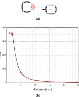
2) Beacon detection: Unlike the proximity sensor, the
docking sensor detects the signals emitted by the flashing LEDs. Hence the output of the sensor depends on both the distance and the angle it faces the beacon. As shown in Figure 14 and Figure 15, the robot is driven in two different ways to capture the output of the sensors. In the first case, the robot moves in a straight line towards and away from another robot; the centre of the sensor is facing directly toward the flashing LED. Experiments are repeated 10 times. In the second case, the two robots are aligned centre to centre 8 cm apart. The detecting robot performs a rotation behaviour for 4 circles (1440 degrees). Note that the robot with the flashing LED is static in both cases. Again, the output of the sensors against the distance shows a non-linear property because of the inverse square law. We observe the output of sensors changing rapidly when its facing angles changes. This is believed to be because: (1) the intensity changes proportionally with cosα, whereαis the facing angle; and (2) the non-uniform distribution of the relative intensity of the
robot1
1 2
5
6
4
3
7
8
robot2
1 2
5
6
4
3
7
8
(a)
0 100 200 300 400
va
lu
e
5 10 15 20 25
distance(cm)
(b)
Fig. 14: Beacon detection: (a) movement of the robot – straight line (b) output of sensor against the distance to the beacon
robot1
1 2
5
6
4
3
7
8
robot2
1 2
5
6
4
3
7
8
(a)
0 100 200
va
lu
e
0 300 600 900 1200
angle(◦) (b)
Fig. 15: Beacon detection: (a) movement of the robot – rotation (b) output of sensor against the angle the robot turns
light emitted by TSML1020 against the angular displacement (refer to [19] for details). Measurement from experiments provides evidence that the docking sensor can work in a range up to 25 cm.
0 100 200 300 400 500 600 700 800
va
lu
e
0 100 200 300 samples
(a) before filter, with lamp light off
0 100 200 300 400 500 600 700 800
va
lu
e
0 100 200 300 samples
(b) before filter, with lamp light on
−60
−50
−40
−30
−20
−10 0 10 20 30 40 50 60
va
lu
e
0 100 200 300 samples
filtered averaged
(c) after filter, with lamp light off
−60
−50
−40
−30
−20
−10 0 10 20 30 40 50 60
va
lu
e
0 100 200 300 samples
filtered averaged
(d) after filter, with lamp light on
Fig. 16: Output of docking sensors before and after filtering
0 20 40 60 80 100 120 140
0 0.1 0.2 0.3 0.4 0.5 0.6 0.7 0.8 0.9 1
FFT Power Spectrum
Frequency / Hz
Normalised Amplitude
(a) before filter, with lamp light off
0 20 40 60 80 100 120 140
0 0.1 0.2 0.3 0.4 0.5 0.6 0.7 0.8 0.9 1
FFT Power Spectrum
Frequency / Hz
Normalised Amplitude
(b) before filter, with lamp light on
0 20 40 60 80 100 120 140
0 0.1 0.2 0.3 0.4 0.5 0.6 0.7 0.8 0.9 1
FFT Power Spectrum
Frequency / Hz
Normalised Amplitude
(c) after filter, with lamp light off
0 20 40 60 80 100 120 140
0 0.1 0.2 0.3 0.4 0.5 0.6 0.7 0.8 0.9 1
FFT Power Spectrum
Frequency / Hz
Normalised Amplitude
(d) after filter, with lamp light on
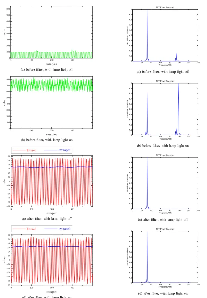
stronger IR radiation than that from the IR LEDs. When the lamp is turned on, a significant change in the values for the samples before the filter (or after ADC sampling) can be observed from Figure 16 (a) - (b). The normalised power spectrum tells us the signals are made up of signals at 32 Hz, 100 Hz and some harmonic frequency. However, after filtering, as we expected, only the signals at 32 Hz are left regardless the status of the lamp. From Figure 16 (c) - (d), we can see the output of the sensor (after rolling average) is very close in both cases. More specifically, the final output of the sensor is 34.06 with standard deviation 0.74 for the lamp-switched-off case and 32.53 with standard deviation 0.61 for the lamp-switched-on. It is clear that the digital filter works as expected and the docking sensors can pick up the beacon signal even in a noisy environment.
3) Local IR communication: The IR communication units
are also tested using two real robots. The experiments suggest the maximum communication distance can be up to about 1.5 metres. As the IR communication shares IR LEDs with beacon detection units, this range is adjustable for both units by tuning the transmission current supplied for the LEDs. The current settings are optimised based on the consideration of both performance and the power consumption.
IV. CONCLUSION
In this paper we have presented an approach and im-plementation using several IR sensor units to achieve au-tonomous docking for a swarm of self-assembling robots. The design utilises minimal components to achieve maxi-mum functionality in order to meet demanding constraints of both physical space and power consumption. The au-tonomous docking can be described as a ‘recruitment – docking alignment – docking ready’ procedure based on the proposed three sensor units. Of these sensors, the proximity sensors work also for general purpose short range obstacle detection, while the IR communication units will allow us to develop more complex communication protocols beyond simple message broadcasting in the future.
The design has been fully tested on real robotic platforms. Several experiments were designed to measure the real-time output of the sensors. The figures plotted and results obtained were used to guide the design of the controller. As we used a separate micro-controller for controlling and processing the sensors the implementation is relatively independent of the other modules in the overall design for the robot platform; the design could therefore be very easily transfered to other robotic platforms for general use.
At the time of writing the SYMBRION project is still at an early stage of development. As a very limited quantity of prototype robots have been built, we haven’t yet carried out thorough experiments to test autonomous docking in a multi-robot environment. However, we have successfully demonstrated the autonomous docking alignment using a very simple one layer artificial neural network controller with the sensors developed in this paper. A movie is available at http://www.brl.uwe.ac.uk/projects/symbrion/demo.html.
V. ACKNOWLEDGEMENTS
The “SYMBRION’ project is funded by the European Commission within the work programme Future and Emer-gent Technologies Proactive under grant agreement no. 216342. The authors would like to thank Jan Dyre Bjerknes of the Bristol Robotic Lab for his generous help when debugging the hardware.
REFERENCES
[1] http://www.swarm-bot.com, The Swarm-bots project. Accessed 11 May 2009.
[2] http://www.swarmanoid.com, The Swarmanoid project. Accessed 11 May 2009.
[3] S. Kernbach, E. Meister, O. Scholz, R. Humza, J. Liedke, L. Ricotti, J. Jemai, J. Havlik, and W. Liu, “Evolutionary robotics: The next-generation-platform for on-line and on-board artificial evolution,” in IEEE congress on Evolutionary Computation, Trondheim, Norway, May 2009.
[4] Wei-Min Shen and Peter Will. Docking in self-reconfigurable robots. pages 1049–1054, 2001.
[5] M. Rubenstein, K. Payne, P. Will, and Wei-Min Shen. Docking among independent and autonomous conro self-reconfigurable robots. In Robotics and Automation, 2004. Proceedings. ICRA ’04. 2004 IEEE International Conference on, volume 3, pages 2877–2882 Vol.3, April-1 May 2004.
[6] Kenneth Payne, Jacob Everist, Feili Hou, and Wei-Min Shen. Single-sensor probabilistic localization on the SeReS self-reconfigurable robot. In The 9th Intl. Conf. Intelligent and Autonomous Systems (IAS-9), Tokyo, Japan, March 2006.
[7] Kimon Roufas, Ying Zhang, Dave Duff, and Mark Yim. Six degree of freedom sensing for docking using ir led emitters and receivers. In ISER ’00: Experimental Robotics VII, pages 91–100, London, UK, 2001. Springer-Verlag.
[8] M. Yim, Ying Zhang, K. Roufas, D. Duff, and C. Eldershaw. Con-necting and disconCon-necting for chain self-reconfiguration with polybot. Mechatronics, IEEE/ASME Transactions on, 7(4):442–451, Dec. 2002. [9] M. Yim, B. Shirmohammadi, J. Sastra, M. Park, M. Dugan, and C.J. Taylor. Towards robotic self-reassembly after explosion. In Intelligent Robots and Systems, 2007. IROS 2007. IEEE/RSJ International Con-ference on, pages 2767–2772, 29 2007-Nov. 2 2007.
[10] S. Murata, K. Kakomura, and H. Kurokawa. Docking experiments of a modular robot by visual feedback. In Intelligent Robots and Systems, 2006 IEEE/RSJ International Conference on, pages 625–630, Oct. 2006. [11] Curt Bererton and Pradeep Khosla. Towards a team of robots with
repair capabilities: A visual docking system, 2001.
[12] Roderich Gross, Michael Bonani, Francesco Mondada, , and Marco Dorigo. Autonomous self-assembly in swarm-bots. IEEE TRANSAC-TIONS ON ROBOTICS, 22(6):1115–1130, 2006.
[13] R. Gross and M. Dorigo. Self-assembly at the macroscopic scale. Proceedings of the IEEE, 96(9):1490–1508, Sept. 2008.
[14] Anders Christensen, Rehan O’Grady, and Marco Dorigo. Swarmorph-script: a language for arbitrary morphology generation in self-assembling robots. Swarm Intelligence, 2(2):143–165, December 2008. [15] ATMEL, “Datasheet of ATmega1280,” August 2007.
[16] Vishay Semiconductors, “Datasheet of TCRT1000/TCRT1010,” September 2006.
[17] S. J. Orfanidis, Introduction to Signal Processing. Prentice Hall, 1999.
[18] ATMEL, “AVR223: Digital filters with AVR,” July 2008.
[19] Vishay Semiconductors, “High power infrared emitting diode, TSML1000/1020/1030/1040,” March 2005.