Manipulating Objects with Gliders in Cellular Automata
Ioannis Georgilas*, Andrew Adamatzky and Chris Melhuish
Abstract— Micro-scale manipulation of objects is a growing requirement in specialised industries, especially those related to assembly of fragile micro-components. Widely implemented techniques in robotics and automation do not always cope with the delicate nature of the process. To improve the micro-scale manipulators we consider both hardware and software issues, and focus on designing massive-parallel embedded controllers for non-trivial actuating surfaces.
This paper offers an initial insight on cellular automata (CA) gliders control of a smart surface. A brief presentation of the prototype hardware will be given along with a justification on the selection of manipulated objects. The formulation of the excitable CA lattice is presented and experimental data is anal-ysed. The results support the capabilities of a fully distributed CA controlled massive parallel manipulation architecture.
I. INTRODUCTION
Manipulation of parts in micro-assembly proves to be a demanding application that classic robotics and automation methods struggle to achieve. The requirements of these applications is precision, optimum force utilisation, non-prehensile handling in most applications and multiple parts being manipulated during a given work cycle. Because of these requirements issues for the scalability of the system arise and computational bottlenecks manifest. Also, generat-ing lateral forces in an efficient manner is troublgenerat-ing. As a result, in the physical layer (hardware), massive parallelism and a distributed architecture is required while in the control layer (software) novel, decentralised intelligent strategies must be utilised.
A promising solution to the specialised hardware require-ments of micro-assembly is the implementation of parallel manipulators in a surface-like design [1]. These systems consist of a massive array of simple actuators (with a small power density) that collectively transport, orient and position objects whose masses and sizes are very high compared to the forces generated by a single actuator. Each individual actuator is relatively inexpensive, and a modular structure of the parallel manipulator allows for mass production and scalability. Approaches to implement such systems include airjets [2], [3], [4], mechanical wheel based arrangements [5], [6], sound based solutions [7] and electromechanical ac-tuators to excite membranes [8], [9]. Similar solutions are followed in micro-scale with micro electro-mechanical sys-tems (MEMS) [10], [11] where the surface is fabricated using silicon integrated circuits (IC) technology. Examples
This work was supported by Engineering and Physical Sciences Research Council (EPSRC), grant reference EP/H023631/1.
I. Georgilas, A. Adamatzky and C. Melhuish are with the Bristol Robotics Laboratory and the Unconventional Computing Centre, University of the West of England, Bristol
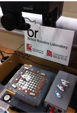
[image:1.612.353.518.147.388.2]*corresponding [email protected]
Fig. 1. The prototype system. The toothbrush heads, the 8×8 cell array and the vision feedback camera is visible.
of natural parallel manipulators include the cilia arrays in paramecium which generates coherent propulsive forces and the sea urchins tube feet which allow for locomotion and object transfer.
In the control layer spatially distributed excitable media, namely Cellular Automata (CA), prove to be viable candi-dates due to there inherent processing abilities. Research examples exist for emergent computational architectures employing nature-inspired information processing based on massive distribution of workload using excitable media. Algorithms and techniques of information processing, based on the interaction of excitation wave-fronts, have already found their application in control of robot navigation [12], [13], [14].
replicate ciliary motions to displace objects. As manipulated objects we are using toothbrush heads. This decision was taken to exploit their special attributes on force distribution and redirection. We will show that by implementing proper CA patterns a toothbrush head can glide towards a predefined target destination.
Toothbrush heads are being used to demonstrate the poten-tials of the system. They are the initial step to understand the dynamic of the CA controlled smart surface and establish an initial model. Based on the results of the current work general control techniques can be developed for the manipulation of generic shape objects.
The structure of the paper is as follows. First, in section II a description of the hardware will be given for both the smart surface and the special geometry of toothbrush heads. In section III the CA algorithm to generate the gliders, the feedback loop and the decision process will be analysed. In section IV experimental data of the motion of toothbrushes under the effect of gliders will be given along with the analysis and discussion of the results.
II. THEHARDWARE
A. Components of the Smart Surface
During the development of the prototype a layered mod-ular architecture has been selected, Fig. 2(a). The smart surface consists of multiple smaller modules that connect seamlessly among each other. Each module is divided into two layers, mechanical and electronics. The mechanical layer consists of four components, epidermis, vibrators, substrate and support mesh, while in the electronics layer there are three boards, motor controllers, sensors and processing.
The first part of the mechanical layer, epidermis, Fig. 2(a)i, covers the top of the smart surface (multiple modules) im-proving seamless integration. Two are the main functions of epidermis. Firstly, it operates as a gripping surface to transfer the forces from the vibrating motors to the toothbrush. This is achieved by the friction between the silicon material of the membrane and the material of the toothbrush’s hairs. Secondly, acts as a loose mechanical coupling between the oscillating vibrating motors.
The vibrators, Fig. 2(a)ii, are the actuators of the system. They are round, flat, core-less vibration motors generating 1.2G amplitude of vibration. The forces are generated radi-ally by a rotating eccentric mass in a XY plane. Because of the smooth metallic surface of the motors and the sealed motor’s case any alterations are not possible. As a result, the motors are connected to the silicon membrane using the gripping effect of the latter and to the substrate with adhesive material.
The flexible substrate, Fig. 2(a)iii, is the part of the system that the motors and the sensors are mechanically positioned. It is casted from silicon material and has a special shape consisting of platforms and openings. Each motor is placed on one of the platforms allowing it to freely move in the XY plane and also, because of substrate’s elasticity, slightly on the Z axis. Because of the rubbery nature of the material the vibrations are absorbed and do not affect adjacent motors.
!
!!
!!!
!"
!
(a) Module Layers
A AA
A AA
A AA
A AA
A AA
A AA
A AA
(b) Toothbrush Side View
[image:2.612.318.552.55.247.2](c) Toothbrush Front View
Fig. 2. Hardware Designs
The forth component, Fig. 2(a)iv, provides support for the previous elements of the mechanical layer. It is made out of ABS material to be robust and resembles a grid shape. It is gridded in order to allow passing of the sensors and power channels for the motors.
B. Sensory Feedback
The smart surface design includes a novel method for sensing the existence of objects and alter its operation. An array of photo sensors, Fig. 2(a)v, located in the space between the motors is triggered by the shadow casted from the objects. Using triangulation, the shape of the object can be assessed and the behaviour of the control algorithm affected. This system can extract not only the location but also the orientation of the object.
C. Toothbrush Geometry
Due to the good energy manipulation, their geometry provide, toothbrush heads are being used for the experiments. The hairs of the toothbrush act as multiple points of contact, averaging the forces by the motors. Moreover, the slopped structure of the hairs, Fig. 2(b), generate a clear vector of energy transfer that creates a distinctive front side of the toothbrush (arrow in the figure). Finally, the overall geometry of the toothbrush, resembling a bathtub, Fig. 2(c), implemented for better hygiene results in teeth brushing, create contact points for force differentiation. This particular characteristic is being exploited to rotate the toothbrush by applying specific pattern of forces.
III. THECONTROLLER
A. CA Algorithm
Cellular automaton (CA) is an array of locally connected finite state machines (called cells), which takes finite number of states and update their states simultaneously by the same
cell-state transition function. Each cellxupdates its state
de-pending on states of its closest neighboursu(x) ={y6=x:
|x−y|L∞ = 1}. We have chosen2
+-medium CA [16], [12]
as an embedded controller of the smart surface. Each cellx
i i i i i i i i i i i i i i i i
+ +
−
− ⇒
i i i i i i i i i i i i i i i i
+ +
−
− ⇒
i i i i i i i i i i i i i i i i + +
−
− →
Fig. 3. Typical travelling localisation in2+-medium [12].
A resting cell becomes excited if the number of excited neighbours is exactly two. An excited cell takes refractory state, and refractory cell takes resting state unconditionally.
We define a two-dimensional lattice Aof cells, where each
cellxtakes one of three states: resting (·), excited (+) and
refractory (−), and updates its statextby the rules in (1).
xt+1=
+, xt=·and P
y∈u(x)χ(y,+) = 2
−, xt= +
·, otherwise
(1)
whereχ(y,+) = 1if y= +and 0, otherwise.
Amongst many intriguing propagating patterns 2+
-medium exhibits discrete analogs of dissipating solitons, particles or gliders, propagating along rows and columns, and
along diagonals of the CA array (Fig. 3). The 2+-medium
is a deterministic automaton, therefore the particles keep their shapes indefinitely unless disturbed or reach absorbing boundaries of the array. For the purpose of manipulation we are using the minimal travelling localisation, or glider,
so-called2+-particle (Fig. 3a). This particles propagate strictly
in horizontal or vertical directions. They are like wave-fragments in a sub-excitable medium [14]: they have excita-tion wave-front, consisting of two states ’+’ and refractory tail, consisting of two ’-’ states.
B. Actuation Scheme
The states of the CA medium must be appropriately mapped to actual commands for the actuators. The mechani-cal layer, as described in previous chapter, consist of motors that apparently can have three states, rotating clockwise, rotating counter-clockwise and turned off. A mapping to connect the CA state as defined in (1) to actual motor states is arbitrarily selected and given in (2).
+
− ·
CW CCW
Of f
(2)
C. Vision Feedback - Target Selection
In order to reduce the complexity, the array of photo-sensors is simulated by a vision system. With this approach the focus is on the decision process and not on the quality of feedback, which is beyond the interest of the present re-search. A dedicated image recognition module continuously (30fps) analyse the location of the toothbrush and feeds the information to the decision module.
The information extracted for the toothbrush is the location of the front and the back, as described in section II-C. From those two points the orientation of the toothbrush on the plane of the surface is being calculated.
-6
y
x
q q
q
B
B’
T
yB
xB
yT
xT
φT
[image:3.612.369.504.50.182.2]φB
Fig. 4. Coordinates of Toothbrush head and Target.
q q
q q
q q
qC(0,0) qC(1,0)
C(0,1) C(1,1)
G(0,0) G(1,0)
G(0,1) G(1,1)
Fig. 5. Frames of reference for CA, C, and toothbrush and target, G.
The location of the target is being selected from the user in an on-screen interface resembling the smart surface. From the relevant location of the toothbrush’s front and the target, the orientation of the latter is being calculated. The toothbrush and the target position and orientation are given in (3) as
vectors B~ and T~ respectively, while a third vector can be
defined as there difference∆~ and illustrated in Fig. 4.
B=
xB
yB
φB
T =
xT
yT
φT
∆ =B−T =
∆x
∆y
∆φ
(3)
The elements of vectors B~ and T~ are real numbers and
their accuracy depends on the vision module. A process of discretizing those values is performed in order to create the feedback lattice. A lattice structure is implemented for two reasons; first to emulate the photo-sensors and secondly to
simplify CA rules generation. The lattice,G, is overlaid to
latticeC of the CAs.Gis transposed in relation to frameC
by1/2units of the latter, as depicted in Fig. 5.
D. Decision Algorithm
The decision algorithm, as a flow chart in Fig. 6, is performed iteratively accessing the data from the vision system and implement the necessary changes, as a CA matrix
St, or apply the normal CA update to the prototype.
Initially the orientation of the toothbrush, in regard to the target, is calculated and compared with a predefined range
[r1, r2]. If the angle ∆φ is outside this range a correction
pattern will be applied around the toothbrush trying to align the toothbrush and the target. The shape of the pattern
depends on the sign of∆φ. If the correction pattern must be
Apply theStor the new CA matrix
Toothbrush Position Update
Is∆φ∈[r1, r2]? St =
sign(∆φ)
0 1
+ −
− +
− +
+ −
Calculate Movement(4)Mt
IsMt=Mt−1? St=
∆y >∆x ∆y≤∆x
sig
n
(∆
y
)
/
sig
n
(∆
x
)
1
+ +
− −
− +
− +
-1
− −
+ +
+ −
+ −
Normal CA update No
Yes
[image:4.612.67.546.54.364.2]No Yes
Fig. 6. Decision process flowchart
integrated to the CA lattice at the location of the toothbrush, is mapped to the prototype.
If the orientation of the toothbrush is within limits, a minimum distance from target in X and Y axis is calcu-lated. Given the minimum of the two distances a movement direction index is computed according to (4).
Mt=
1,
if ∆y >∆xand sign(∆y) = 1
2, sign(∆y) =−1
3,
if ∆y≤∆xand sign(∆x) = 1
4, sign(∆x) =−1
(4)
wheresing(x) =
(−1, x <0
0, x= 0 1, x >0
The current movement direction index is compared to the index of the previous computation cycle and if the calculated index has changed a new CA pattern is selected. The selection criteria can be seen in the table at Fig. 6. As with the rotation pattern, no further calculation is performed and the pattern is mapped to the hardware.
If no pattern is being selected, because of the change in the orientation or movement direction, the normal CA update rules are being implemented. The updated state of the CA lattice is then being mapped to the hardware.
IV. EXPERIMENTS
A. System Setup and Collected Data
Evaluation of the described algorithm for the CA con-troller has been performed on the prototype system seen
in Fig. 1. The size of the surface is 110mm×110mm and
the size of the toothbrush head is 35mm×12mm. The
over-head vision feedback camera was positioned on a calibrated support to ensure parallelism between the camera and the prototype.
Two sets of experiments have been contacted. The first contains linear motion of the toothbrush, (the target is in the same line as the toothbrush‘s initial position). In the second set, change of direction path is necessary (the target
is positioned at a 90o angle from the line of direction of
the toothbrush). Two motions were recorded for each set. In Fig. 7(a) and Fig. 8(a) the overlap of the trajectories, with rotation as vectors, can be seen along with the start position of the toothbrush and the target. In Fig. 7(b) and Fig. 8(b) the trajectory and rotation of toothbrush body is separately plotted for ease of analysis.
B. Result Analysis
[image:4.612.57.299.513.611.2]0 50 100 150 200 250 300 350 0
50 100 150 200 250 300 350
X Coordinate (pixels)
Y Coordinate (pixels)
Movement 1 Movement 2 Starting Point Target
(a) Motion Vectors, Starting Point and Target
0 50 100 150 200 250 300 350 0
50 100 150 200 250 300 350
X Coordinate (pixels)
Movement 1
Y Coordinate (pixels)
Trajectory
0 20 40 60 80
−20 −10 0 10 20 30
Iteration
Angle (degrees)
Rotation
0 50 100 150 200 250 300 350 0
50 100 150 200 250 300 350
X Coordinate (pixels)
Movement 2
Y Coordinate (pixels)
0 20 40 60 80
−20 −10 0 10 20 30
Iteration
Angle (degrees)
[image:5.612.91.265.49.397.2](b) Trajectory and Rotation Data
Fig. 7. Set of Linear Movements
1) Linear Movements. (Fig. 7)
a) Between X coordinates 83 and 209. There are similar fluctuations in the trajectories followed. It can be noted that there is a twist to the left with the vectors facing to the right of the motion. b) At points (245, 183) and (265, 165). There are
two consecutive corners, the first to the right, followed by a left one. In both cases the right corner was sharp and the recovery at the second was progressive.
c) Rotation pattern after 40 iterations. Both movements exhibit the same rotation pattern. It is characterised by progressive increase in angle with a sudden spike, and consecutive diving, at around 50 iterations. Although the values of the fluctuations are different the final orientation is
around 25.5o, ”pointing” to the target.
2) Corner Movements. (Fig. 8)
a) Straight part. It can be observed that both movements exhibit the same oscillatory motion towards the right. There is an initial dive at iterations 5 and 7 respectively with a recovery pattern towards the cornering action.
b) Turning at 90o angle pattern. The progress of
the turning action is similar but not the same.
0 50 100 150 200 250 300 350 0
50 100 150 200 250 300 350
X Coordinate (pixels)
Y Coordinate (pixels)
Movement 1 Movement 2 Starting Point Target
(a) Motion Vectors, Starting Point and Target
0 50 100 150 200 250 300 350 0
50 100 150 200 250 300 350
X Coordinate (pixels)
Movement 1
Y Coordinate (pixels)
Trajectory
0 10 20 30 40 50 60 70 −120
−100 −80 −60 −40 −20 0
Iteration
Angle (degrees)
Rotation
0 50 100 150 200 250 300 350 0
50 100 150 200 250 300 350
X Coordinate (pixels)
Movement 2
Y Coordinate (pixels)
0 10 20 30 40 50 60 70 −120
−100 −80 −60 −40 −20 0
Iteration
Angle (degrees)
(b) Trajectory and Rotation Data
Fig. 8. Set of Corner (90o) Movements
Movement 1 executes a slower/longer turning circle expanding 26 iterations. Movement 2 is cornering in less time within only 16 iterations. What is interesting is that in +10 iterations from the initiation of the turning action, there is a
distortion of the rotation (iterations 35±2, 45±2).
c) Final orientation.Both movements have similar orientation in the end of there respective
trajec-tory. In both cases it is69o with the toothbrush
pointing towards the target.
Based on the above observations we can summarise the underlying reasons for the patterns to three different types.
Drifting movement of the toothbrush. The toothbrush head, because of the special geometry described in section II-C, tends to move in a drifting fashion, oscillating from side to side. This behaviour results in the observation 1a and partially in 1c and 2a.
[image:5.612.354.525.52.402.2]Algorithm and CA propagation.The implementation of the algorithm affects operations in two distinctive ways. First, the decision process, as described in III-D, affects the motion as an attempt to alter orientation of the toothbrush in respect to the distance from the target. This behaviour is obvious in cases 1c and 2c with the toothbrush trying to face the target in the final steps of the motion. Secondly, the CA glider propagation interval (200ms in the experiments) affects movement patterns. The most prominent example of this is in case 2b where the toothbrush seizes to move waiting for the glider to come again to continue. It is also partially responsible for 1b as the glider forces the toothbrush to turn sharply and continue movement with a new orientation.
C. Discussion
The different reasons for the patterns recognised in the experiments, allow to draw some interesting experience regarding the system both in hardware and software terms. The first two, drifting movement/motor variations, are related to the hardware being used, toothbrush head geometry and prototype variations. In order to emphasise the robustness of the proposed conveyor system the decision was taken to accept mechanical variations within specific tolerances. This way the system proves that it can compensate for those variations using the intelligent underlying control algorithm. Nonetheless, due to the systemic appearance of both issues, it is possible to map those mechanical imperfections and incorporate them in the controller.
The third reason is related to the implementation of the CA based control algorithm. Simple linear gliders in 2+ mediums seem to provide good linear object propagation while the proposed turning patterns address to a certain degree the
90◦ turns required for the selected trajectories. Both the
gliding and the turning patterns where selected from a pool of possible CA rule sets, due to their performance in following simple trajectories as the ones in Fig. 7 and 8. Furthermore, they perform satisfactorily in compensating for the hardware systems weaknesses. Undoubtedly, determining the iteration (generation) step is a crucial parameter affected by the dynamics of the system. Based on the observations from the current experiments improvements for the CA patterns can be developed as is the size and the speed of the gliders and the shape of the rotation pattern to create sharper cornering.
V. CONCLUSIONS
With the current work a smart surface based on small vibrating motors and controlled by Cellular Automata (CA) was presented. By using gliders, a phenomenologically non-dissolving CA pattern, we showed that an object can be transported towards a predefined target. Also, by including a
cornering CA pattern the object can corner at90◦angles. We
selected as objects toothbrush heads based on there geometry that provides a good energy manipulation behaviour. The CA control algorithm was described and experimental data was given. The system performed according to predictions with small variations from the intended operation, giving sound evidence of the universality of glider based transportation
in 2+ medium arbitrarily for translation and rotation of
objects. Furthermore, by using toothbrush heads, an easier to manipulate object compared to generic ones, we acquired an understand and predict the dynamics of the systems.
The analysis of the experimental data assisted in under-tanding the underlying phenomena both for the hardware and the software and design improvements. Based on the system-atic nature of hardware irregularities a mapping process to identify local phenomena can be developed. Systematising this data and incorporating it into the controller of the system can greatly improve performance since hardware variations can be addressed before the object reaches the areas in question. Regarding the CA controller, further investigation
and analysis of different2+medium rule sets can determine
the optimal setup, along with the iteration step for which the dynamics of the object being manipulated must be taken into consideration. Those improvements will enable the CA controller to control not only generic objects but also multiple at the same time, a goal for future research.
REFERENCES
[1] K.-F. Bohringer, B. R. Donald, R. Mihailovich, and N. C. MacDonald, “Theory of manipulation and control for microfabricated actuator arrays,” in Proc. IEEE Micr. Elect., (Oiso, Jpn), pp. 102–107, Publ by IEEE, 1994.
[2] H. Moon and J. Luntz, “Distributed manipulation of flat objects with two airflow sinks,”IEEE Trans. Robotics, vol. 22, no. 6, pp. 1189– 1201, 2006.
[3] K. Boutoustous, G. Laurent, E. Dedu, L. Matignon, J. Bourgeois, and N. Le Fort-Piat, “Distributed control architecture for smart surfaces,” in2010 IEEE/RSJ Int. Conf. Intelligent Robots and Systems, IROS’10, (Taipei), pp. 2018–2024, 2010.
[4] A. Delettre, G. Laurent, and N. Le Fort-Piat, “2-dof contactless distributed manipulation using superposition of induced air flows,” in
2011 IEEE/RSJ Int. Conf. Intelligent Robots and Systems, IROS’11, (San Francisco, CA), pp. 5121–5126, 2011.
[5] J. Luntz, W. Messner, and H. Choset, “Distributed manipulation using discrete actuator arrays,”Int. J. Rob. Res., vol. 20, no. 7, pp. 553–583, 2001.
[6] T. Murphey and J. Burdick, “Feedback control methods for distributed manipulation systems that involve mechanical contacts,”Int. J. Rob. Res., vol. 23, no. 7-8, pp. 763–781, 2004.
[7] T. Vose, P. Umbanhowar, and K. Lynch, “Vibration-induced frictional force fields on a rigid plate,” in2007 IEEE Int. Conf. Robot, ICRA’07, (Rome), pp. 660–667, 2007.
[8] K. F. Bohringer, V. Bhatt, B. Donald, and K. Goldberg, “Algorithms for sensorless manipulation using a vibrating surface,”Algorithmica (New York), vol. 26, no. 3-4, pp. 389–429, 2000.
[9] E. Setter and I. Bucher, “Flexural vibration patterning using an array of actuators,”J. Sound. Vib., vol. 330, no. 6, pp. 1121–1140, 2011. [10] M. Ataka, B. Legrand, L. Buchaillot, D. Collard, and H. Fujita,
“Design, fabrication, and operation of two-dimensional conveyance system with ciliary actuator arrays,”IEEE ASME Trans. Mechatronics, vol. 14, no. 1, pp. 119–125, 2009.
[11] H. Fujita and M. Ataka, “System configuration and fabrication technol-ogy for distributed mems,” in1st Worksh. Hardw. Softw. Impl. Contr. Distr. MEMS, dMEMS’10, (Besancon), pp. 1–5, 2010.
[12] A. Adamatzky,Computing in non-linear media and automata collec-tives. Institute of Physics Publishing, 2001.
[13] A. Adamatzky, B. De Lacy Costello, C. Melhuish, and N. Ratcliffe, “Experimental reaction-diffusion chemical processors for robot path planning,”J. Intel. Robot Syst, vol. 37, no. 3, pp. 233–249, 2003. [14] A. Adamatzky, B. D. L. Costello, and T. Asai, Reaction-diffusion
computers. Elsevier, 2005.
[15] A. Adamatzky and C. Melhuish, “Phototaxis of mobile excitable lattices,”Chaos. Soliton. Fract., vol. 13, no. 1, pp. 171–184, 2002. [16] A. Adamatzky,Identification of cellular automata. Taylor & Francis,