DOI 10.1007/s11548-016-1418-z O R I G I NA L A RT I C L E
Navigation system for robot-assisted intra-articular lower-limb
fracture surgery
Giulio Dagnino1 · Ioannis Georgilas1 · Paul Köhler1 · Samir Morad1 · Roger Atkins2 · Sanja Dogramadzi1
Received: 13 January 2016 / Accepted: 9 May 2016 / Published online: 28 May 2016 © The Author(s) 2016. This article is published with open access at Springerlink.com
Abstract
Purpose In the surgical treatment for lower-leg intra-articular fractures, the fragments have to be positioned and aligned to reconstruct the fractured bone as precisely as pos-sible, to allow the joint to function correctly again. Standard procedures use 2D radiographs to estimate the desired reduc-tion posireduc-tion of bone fragments. However, optimal correcreduc-tion in a 3D space requires 3D imaging. This paper introduces a new navigation system that uses pre-operative planning based on 3D CT data and intra-operative 3D guidance to virtually reduce lower-limb intra-articular fractures. Physical reduc-tion in the fractures is then performed by our robotic system based on the virtual reduction.
Methods 3D models of bone fragments are segmented from CT scan. Fragments are pre-operatively visualized on the screen and virtually manipulated by the surgeon through a dedicated GUI to achieve the virtual reduction in the fracture. Intra-operatively, the actual position of the bone fragments is provided by an optical tracker enabling real-time 3D guid-ance. The motion commands for the robot connected to the bone fragment are generated, and the fracture physically reduced based on the surgeon’s virtual reduction. To test the system, four femur models were fractured to obtain four different distal femur fracture types. Each one of them was
Electronic supplementary material The online version of this article (doi:10.1007/s11548-016-1418-z) contains supplementary material, which is available to authorized users.
B
Giulio Dagninogiulio.dagnino@uwe.ac.uk
1 Bristol Robotics Laboratory, University of the West of England, Coldharbour Lane, Bristol BS16 1QY, UK 2 Bristol Royal Infirmary, Upper Maudlin Street, Bristol
BS2 8HW, UK
subsequently reduced 20 times by a surgeon using our sys-tem.
Results The navigation system allowed an orthopaedic sur-geon to virtually reduce the fracture with a maximum residual positioning error of 0.95±0.3 mm (translational) and 1.4◦± 0.5◦(rotational). Correspondent physical reductions resulted in an accuracy of 1.03±0.2 mm and 1.56◦±0.1◦, when the robot reduced the fracture.
Conclusions Experimental outcome demonstrates the accu-racy and effectiveness of the proposed navigation system, presenting a fracture reduction accuracy of about 1 mm and 1.5◦, and meeting the clinical requirements for distal femur fracture reduction procedures.
Keywords Medical robotics·Fracture surgery· Computer-assisted surgery ·Fracture reduction planning·Image guidance·3D medical imaging
Introduction
In the surgical treatment for lower-leg intra-articular frac-tures, the fragments have to be positioned and aligned to reconstruct the fractured bone as precisely as possible (anatomical reduction) [1], to allow the joint to function correctly again [2], avoiding post-operative chronic pain, a reduced functioning of the limb, arthritis, and as a conse-quence, potential (partial) disablement [3,4].
risk of infection, with consequent prolonged hospitalization, rehabilitation time, and health-related costs [6,7]. Minimally invasive surgical techniques (i.e. percutaneous) have been developed to mitigate the problems related with open surgery. These techniques involve fragment manipulation using pins inserted in the fragments through small incisions in the patient’s flesh. Such techniques are associated with a faster recovery and a lower risk of infection compared to open surgery techniques [8]. However, the major challenge in min-imally invasive fracture surgery (MIFS) using the current surgical set-up is to deduce the desired reduction position of bone fragments from multiple intra-operative fluoroscopic images of the fracture. The 2D nature of these images, the localized and limited 2D field of view, and their low res-olution do not provide enough information to the surgeon in respect of the fracture alignment and rotation—which is essentially a three-dimensional problem—possibly causing a misinterpretation of the corrective parameters. In fact, opti-mal pose correction of the articular surface in 3D requires restoring six parameters: three translations and three rota-tions [3]. Also, the high forces occurring during the reduction process increase the physical load on the surgeon preventing the reduction movements [9] and occasionally resulting in suboptimal fracture reduction [6].
Image guidance and planning, together with robotic assis-tance, can actually have a positive impact in overcoming the issues identified above, through enhanced 3D medical imag-ing and increased positionimag-ing accuracy.
In this field, several studies have been carried out for long bone fracture reduction (specifically, femur shaft fractures) using 3D imaging. Joskowicz et al. [10] presented FRACAS, a computer-aided system that provides image guidance to the orthopaedic surgeon while reducing and fixing a long bone fracture. Fluoroscopic images are used to register pre-operative CT data to the intra-pre-operative imaging. Warisawa et al. [11] developed a robotic system for femur fracture reduction, based on the orthopaedic traction table design (i.e. an operating table, which allows the application of a constant and adjustable pull [12]), using 3D CT image mod-elling for reduction path generation. Westphal et al. [13,14] reported a robotic system for the reduction in femur shaft fractures based on a telemanipulated industrial serial robot. The surgeon controls the telemanipulated system from a console equipped with a joystick with force feedback to manipulate bone fragment attached to the robotic system based on 3D imaging data generated by intra-operative 3D fluoroscope. Tang et al. [15] and Graham et al. [16] uti-lized a parallel robot for the reduction in diaphyseal femur fractures based on 3D CT image reconstruction process for pre-operative planning. Buschbaum et al. [9] developed a sys-tem for computer-assisted repositioning of femoral fractures using 3D CT images. The system automatically generates the trajectories for reducing the fracture based on the
com-puted surface curvature and fracture lines. In addition, a variety of computer-aided navigation systems using 2D flu-oroscopic imaging were developed with the purpose of improving the reduction accuracy, such as [17–19]. How-ever, all the described systems are restricted to long bone fractures, attempting to solve a different problem from intra-articular fractures that involve joints and typically require higher reduction accuracy [20]. Long bone fractures have smaller number of larger fragments that present a 2D prob-lem for surgical reduction and are perceived easier to manage in the clinical setting using the current 2D imaging systems (fluoroscope). Intra-articular fractures are 3D fractures and are, therefore, more difficult to solve using 2D intra-operative images. Although some systems for fracture reduction based on 3D imaging are reported in the literature [9–11,13–16,21], their use has been limited to reduction in long bone fractures. To the best of our knowledge, no computer-assisted robotic system for intra-articular fracture reduction has been reported in the literature.
Robot-assisted fracture surgery (RAFS) is the focus of new research at Bristol Robotics Laboratory (BRL). Raabe et al. [22] developed the first robotic prototype for semi-automatic percutaneous reduction in intra-articular knee fractures using parallel robots for fragment manipulation. The key limitations of this system include the lack of closed-loop position control, no force feedback, limited operational workspace, the lack of intra-operative 3D imaging, and the need of intra-operative CT scan. This restricted the system’s reliability and usability in a real surgical environment. A sec-ond system prototype has been developed, introducing new robotic architecture and new control system strategy. The system is fully described in [23].
strategy. The paper describes the new navigation system for robot-assisted intra-articular fracture surgery and evaluates its reduction accuracy through laboratory experiments on bone models.
Clinical requirements and surgical system
configuration
Clinical requirements
[image:3.595.53.290.396.501.2]Clinical requirements were established through discussions with orthopaedic surgeons and analysis of various fracture cases [20], as described in [23]. Distal femur fractures with fragment dislocations bigger than 5◦rotational and 1 mm translational displacements should be treated surgically. High-impact fractures can cause dislocations of more than 2 cm and 60◦–180◦. During surgical reduction, the frac-ture fragments are typically approached through the anterior (front) of the limb ±120◦ from its vertical axis or from the lateral or medial side±60◦around the side axes of the limb. The required load capacity for the system has been defined by in vivo measured forces applied by surgeons during lower-limb surgical procedures. We instrumented a
Table 1 Fracture manipulation requirements [23]
Parameter Value
Required translational accuracy <1 mm Required rotational accuracy <5◦ Translational and rotational workspace 2 mm–5 cm
5◦–180◦ Forces/torques for manipulating fragments ∼20 N
∼2 Nm
periosteal elevator and a traction table with two 6-DOF load cells, developed a dedicated data acquisition software, and analysed the force/torque data as reported in [12]. The pro-cedures consisted of manipulating bone fragments using the instrumented device and collecting relative force/torque data. A summary of the clinical requirement is reported in Table1.
Surgical system configuration
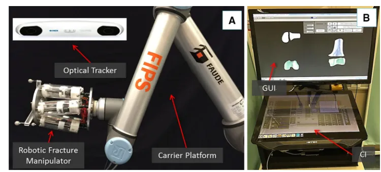
The RAFS system used and improved upon in this research consists of the following components: a robotic fracture manipulator, a carrier platform, the system workstation, and the navigation system. The surgical system set-up is shown in Fig.1n and its main subsystems are briefly described below. For an accurate description of the robotic system configu-ration (i.e. robot structure, workspace, kinematics, control strategy, and architecture), please refer to [23].
Robotic fracture manipulator(RFM) This device (Fig.1a), introduced in [24], is designed to be connected to the bone fragment through an orthopaedic pin for fragment manipula-tion. This component, based on parallel robot configuration with 6-DOF, has 6 motorized linear actuators fully computer-controlled and is able to realize accurate positioning within its workspace (±10.25 mm alongx,y,±15 mm along z and rota-tional limits of±17◦around each axis). It provides a 0.03± 0.01 mm translational accuracy and a 0.12◦±0.01◦rotational accuracy [23]. The device mounts a 6-DOF force/torque load cell enabling a real-time force control. In order to fully cover the required operational workspace (Table 1; Fig. 2), the robotic manipulator is mounted on a carrier platform.
Carrier platform(CP) This device (Fig.1a) is used to posi-tion the RFM (which is connected as its end-effector) close to the orthopaedic pin. The CP provides an extended work space that can cover the required surgical workspace [23]. The RFM is then used to accurately manipulate the frag-ment to the desired, i.e. reduced, pose. The CP has 6-DOF, 3
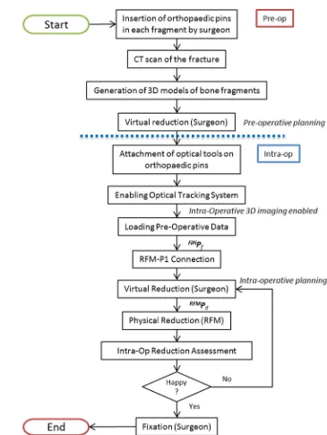
[image:3.595.106.481.516.686.2]Fig. 2 New clinical workflow for RAFS
translations and 3 rotations, covering the required operational workspace summarized above and described in [23].
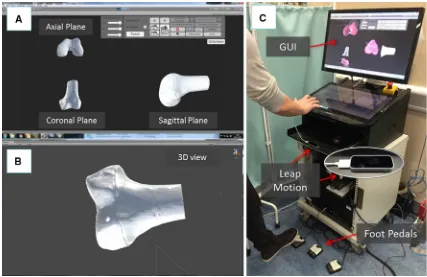
System workstation It employs a host–target structure composed by a PC (host) and a real-time controller with FPGA (target), and a low-level motor controller. The host PC runs the graphical user interface (GUI) and the configu-ration interface (CI) (Fig.1b). It creates the link between the surgical team and the robotic system. The GUI allows the sur-geon to interact with the new navigation system, while the CI is used for system configuration and safety alarm messages. We adopted two separate screens: the GUI is displayed on a large 3D monitor dedicated to the surgeon, while the CI is displayed on a touch screen interface to allow a surgical
assis-tant to change the settings configuration without requiring the surgeon’s intervention. The host PC communicates with the target controller via ethernet. The target controller (NI-compactRIO 9068, National Instruments) processes users’ commands and sends the motion commands to the low-level motor controller (EPOS 2 24/3, Maxon Motor) that executes the movement of the robotic system.
[image:4.595.178.543.47.532.2]for pre- and intra-operative planning of fracture reduction, i.e. virtual reduction. The optical tracking system (Polaris Spec-tra, NDI Inc.) provides a real-time (25 Hz) pose update of the optical tools (0.25 mm accuracy) connected to the bone fragments and the RFM. The optical tools have different and unique geometries to enable real-time tracking. The naviga-tion system is described in the next secnaviga-tion.
Navigation system and system operation
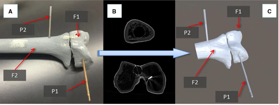
This section describes the new navigation system for robot-assisted reduction in intra-articular fractures of the lower limb, along with a new clinical workflow (Fig. 2). This includes procedures for pre-operative virtual planning, intra-operative navigation, and physical reduction (using the robotic system) of the fracture. Complete two-part distal femur fractures (such as the one shown in Fig.3) have been used for the development and the experimental validation of the proposed navigation system.
Pre-operative planning
The procedure starts with the insertion of the orthopaedic pins into the bone fragments. Pin 1 (P1) is inserted in fragment 1 (F1), and pin 2 (P2) is inserted in fragment (F2), as shown in Fig.3a. These pins will allow fragment manipulation through a small incision, i.e. minimizing the soft tissues damage. A pre-operative CT scan of the fracture and inserted pins is taken, and the resulting data set segmented to generate 3D models (STL format) of each bone fragment and the inserted pins using the ImageSim commercial software (Fig.3b) [26]. These models are imported in the reduction software, and reference frames are defined as shown in Fig.4: (1) The coor-dinate frame CFP1is associated with P1, and the coordinate
frame CFP2is associated with P2. CFP1and CFP2are placed on the centre of the top end of the relative pin and oriented as shown in Fig.5; (2) The coordinate frames CFF1and CFF2are associated with F1 and F2, respectively. CFF1, CFF2,CFP1, and CFP2are measured in the CT image space and processed to get the homogeneous transformations P1TF1 and P2TF2 between P1–F1 and P2–F2, respectively [27]. P1TF1 and P2T
F2 are considered to be constant during the operation. The surgeon virtually reduces the fracture using the reduc-tion software GUI (described below) by manipulating F1 to match F2 (which is kept in a fixed pose) and generating the final poses for F1-P, i.e.F1P1Pf, in the reduced configura-tion. Results of the pre-operative procedure are stored in the system and used for intra-operative navigation, robot motion command calculation, and for the evaluation of the reduction results, as described in the next subsection.
Intra-operative procedure
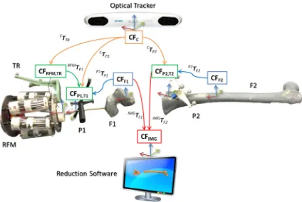
In the operating theatre, fragment F1 needs to be physically aligned to F2. This is accomplished using the robotic sys-tem described in the previous section. The robotic syssys-tem is controlled by software according to the results of the pre-and intra-operative image analysis. The main components of the intra-operative procedure are the reduction software, the optical tracker, the robotic system, and the patient (i.e. the fracture). One optical tool (T1) is placed on the orthopaedic pin (P1) inserted in fragment 1 (F1), and a second optical tool (T2) is placed on the orthopaedic pin (P2) inserted in the reference bone (F2). A further optical tool (TR) is placed on the RFM (see Fig. 8a). The poses of the optical tools are measured in the optical tracking system (CFC), and the corresponding homogeneous transformations CTTR,CTP1, andCTP2can be calculated. The orthopaedic pins P1 and P2 were designed to be connected in a unique way to the
[image:5.595.54.542.511.696.2]Fig. 4 Components and transformations used in our navigation system
Fig. 5 Optical tools T1 and T2 can be connected to their relative pins P1 and P2 in a unique way through a unique connection geometry (a); model of T1 inserted in P1: the coordinate frame of P1(CFP1)is coincident with the coordinate frame of T1(CFT1)(b). Similarly, CFP2≡CFT2
cal tools T1 and T2 (Fig.5), having their coordinate frames coincident, i.e. CFP1 ≡ CFT1, and CFP2 ≡ CFP1. There-fore, assuming thatP1TF1andP2TF2are constant during the operation, the optical tracker provides the actual poses of F1 (by tracking P1) and F2 (by tracking P2). This establishes a direct correspondence between the image space (reduction software, virtual models) and the task space (real fracture) by using the optical tracker, which enables the intra-operative imaging. This is described by the transformationsIMGTF1 andIMGTF2.
[image:6.595.85.509.53.337.2] [image:6.595.115.482.370.531.2]to the RFM (by tracking TR)—calculates the transformation RFMT
P1between the robot and the orthopaedic pin P1. Results of the pre-operative planning, i.e. the virtual reduction parameters, are uploaded into the intra-operative procedure, and the corresponding desired pose for the RFM to achieve the fracture reduction is computed as:
RFM
Pd=RFMTP1×IMGTF1×F1P1Pf (1)
Finally, the RFM executes the desired movement for F1 to achieve the physical reduction in the fracture, while reference bone F2 remains fixed. The real-time imaging updates the actual pose of the fragments in real time, and the surgeon can check intra-operatively the reduction in 3D without the use of any other intra-operative imaging device. If the reduction is acceptable, then the surgeon proceeds with the fixation of the fracture by using plate and screws or intramedullary nail, and the surgery ends.
Graphical user interface (GUI)
The reduction software runs a dedicated GUI (Fig.6) devel-oped using C# programming language on a Windows 7 PC, to allow the surgeon to interact with the navigation sys-tem. The GUI uses the freeware version of the Unity 5.1 engine [28] for the rendering, physics engine, and collision detection of the 3D models to simulate real-world condition
in the virtual environment. A library for accessing the opti-cal tracking system, robot, and controller was established. The GUI combines two separate modalities for pre-operative planning and intra-operative procedure. The pre-operative planning modality allows the surgeon to: (1) load and visu-alize the pre-generated models of the bones; (2) virtually interact with them; and (3) save the pre-operative planning results. The intra-operative procedure modality allows the surgeon to: (1) load and visualize the pre-generated models of the bones; (2) load the pre-operative planning results; (3) provide the actual position of the bones intra-operatively; (4) interact with the bones models, if still required; and (5) gen-erate and send the motion command for the robotic system based on pre- and intra-operative imaging.
The GUI provides the surgeon with 2D views of each anatomical plane (i.e. sagittal, frontal, transverse [29]) and a 3D view of the fracture model (Fig.6a). The 2D views (pro-jections) of the fracture model allow the surgeon to perform a virtual reduction. The 3D view allows the surgeon to move the camera around the model in the virtual environment to assess the outcome of the reduction (Fig6b).
The surgeon interacts with the 3D models through a con-tactless user controller to ensure the sterility of the whole procedure. The user controller chosen for this application is the Leap Motion [30], which is able to track and synthetize a 3D position and orientation of the hands in its workspace. Also, three foot pedals that provide on–off inputs to the
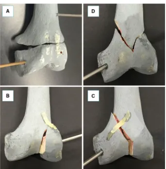
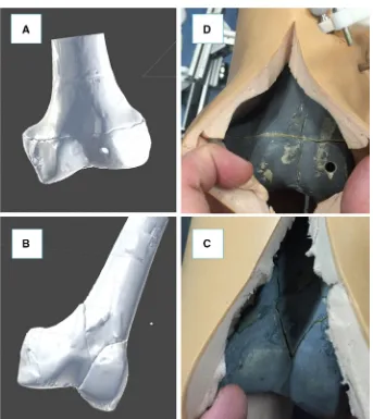
[image:7.595.83.510.408.685.2]Fig. 7 Distal femur fracture types used for the experimental evaluation of the system: simple fracture (a), lateral sagittal (b), medial sagittal (c), and articular Y-shape (d)
tem are included (1) to grab and release the fragment models, (2) to select a specific anatomical plane for interaction, and (3) to merge two fragments together that are further manip-ulated as one fragment (Fig.6c).
Experimental evaluation
The navigation system was tested performing 80 virtual reductions of 4 different 2-fragment distal femur fracture types (20 reductions for each fracture type), following the workflow described in the previous section. The distal femur fracture types chosen for the experimental evaluation (Fig.7) were [5]: (1) simple fracture (33-A1), (2) lateral sagittal (33-B1), (3) medial sagittal (33-B2), and (4) articular Y-shape (33-C1). Also, 80 correspondent physical reductions were performed using the robotic system. A leg model has been manufactured ad hoc by Sawbones (Vashon Island, WA, USA). The leg includes solid-foam femur, patella, tibia, and fibula, encased in semi-flexible foam simulating the skin and the soft tissue surrounding the joint (i.e. muscles and flesh). Also, rubber bands were connected between the distal part of the femur and the proximal part of the tibia, in order to
sim-ulate knee ligaments (i.e. ACL, PCL, LCL, and MCL [31]). The experimental set-up is shown in Fig.8.
Pre-operative procedure
Two orthopaedic pins—P1 and P2—were inserted into the unbroken femur models: P1 in the distal part of the femur and P2 in the femur shaft (Fig.5a). The relative pose of P1 with respect to P2 was obtained by temporarily placing two opti-cal tools on the pins (T1 and T2 on P1 and P2, respectively) through the optical tracker. This relative pose,F1P1Pgoal, rep-resents the ground truth for the reduction assessment, i.e. the target pose to reduce the fracture. The two optical tools T1 and T2 were removed from the pins.
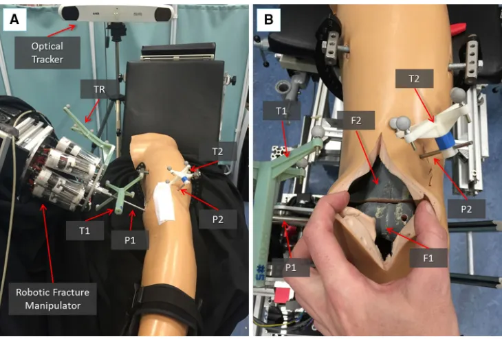
[image:8.595.203.545.49.396.2]soft-Fig. 8 Experimental set-up: the robotic system is connected to the frac-ture fragment F1 through the orthopaedic pin P while P2 is inserted into the femur fragment F2 acting as a reference. The infrared camera tracks
both the robot and the fragments through the optical tools TR, T1, and T2 (a); close-up of the fracture fragments and the inserted pins with optical tools (b)
ware for the pre-operative surgical planning (see Figs.3,6). An orthopaedic surgeon was asked to virtually reduce each fracture 20 times, by manipulating F1 to match F2. Once the reduction is completed, the final (i.e. desired) poseF1P1Pf of F1-P1 in the image space was stored.
Intra-operative procedure
In the operating theatre, the fractured bone models with inserted pins were placed inside the leg model (Fig. 8). Optical tools F1 and F2 were placed again on P1 and P2, respectively, and the optical tracker turned-on, enabling the intra-operative imaging and showing the actual pose of the two bone fragments in the GUI. The CP positioned the RFM close to P1, which was then connected to the RFM, as described in the previous section. Results from the pre-operative planning (F1P1Pf)were imported into the intra-operative procedure, and the reduction software calculated the desired poseRFMPdfor the RFM in the task space using equation (1). Finally, the robot executed the physical reduc-tion, and the actual pose of F1-P1 (F1P1Pa) after the reduction was measured by the optical tracker.
Evaluation metrics and results
During the experiments described above, the final poses of F1-P1 after the pre-operative virtual reduction (F1P1Pf)and
after the intra-operative physical reduction using the robot (F1P1Pa)of each fracture were saved for subsequent com-parison with the desired pose for F1-P1 in its unbroken configuration (F1P1Pgoal). These comparisons allowed the objective evaluation of the surgical system accuracy, mea-sured as: (1) virtual reduction accuracy, and (2) physical reduction accuracy. The metrics chosen for the system accu-racy evaluation were the root-mean-squared error (RMSE), and the maximum absolute error (MAE) measured during both virtual and physical reductions. Also, the time employed to complete each reduction (both virtual and physical) was recorded as a system performance evaluation metric. Finally, the average load applied during the physical reduction was calculated to analyse the contact forces and torques between the RFM and the leg (i.e. bones and soft tissues).
Results from evaluation experiments are reported in Table2(virtual reduction) and Table3(physical reduction), while visual reduction examples are shown in Fig.9.
Discussion
[image:9.595.115.480.53.300.2]Table 2 Results—virtual
reduction Fracture type Number of reductions RMSE MAE Reduction time (s)
Metaphyseal fracture 20 0.95±0.3 mm 1.03 mm 73.4±12.7
(33-A1) 1.02◦±0.1◦ 1.15◦
Lateral sagittal 20 0.83±0.13 mm 0.96 mm 79.8±22.8
(33-B1) 0.89◦±0.3◦ 1.38◦
Medial sagittal 20 0.86±0.25 mm 1.3 mm 93.9±51.3
(33-B2) 1.02◦±0.33◦ 1.5◦
Complete articular 20 0.94±0.1 mm 1.5 mm 134.2±55.9
[image:10.595.57.540.219.347.2](33-C1) 1.4◦±0.5◦ 3.15◦
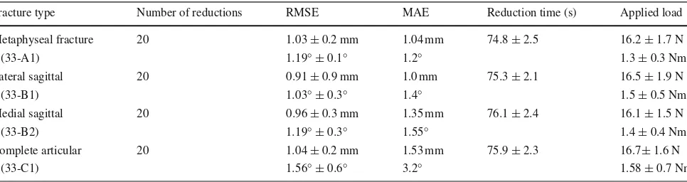
Table 3 Results—physical reduction
Fracture type Number of reductions RMSE MAE Reduction time (s) Applied load
Metaphyseal fracture 20 1.03±0.2 mm 1.04 mm 74.8±2.5 16.2±1.7 N
(33-A1) 1.19◦±0.1◦ 1.2◦ 1.3±0.3 Nm
Lateral sagittal 20 0.91±0.9 mm 1.0 mm 75.3±2.1 16.5±1.9 N
(33-B1) 1.03◦±0.3◦ 1.4◦ 1.5±0.5 Nm
Medial sagittal 20 0.96±0.3 mm 1.35 mm 76.1±2.4 16.1±1.5 N
(33-B2) 1.19◦±0.3◦ 1.55◦ 1.4±0.4 Nm
Complete articular 20 1.04±0.2 mm 1.53 mm 75.9±2.3 16.7±1.6 N
(33-C1) 1.56◦±0.6◦ 3.2◦ 1.58±0.7 Nm
that the proposed navigation system created for the RAFS system is able to meet the reduction accuracy requirements for joint fracture surgeries, i.e. 1 mm and 5◦(Table1). The metrics chosen for the system accuracy evaluation, i.e. RMSE and MAE, are strictly related to the operational safety and efficiency of the surgical system. In general, high values of RMSE and MAE give an account of how far the manipu-lated fragment is from the desired, i.e. reduced, position, and physical reduction procedures.
The navigation system allowed the surgeon to virtually reduce all the fractures with a maximum residual positioning error (RMSE) lower than 1 mm, 5◦(clinical requirements, Table1). The best result was obtained reducing lateral sagittal fractures (33-B1) with a residual positioning error (RMSE) of 0.83±0.13 mm and 0.89◦±0.3◦. A similar result was obtained reducing medial sagittal fractures (33-B2), as shown in Table 2. Metaphyseal fractures (33-A1) and complete articular fractures (33-C1) resulted more challenging with a residual positioning error (RMSE) of 0.95±0.3 mm and 1.02◦±0.1◦, and 0.94±0.1 mm and 1.4◦±0.5◦, respec-tively. The correspondent physical reduction accuracies are reported in Table3. This data demonstrate that the RAFS system is able to meet the clinical requirements of 1 mm, 5◦ presenting a maximum residual positioning error (RMSE) of 1.04±0.2 mm and 1.56◦±0.6◦(complete articular frac-tures), when the robot reduced the fractures. This result is achieved thanks to the sub-millimetre positioning
accu-racy of the robotic system, which is 0.09 mm and 0.15◦as demonstrated in [23]. Moreover, the measured MAEs fur-ther demonstrated that the system permits excellent reduction accuracies (both virtual and physical), helping the surgeon to avoid large deviations from the desired reduction. Results demonstrated that the residual inaccuracies are mainly due to the virtual reduction procedure rather than the physical one. This can be further improved by creating 3D virtual models of the bones from CT data with a better resolution, i.e. using a high-resolution CT scanner. However, the experiments also demonstrated that the proposed system has a higher reduc-tion accuracy when compared with other systems based on 3D imaging reported in the literature such as [9–11,13–
Fig. 9 Experimental validation results examples: virtual reduction in the fracture performed by the surgeon on a simple fracture (a) and on an articular Y-shape fracture (b); correspondent physical reduction achieved by the robotic system, (c,d) respectively
image is required) and results in a sub-millimetre registra-tion accuracy between 2D and 3D images. However, only the accuracy of image registration and calibration has been assessed, while the physical fracture reduction accuracy eval-uation is not shown. The automated traction table proposed by Warisawa et al. [11] presented an average positioning error of only 0.57 mm and 0.12◦, but it seems applicable only to shaft fractures given its non-invasive attachment to the patient’s foot. The system proposed by Westphal et al. [13,14] presented a reduction displacement of about 2 mm and 2.9◦ on femur shaft reductions, which is not sufficient for intra-articular fractures. Wang et al. [21] designed a parallel robot mechanism to reduce femur shaft fractures with an accu-racy of 2.43±0.49 mm (lateral translation) and 2.26◦±0.23◦ (angulation), which is, again, not acceptable for joint frac-tures. A similar system from Tang et al. [15] resulted in a residual deviation of 1.24±0.65 mm for the axial deflec-tion, 1.19±0.37 mm for the translation, 2.34◦±1.79◦for the angulation, and 2.83◦±0.9◦for the rotation (on bovine femur shaft fractures). However, this system requires a CT
scan of both limbs (both injured and healthy side) and the connected robot, and lacks intra-operative real-time image guidance.
The average time the surgeon took to virtually reduce 80 fractures using the navigation system is about 95 sec-onds. Similarly, the robot employed on average about 75 seconds to physically reduce the fracture based on the virtual reduction. Therefore, the entire reduction procedure can be accomplished in about 3 minutes, arguably speeding up the entire fracture surgery.
[image:11.595.203.546.49.434.2]in average force of about 16.3 N and average torque of 1.4 Nm (Table3). The average loads measured during the tri-als are comparable (slightly lower, due to the absence of real soft tissues in our model) than the loads measured dur-ing experiments conducted on ex vivo animal specimen [23], and during real fracture surgeries [12,32]. The load measured during the reduction in different fracture types is roughly the same, which shows that it does not depend on the shape of the fracture but on the contact between the manipulation pins and the leg model. This is also an indicator of correct reduction trajectories for different fracture types, i.e. the manipulated fragments smoothly reach the desired positions.
Conclusion
In this paper, we presented a navigation system which allows the surgeon to virtually reduce bone fractures, i.e. distal femur fractures. The motion commands generated by the navigation system are sent to our robotic system which phys-ically reduces the fracture.
The bone fragments are segmented from a pre-operative CT scan, and 3D virtual models are generated. Fragments are visualized on the screen and can be virtually manipu-lated through the dedicated contactless GUI. The fracture is reduced by moving the fragments to the desired target position, thereby completing the pre-operative planning pro-cedure. During the surgery, the actual position of the bone fragments is provided by an optical tracker enabling real-time 3D imaging. The surgeon monitors the reduction process and can correct and modify the virtual reduction intra-operatively if required. The motion commands for the robot connected to the bone fragment are generated, and the fracture physically reduced based on the surgeon’s virtual reduction using the navigation system.
Experimental outcome demonstrates the accuracy and effectiveness of the proposed navigation system, presenting a fracture reduction accuracy of about 1 mm and 1.5◦—when used in conjunction with our robotic system—meeting the clinical requirements for distal femur fracture reduction pro-cedures.
In summary, the major advantages of the proposed sys-tem are as follows: (1) enhanced 3D visualization required to better understand the three-dimensional fracture configura-tion; (2) the reduction strategy can be accurately pre-planned by the surgeon; (3) immediate evaluation of the reduction results through the real-time 3D guidance; and (4) accu-rate and safe robotic assistance for the physical reduction in the fracture with minimized soft tissue damage (minimally invasive approach) for a better clinical outcome. The actual hardware configuration allows the physical reduction in only one fragment at the time. In the next step of development, a second robot (CP + RFM) will be included in the system
to allow simultaneous manipulation of two fragments. This will allow treatment for other types of distal femur fractures (e.g. multi-fragmented), but also fractures of other joints, e.g. pelvis, ankle, neck of femur, and upper-limb joints.
Further studies are planned in the optimization of the navigation system through the implementation and eval-uation of different user controllers which can potentially further improve the virtual reduction accuracy of the system. Usability study with experienced surgeons is also planned to evaluate the performance of the navigation system, gathering not only objective measurements from the surgeons’ perfor-mance using the system but also their subjective perception of it. Moreover, cadaveric trials will be shortly conducted.
Acknowledgments This is a summary of independent research funded by the National Institute for Health Research (NIHR)’s Invention for Innovation (i4i) Programme. The views expressed are those of the author(s) and not necessarily those of the NHS, the NIHR, or the Depart-ment of Health.
Funding
This study was funded by the National Institute for Health Research, United Kingdom (II-SB-0712-20002).
Compliance with ethical standards
Conflict of interest Giulio Dagnino, Ioannis Georgilas, Paul Köhler, Samir Morad, Roger Atkins, and Sanja Dogramadzi declare that they have no conflict of interest.
Ethical approval This article does not contain any studies with human participants or animals performed by any of the authors.
Informed consent Statement of informed consent was not applicable since the manuscript does not contain any participants data.
Open Access This article is distributed under the terms of the Creative Commons Attribution 4.0 International License (http://creativecomm ons.org/licenses/by/4.0/), which permits unrestricted use, distribution, and reproduction in any medium, provided you give appropriate credit to the original author(s) and the source, provide a link to the Creative Commons license, and indicate if changes were made.
References
1. Rüedi T, Buckley R, Morgan C (2007) AO principles of fracture management, books and DVD, 2nd edn. Thieme, AO Pub, Stuttgart, New York
2. Kulkarni GS (2008) Textbook of orthopaedics and trauma. Jaypee Brothers, New Delhi
3. Dobbe JGG, Strackee SD, Schreurs AW, Jonges R, Carelsen B, Vroemen JC, Grimbergen CA, Streekstra GJ (2011) Computer-assisted planning and navigation for corrective distal radius osteotomy, based on pre- and intraoperative imaging. IEEE Trans Biomed Eng 58:182–190. doi:10.1109/TBME.2010.2084576
4. Merchan EC, Maestu PR, Blanco RP (1992) Blade-plating of closed displaced supracondylar fractures of the distal femur with the AO system. J Trauma 32:174–178
6. Rammelt S, Amlang M, Barthel S, Gavlik J-M, Zwipp H (2010) Percutaneous treatment of less severe intraarticular calcaneal frac-tures. Clin Orthop 468:983–990. doi:10.1007/s11999-009-0964-x
7. Hutson JJ, Zych GA (2000) Treatment of comminuted intraarticular distal femur fractures with limited internal and external tensioned wire fixation. J Orthop Trauma 14:405–413
8. Gaston P, Will EM, Keating JF (2005) Recovery of knee func-tion following fracture of the tibial plateau. J Bone Joint Surg Br 87:1233–6
9. Buschbaum J, Fremd R, Pohlemann T, Kristen A (2014) Computer-assisted fracture reduction: a new approach for repositioning femoral fractures and planning reduction paths. Int J Comput Assist Radiol Surg 10:149–159. doi:10.1007/s11548-014-1011-2
10. Joskowicz L, Milgrom C, Simkin A, Tockus L, Yaniv Z (1998) FRACAS: a system for computer-aided image-guided long bone fracture surgery. Comput Aided Surg Off J Int Soc Com-put Aided Surg 3:271–288 doi:10.1002/(SICI)1097-0150(1998)3: 6<271::AID-IGS1>3.0.CO;2-Y
11. Warisawa S, Ishizuka T, Mitsuishi M, Sugano N (2004) Develop-ment of a femur fracture reduction robot. IEEE Int Conf Robot Autom. doi:10.1109/ROBOT.2004.1308896
12. Georgilas I, Dagnino G, Tarassoli P, Atkins R, Dogramadzi S (2015) Preliminary analysis of force-torque measurements for robot-assisted fracture surgery. EMBC 2015 Conf. doi:10.1109/ EMBC.2015.7319491
13. Westphal R, Gösling T, Oszwald M, Bredow J, Klepzig D, Winkel-bach S, Hüfner T, Krettek C, Wahl F (2008) Robot assisted fracture reduction. In: Khatib O, Kumar V, Rus D (eds) Exp. Robot. Springer, Berlin, pp 153–163
14. Westphal R, Winkelbach S, Wahl F, Gösling T, Oszwald M, Hüfner T, Krettek C (2009) Robot-assisted long bone fracture reduction. Int J Robot Res 28:1259–1278. doi:10.1177/0278364909101189
15. Tang P, Hu L, Du H, Gong M, Zhang L (2012) Novel 3D hexapod computer-assisted orthopaedic surgery system for closed diaphy-seal fracture reduction. Int J Med Robot 8:17–24. doi:10.1002/rcs. 417
16. Graham AE, Xie SQ, Aw KC, Xu WL, Mukherjee S (2006) Design of a parallel long bone fracture reduction robot with planning treatment tool. In: 2006 IEEERSJ Int Conf Intell Robots Syst, pp 1255–1260
17. Zheng G, Dong X, Zhang X, Nolte L-P (2005) Automated detection and segmentation of diaphyseal bone fragments from registered C-arm images for long bone fracture reduction. In: Eng Med Biol Soc 2005 IEEE-EMBS 2005 27th Annu Int Conf Of, pp 4361–4364
18. Hofstetter R, Slomczykowski M, Krettek C, Köppen G, Sati M, Nolte L-P, Müller ME (2000) Computer-assisted fluoroscopy-based reduction of femoral fractures and antetorsion correction. Comput Aided Surg 5:311–325. doi:10.3109/10929080009149849
19. Nakajima Y, Tashiro T, Sugano N, Yonenobu K, Koyama T, Maeda Y, Tamura Y, Saito M, Tamura S, Mitsuishi M, Sugita N, Sakuma I, Ochi T, Matsumoto Y (2007) Fluoroscopic bone fragment tracking for surgical navigation in femur fracture reduction by incorporating optical tracking of hip joint rotation center. IEEE Trans Biomed Eng 54:1703–1706. doi:10.1109/TBME.2007.900822
20. Marsh JL (2015) Rockwood and green’s fractures in adults, 8th edn. Wolters Kluwer, Alphen aan den Rijn
21. Wang J, Han W, Lin H (2013) Femoral fracture reduction with a parallel manipulator robot on a traction table. Int J Med Robot Comput Assist Surg. doi:10.1002/rcs.1550
22. Raabe D, Dogramadzi S, Atkins R (2012) Semi-automatic per-cutaneous reduction of intra-articular joint fractures—an initial analysis. In: IEEE Int Conf Robot, Autom
23. Dagnino G, Georgilas I, Tarassoli P, Atkins R, Dogramadzi S (2015) Vision-based real-time position control of a semi-automated system for robot-assisted joint fracture surgery. Int J Comput Assist Radiol Surg 1–19: doi:10.1007/s11548-015-1296-9
24. Dagnino G, Georgilas I, Tarassoli P, Atkins R, Dogramadzi S (2015) Design and real-time control of a robotic system for fracture manipulation. EMBC 2015 Conf
25. Dagnino G, Georgilas I, Tarassoli P, Atkins, R, Dogramadzi S (2015) Intra-operative 3D imaging system for robot-assisted frac-ture manipulation. EMBC 2015 Conf
26. ImageSim. Volmo Ltd
27. Siciliano B, Khatib O, DESIGN D handbook of robotics by Bruno Siciliano and Oussama Khatib: handbook of robotics. digital designs
28. Unity. Unity Technologies
29. Anatomical plane (online). https://en.wikipedia.org/wiki/ Anatomical_plane. Accessed 11 Jan 2016
30. Leap Motion. Leap Motion, San Francisco, CA, USA
31. Bellemans J, Ries MD, Victor JMK (2005) Total knee arthroplasty. Springer, Berlin