-
---
--
®
-
---
---
- -
-
-
- --
--
-
-
-
-
--
-
-
~--
--
--
-
-USER1S GUIDE
for the
ULCnet Connector Adapter
and the
DOCUMENTATION COPYRIGHT
Copyright (c) 1983 by Orange Compuco, Inc. All rights reserved. No part of this User's Guide may be reproduced, transmitted, transcribed, stored in a retrieval system, or translated into any language or computer language, in any form or by any means elec-tronic, mechanical, magnetic, optical, chemical, manual or other-wise, without the prior written permission of Orange Compuco, Inc.
SOFTWARE COPYRIGHT
Copyright (c) 1983 by Aquinas, Inc. All rights reserved. No part of these programs may be reproduced, transmitted, transcribed, stored in a retrieval system, or translated into any language or computer language, in any form or by any means electronic, me-chanical, magnetic, optical, chemical, manual or otherwise
(except a maximum of five backup copies may be reproduced), without the prior written permission of Aquinas, Inc.
DISCLAIMER
Orange Compuco, Inc. and Aquinas, Inc. make no representation or warranties with respect to the contents hereof and specifically disclaim any implied warranties of merchantability or fitness for any particular purpos e. Further, Aquinas and Orange reserve the right to revise these programs and to make changes from time to time in the content hereof without obligation of Aquinas or Orange to notify any person or organization of such revision or changes.
TRADEMARK
TABLE OF CONTENTS
Chapter Title/Subject
1 INTRODUCTION TO ULCnet and the ULC-OPSnet OPERATING SYSTEM
General . . . . Component s . . . • . . . • . . . Features . . . . Command s . . . • • . . . ...• Memory Requirements . . . . Software . . . • . . . • . . . • Gatekeeper Software . . . . Workstation Software . . . . • • . . . . • . . . • . . • Self Clocking Operation ...•.... Software Updates and Assistance . . . • . . • What This Package Contains . . . . Other Necessary Equipment • . . . • . . . •
2 THE ULCnet CONNECTOR ADAPTER
Installation . . . • . . . • . • • . . . • . . . . • . . . Installing the Signal Carrier Board . . . . Operation . . . • . . . • • • • • • . . . •
3 GETTING STARTED
Care of Diskettes . . . . Installing the ULC-OPSnet Gatekeeper on
a KAYPRO Model 2 or 4 ...•.... Installing the ULC-OPSnet Gatekeeper on
a KAYPRO Model 10 . . . • Installing the ULC-OPSnet Workstation
on a KAYPRO Model 2 or 4 . . . . Installing the ULC-OPSnet Workstation
on a KAYPRO Model 10 . . . . Testing the Network . . . • . • . • . . . • . Review . . . . • . . . • . . .
4 NETWORK ENVIRONMENT, SYSTEM ACCESS, AND FILE SECURITY
Introduction . • • . . . • . . . • . . . . System Access Security • . . . • • • . • The REACT. COM Program - Changing
Passwords and Privilege Levels . . . . • • . . . File Security • • . . . • . . . • . . . . Other Recommended Security Measures .••.•• Pre-Determined, Automatic Initialization. Automatic Load of ULC-OPSnet • . • . . .
Chapter
TABLE OF CONTENTS (Continued)
Title/Subject
How to Auto-Load ULC-OPSnet on
a KAYPRO Model 10 • . . . • • . . . • . . • • . . • Procedure for KAYPRO Model 10 Hard Disk •. Procedure for KAYPRO Model 10 Bootable
Floppy Diskettes . . . . How to Auto-Load ULC-OPSnet on the
KAYPRO Models 2 and 4 ••••••••••••••••••
5 ASSIGNMENT OF DEVICES
The "WHERE" Command (Obtaining a Table of Device Assignments) . . . . The "ASSIGN" Command (Changing the Table
of Logical Drive Assignments) . . . • The "SPOOL" Command (Assigning a Printer
to a Workstation) . . . • . . . Getting Information about Files
on the Network . . . • . . . • . . . • . The "LOCATE" Command . . . • . . . Getting RAM Information and Performing a
Re s et . . . • . . • .
6 OTHER ULC-OPSnet OPERATIONS
Printing a File . . . • . . . • . . • . Printing Files With Special Word
Processing Printer Drivers . . . . Interstation Messages . . . • . . . • . . . . • Electronic Mail . . . • . . . • . . . File Transfers Over the Network . . . . Changing User ID . . . • . . . • • . • . . . • . . Assistance From ULC-OPSnet . • • . . . • . • . Bringing Up the Network . • . . . • . . • . . . • • . Leaving the System •...•.••.••..••••...•
7 OPERATIONAL AND APPLICATIONS CONSIDERATIONS WITH ULCnet
Introduction . . . . • . . . • • . • . . • • • . . . . • . • . Operating Procedures ..•.••.••.••..•....•• Applications Considerations . . . • . • . . . •
8 TECHNICAL CONSIDERATIONS FOR PROGRAMMING AND OPERATIONS
Placement of .COM and .OV? Files •.•.•.... - Search path for loading programs . . . • . - Overlay autosearch . . • . • • • . . . • .
Chapter
TABLE OF CONTENTS (Continued)
Title/Subject
- PIPing Overlay files . . . . - Using autosearch in operational
proce-dures7 i.e., where to put programs .•. - Performance impact of program location. Multi-User File Operations Under
ULC-OPSnet . . . . - How to implement File Lock in an appli-cation program . . . . - Sample dBASE-II command file with File
Lock implemented . . . . - Operational considerations 7 using the
.DBU file extension . . . • . . . - PIPing files with the .DBU extension ... Restricted ASCII Characters and File
Names in ULC-OPSnet . . . . - Table of ASCII Characters and HEX equi-valents . . . . - Restricted .COM filenames . . . • . . . Submit operations with OSUB.COM, OXSUB.
COM, and PSUB.COM • . . . - Enhancements to CP/M equivalents . . . . - Syntax and operational compatibility .. . Other Procedural and Operational
Consider-ations with ULCnet . . . • • . . . - The RETRY command and its effect . . . . - Limitations of the SEND command . . . . • • . . - Reserved Virtual Disk designations . . . Additional XBDOS Calls Implemented in
ULC-OPSnet . . . . XBDOS Call Examples • . . .
9 SUMMARY OF COMMANDS AND ERROR MESSAGES
Command Summary . . . . • . . . • . . Classification of Commands . . . . Error Messages • . . . . • . . .
LIST OF ILLUSTRATIONS
Figure
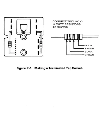
2-1 Making a Terminated Tap Socket.
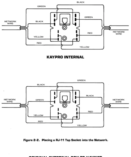
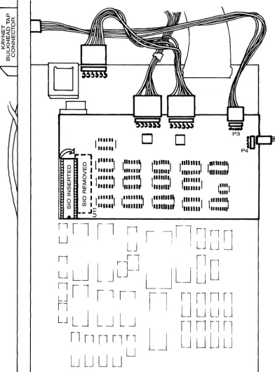
2-2 Placing a RJ-ll Tap Socket into the Network. 2-3 Installing the Network Circuit Board.
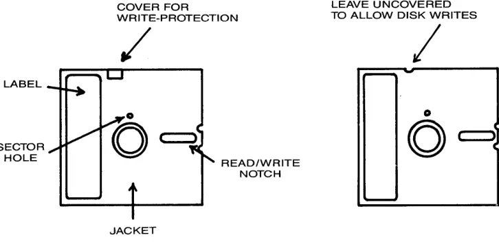
3-1 Write Protection for an 5-1/4" Diskette.
8-2 8-2 8-3 8-3 8-3 8-4 8-4 8-4 8-4 8-6 8-7 8-7 8-7 8-7 8-8 8-8 8-8 8-8 8-9 8-12 9-1 9-1 9-5
GENERAL
CHAPTER 1
INTRODUCTION TO ULCnet and the
ULC-OPSnet OPERATING SYSTEM
You have purchased a complete networking system for the KAYPRO Models 2, 4, 10, and Robie line of microcomputers. Most other Z80 based CP/M(c) microcomputers may be added to the net-work as long as they are equipped with a RS-232C serial port driven by a Zilog SIO PUSART (or equivalent) and capable of transmitting and receiving synchronously. The software and hard-ware to connect many other brands of microcomputers to your ULCnet(c) may be special ordered from your KAYPRO dealer.
COMPONENTS
The networking components are divided into three groups: (1) the KAYNET/ULCnet Connector Adapter PCB's (hardware), (2) the network media, i.e., the four conductor telco cable, RJ-ll terminators and RJ-ll tap sockets, and (3) the ULC-OPSnet(c) network operating system (software) contained on diskettes. Chapter 2 is devoted to the installation and operation of the KAYNET/ULCnet Connector Adapter PCB's and network media while the remainder of the chapters are devoted to installing and using the network operating system.
NOTE: All Figures (illustrations and tables) are contained in Appendix i and are appropriately referenced in the text of this manual.
Once the network wire and tap sockets have been installed, the KAYNET!ULCnet Connector Adapter PCB's have been connected to both the network and to their respective microcomputers, and the microcomputers have been powered up, the ULC-OPSnet software is ready to be installed. Once the software is completely installed (see Chapters 3 and 4) the entire network is ready for use.
FEATURES
ULC-OPSnet provides the ability to assign any remote pe-ripheral devices on the network as local devices for a particular workstation. Therefore, programs may be executed, files may be opened, processed, copied and, listed by any station on the net-work, even though they may reside on any other station on the network. A remote printer may be accessed from any station, and
(c) - Signifies trademark and/or copyright.
ULCnet is a registered trademark of Orange Compuco, Inc. OPSnet is a registered trademark of Aquinas, Inc.
since printing operates in the background mode, the station to which the printer is attached is available for processing while the printer is operating. Disk I/O serving also operates in background mode. Thus an operator may be processing at Station #1 while other stations on the network are being serviced by the disk drives attached to Station #1.
Messages may be sent from one station to another. They are displayed on the destination station's console device, or if that station is busy, electronic mail may be employed such that mes-sages queue up in a station's "mail box."
Complete security is provided by a comprehensive access security system, limiting system use with a combination of passwords, privilege levels, and user identification numbers (USER ID' s). The system further permi ts files to be designated "private" or "sharable" and "locked" or "unlocked." A facility is also provided which will support a dynamic file lock status for multi-user applications.
The command structure for ULC-OPSnet is discussed beginning with Chapter 5. ULC-OPSnet supports three classes of commands:
1. The General Commands 2. The Network Commands
3. The Enhanced CP/M Commands
COMMANDS
This User's Guide is concerned with the use of the General and Network commands which provide for using the operating system and maximizing the use of network concepts. The ULC-OPSnet operating system interprets CP/M commands and all CP/M commands are avail-able as described in your CP/M manual. Enhanced versions of these same CP/M commands which are described in Chapter 9 are available under ULC-OPSnet and may be used without leaving ULC-OPSnet. The technical distinctions between the CP/M commands and their en-hanced counterparts in ULC-OPSnet are discussed in the ULC-OPSnet Technical Manual.
MEMORY REQUIREMENTS
As a general rule, any application program which operates under CP /M and which requires up to 7K bytes of storage less than the TPA for your current CP/M operating system will run under ULC-OPSnet. The standard TPA size for the KAYPRO Models 2 and 4 is 56K. Thus, the useable TPA for the KAYPRO Models 2 and 4 with ULC-OPSnet is 49K. The useable TPA for the KAYPRO Model 10 with ULC-OPSnet is 48K.
SOFTWARE
The ULC-OPSnet software is distributed in two versions:
1. The Gatekeeper software 2. The Workstation software
Each of these versions is distributed on a diskette. Both Gate-keeper and Workstation software are distributed on a double-density 5-1/411 diskette. The content of the User's Guide for
each version is identical. One Gatekeeper version is required per network while the number of Workstation versions required is equal to the number of stations to be placed on the network minus one (the Gatekeeper counts as one workstation). The Gatekeeper software may reside on either a hard disk or a floppy disk system.
GATEKEEPER SOFTWARE
ULC-OPSnet provides that one station on the network is to be designated as the Gatekeeper. In addition to the standard Work-station software, the systems disk for the Gatekeeper Work-station contains additional software routines which perform network management functions. A station on the network may become the Gatekeeper merely by using the Gatekeeper systems disk on that station.
The functions of the Gatekeeper are:
1. Permits the Gatekeeper operator to determine which operators and which functions are active on the network at any time.
2. Checks tha t all station identi f i cation numbers (entered during network operations) are unique.
3. Manages the assignment and/or modification of all user numbers, passwords, and privilege levels for all opera-tors on all stations.
4. Provides an affirmative response to a remote station's inquiry as to the presence of a Gatekeeper.
5. Checks that all serial numbers on the various worksta-tions are unique.
WORKSTATION SOFTWARE
ULC-OPSnetis independently installed on each workstation. User numbers, passwords, and privilege levels unique to the operators of a given station are assigned during that station's installation phase. When attempting to bring up a workstation on the network, ULC-OPSnet requires that the Workstation software first check the network for the presence of a Gatekeeper. Upon an affirmative response, the Workstation software continues the ini tialization function.
SELF CLOCKING OPERATION
The KAYPRO Models 2, 4 and 10 each utilize a Zilog SIO PUSART as the serial port controller chip. The Zilog SIO gen-a clock sync pulse cgen-apgen-able of providing communicgen-ations gen-at synchronous baud rates of up to 307. 2K baud. The KAYNET /ULCnet Connector Adapter PCB for the KAYPRO Models 2, 4 and 10 runs in the synchronous mode. A switch is provided next to the KAYNET RJ-ll jack toeitherthe Networkorthe communications serial port.
SOFTWARE UPDATES AND ASSISTANCE
Prior to opening the package containing this manual, you were asked to read the attached License Agreement which describes the terms under which this software may be used. Included with the License Agreement is the Software Registration Card. At this point, please fill out the card and mail as indicated. Unless the Software Registration Card is on file, you will not receive software updates or be entitled to participation in the software performance program. Note that a Software Registration Card is required for each package of software purchased. If, after following the instructions in this manual, you have any problems with the software, please complete the Software Performance Report and mail as indicated. Problems with hardware items should be brought to the attention of your dealer.
WHAT THIS PACKAGE CONTAINS
You should have purchased one Gatekeeper software package and the number of Workstation software packages equal to the number of workstations you intend to network minus one (the Gatekeeper counts as one workstation). Check that the Gatekeeper version contains a diskette marked "GATEKEEPER VERSION" and that each Workstation version contains a diskette marked "WORKSTATION VERSION. II Report any discrepancies to your dealer.
OTHER NECESSARY EQUIPMENT
You should also have purchased one KAYNET /ULCnet Connector Adapter Kit for each KAYPRO computer to be placed on the network. The carton containing the Connector Adapter Kit should include:
1 - KAYNET/ULCnet Connector Adapter PCB. 1 - 6' Interconnect cable (RJll).
1 - Tap socket (RJll).
CHAPTER 2
THE ULCnet CONNECTOR ADAPTER
INSTALLATION
The ULCnet Connector Adapter is a transceiver device designed to interface the serial RS-232C port of a Z80 based microcomputer which runs the CP/M operating system to a network whose medium is a four-conductor telco cable. Connections to the network wire are made via common RJ-ll plugs and tap sockets which are readily available from your dealer or any electronics supply house.
The tap sockets at either end of the network must be termi-nated in order to provide for a balanced line. These special terminated tap sockets may be purchased from your dealer or made up from ordinary tap sockets as shown in Figure 2-1.
The total length (terminator-to-terminator) of the network wire may be up to 2,500 feet, with 7 or fewer Connector Adapters attached, or up to 1,000 feet with the maximum 64 Connector Adapters attached. Common RJ-ll tap (in-line) sockets are used to tap into the network wire at any convenient location. To install a tap socket, first pry off the cover which exposes 12 connector lugs (6 on each side of the RJ-ll socket) and proceed as follows:
IMPORTANT NOTE: ULCnet utilizes low-cost, unshielded telco wire. This reduces overall cost of implementation and makes ULCnet " user installable.1I
To comply with FCC regulations, ULCnet generates a very low energy signal. The signal recei-vers inside of the ULCnet connector adapter are thus suscep-tib1e to some outside interference, such as fluorescent ba1last transformers and AC induction motors. Please make certain that the network wire is at least 12" away from any fluorescent 11ghts and a1r-cond1t10n1ng fan motors. Other-wise, network performance may be degraded by forced packet retransmissions.
1. Layout the network wire along th~ floor next to the baseboard. The network wire may be strung inside walls, over the ceiling or in any convenient fashion to reach all offices in which there will be network connections.
3. Mount (staple) the network wire along the baseboard to the next desired tap point. Cut the wire. Strip outer sheathing leaving about 1-1/2" of the four colored wires exposed. Similarly, strip about 1-1/211 of the outer
sheathing from the unstapled end of the network wire.
4. Push corresponding colors of wire onto available lugs with the tip of a needle-nose pliers. Do this for the four wires coming into the tap socket and the four wires leaving the tap socket (see Figure 2-2). Note that the standard ULCnet tap has two available lugs for each of the four colors. The terminator tap has only one avail-able lug for each color (the other lug on the terminator tap is used for the termination resistor). Fasten tap to wall with screws provided and snap on the cover.
5. Continue as above until all desired taps are installed. The final tap in the network must be a terminator.
Note: A proper installation of the physical network media is critical to system performance_ Tap sockets should be permanently mounted to avoid dangling wires
sub-ject to breaking- Although not mandatory, a good practice is to solder the wires to the lugs after the locations have been finalized.
Line balance on the completed network may be checked with an accurate VOM. Resistance measurements should be taken between the red and black wires (Net A) and between the yellow and green wires (Net B). The following table shows the range of resistance values for standard 4 conductor telco wire which should appear for various lengths of network. Measurements are taken without any connections between RJll tap sockets and Connector Adapters.
Length of Network
(ft. )
100 200 300 400 500
Resistance (ohms)
49-54 50-55 51-56 52-57 53-58
2-2
Length of Network
(ft. )
600 700 800 900 1,000
Resistance (ohms)
INSTALLING THE KAYNET/ULCnet NETWORK CIRCUIT BOARD
The KAYNET/ULCnet NCB (Network Circuit Board) for KAYPRO models with the universal mother board contains all of the Net-work circuitry, harness connecting pins, and a forty (40) pin IC socket. This NCB must be properly installed in order for ULCnet and the computer's keyboard to operate. The installation proce-dure involves removing the cover of the KAYPRO computer, removing an SIO chip from its socket, seating the SIO into the socket on the NCB, and plugging the NCB back into the SIO socket on the main board. It is very important that the user exercise care in removing and replacing the SIO chip so that the pins do not bend and so that all pins seat properly in the socket. After the NCB is properly seated, all of the signal and power harnesses must be properly installed.
PROCEDURE FOR ALL KAYPRO MODELS WITH UNIVERSAL BOARD
Installing the Network Circuit Board
Unplug the computer. Remove the cover by removing the 10 small Phillips-head screws. Facing the front of the chassis, locate the SIO device #Ull (see figure 2-3). Note that there are two SIO's in the KAYPRO, and that the SIO's may have some designation other than SIO printed on them. Be certain you have located the one marked Ull on the main circuit board. Carefully remove the SIO from its socket by sliding a small screwdriver under each end of the chip and applying even, slight pressure. Locate the "c" mark and the pin 1 mark on the NCB. Line up the "key" of the SIO with the "c" mark on the NCB, and firmly seat all 40 pins of the SIO into the socket on the Network Circuit Board (see figure 2-3). Line up the pins in the Network Circui t Board wi th the "key" of the SIO socket on the main circuit board in the same orientation as i t was before removal. Firmly seat the NCB into socket Ull by applying even pressure from the top and steadying the main cir-cuit board from underneath (see figure 2-3). Hold the spacer underneath the hole at the right front of the NCB. Inset the #6 screw through the top of the hole, and firmly seat the spacer in place.
Installing the KAYNET Bulkhead Tap Connector
Installing the Power Harness
The other harness provided is a power harness, easily identified by the larger gauge wire and connectors. Gently remove the power harness connector to the main board, and plug i t into the rear power connector on the NCB. Now, pI ug one end of the power har-ness provided into the other power connector on the NCB, and the other end into the power connector on the main board (see figure
2-3) •
Replace the cover, lining up the screw holes with the openings. Replace the Phillips-head screws. This completes the instal-lation on this unit.
Once the network wire has been installed (typically around the baseboard of an office) and the tap sockets have been mounted at designated locations, the KAYNET bulkhead tap connectors may be plugged into the tap sockets via the interconnect cables (a six-foot interconnect cable is supplied with each NCB).
OPERATION
Switch on power to each of the KAYPRO computers connected to the network. The POWER LED should now light as i t did before instal-lation of the NCB. When there is no ULCnet acti vi ty, the POWER LED should light steadily. When data is transferred on ULCnet, the POWER LED will flicker with each data packet. When network activity is very high, the POWER LED will appear to dim and may even momentarily cease to light. As you become more familiar with its operation, you will be able to use the POWER LED as a rough indication of what kind of activity is occurring on ULCnet.
Now, boot each KAYPRO computer and execute some keyboard opera-tion (like a DIR command) to make certain the NCB and its SIO were properly installed. If the POWER LED remains l i t , and the keyboard is responsive, the NCB was most probably installed correctly.
The switch on the KAYNET bulkhead tap connector should be in the NET position. In this position, signal connection to the serial data I/O port is disabled, and the ULCnet connection is enabled. Likewise, i f the switch is in the COMM position, ULCnet I/O is disabled to the station, and the serial data I/O port is enabled. Keep the switch in the NET position during the remainder of the installation phase.
CHAPTER 3
GETTING STARTED
GENERAL CARE OF DISKETTES
Depending on the type of computer equipment purchased, you will be using either 5-1/4" or 8" floppy diskettes. These disket-tes may be single or double-sided (information may reside on one or both sides) and single or double-density (refers to the amount of information which may be recorded). You need not concern yourself with these designations as long as you use the appro-priate diskettes specified by the manufacturer for a particular workstation. The format of the information to be recorded on the diskette also varies from manufacturer to manufacturer so that one 8" floppy diskette will not work on all workstations having 8" disk drives. The same is true for the 5-1/4" floppy disk-ettes. A good practice is to record the type of equipment on each diskette label.
In general, handle diskettes carefully, using the same pre-cautions you use with tape cassettes and high-fidelity records. A small indentation, dust particle, or scratch can render all or part of a diskette unreadable--permanently.
Keep the diskette in its storage envelope whenever i t is not in one of the drives.
Do not place a diskette in the drive while you are turning the system on or off.
Keep diskettes away from magnetic fields (transformers, AC motors, magnets, TVs, radios, etc.). Strong magnetic fields will erase data stored on a diskette.
Handle diskettes by the jacket only. Do not touch any of the exposed surfaces. Do not try to wipe or clean the diskette surface: i t scratches easily.
Keep diskettes out of direct sunlight and away from heat.
Avoid contamination of diskettes with cigarette ashes, dust, or other particles.
Do not write directly on the diskette jacket with a hard point device such as a ball point pen or lead pencil: use a felt tip pen only.
Store diskettes in a vertical file folder on a shelf where they are protected.
-Before inserting a diskette, check the write-protect notch. (See Figure 3-1.) If you do not want to write to that diskette, i t is a good idea to leave i t "write-protected." This way, the ULC-OPSnet operating system will not let you accidentally write to that diskette. To write-protect a diskette, just leave the write-protect notch UNcovered if an 8" diskette, and covered if a 5-1/4" diskette.
If you do want to write to the diskette, cover the write protect notch with gummed-foil tape provided with the diskette if an 8" diskette, and REmove the foil tape if a 5-1/4" diskette.
Any alteration of the data on the diskette--even the dele-tion of data or programs--requires that the diskette not be write-protected. (Cover the notch with gummed-foil tape - 8" diskette: uncover - 5-1/4/1 diskette.)
All diskettes will wear out after continued use. It is vitally important that you make a working copy of the system diskettes supplied with each of your software packages. Refer to your CP/M manual for the method of formatting and backing up system diskettes. After the copies are made, replace the origi-nals in a safe place for future copies if necessary.
In the following examples, the "NET READY" light refers to the POWER LED on KAYPRO computers containing the NCB.
INSTALLING THE ULC-OPSnet OPERATING SYSTEM
For the initial installation follow the instructions below precisely. The operating system may be reinstalled at any time should you wish to change some or any of the system attributes. Screen formats will appear as an outlined rectangle. What you are to type will appear in BOLD print. Type the commands exactly as they appear observing any blanks or spaces. The symbol <RET> means you are to press the RETURN key. Information shown in the screen format which is not in bold print represents responses from the computer.
ULCOPSG.COM and ULCOPS.COM, the main program modules, are actually distributed on each diskette by KAYPRO. ULCOPS.COM is Workstation software and ULCOPSG.COM is Gatekeeper software. Both the Workstation and Gatekeeper modules have common utility programs such as MAIL.COM, SEND.COM, etc. Only one system in the network may have Gatekeeper software loaded. The Gatekeeper software is usually reserved for use by the installation manager, company controller, or other manager. Both Gatekeeper and Work-station can have access to all systems on the network, but only the Gatekeeper can control access to the network and can view the status of the network. These features are more fully explained in Chapter 4. I t would be best to decide now which system in the network will have the Gatekeeper software. If you are installing ULC-OPSnet on a KAYPRO 10 or 12, please refer to the installation section for those particular models. Note that the larger BIOS on the KAYPRO Models 10, 12, and 4X result in a lower TPA
(Transient Program Area) than is available for the Models 2, 2X, and 4. Note also that the following example illustrates the installation of Gatekeeper software. If Workstation software is to be installed, simply substitute ULCOPS for ULCOPSG and visa versa.
PROCEDURE FOR KAYPRO MODELS 2, 2X, 4, 4X, and ROBIE
1. Power up all microcomputers. The POWER LED, or "NET READY" light should be l i t on all (see Chapter 2).
2. "Boot" CP/M in each workstation according to the instructions contained in the CP/M manual. The screen on each workstation should now show the II A" disk drive
prompt:
+---+
A0> +---~---+3. Select one station to serve as the Gatekeeper. This choice may be changed later at your convenience.
4. Prepare a CP/M systems diskette in accordance with the instructions in your CP/M manual. This diskette should have at a minimum the following files:
PIP.COM STAT. COM COPY. COM
5. Place the CP/M systems diskette in drive A: and the ULC-OPSnet diskette in drive B:. "PIpl
, or copy all of the
ULC-OPSnet files from drive B: to drive A: using:
+---+
A0>PIP A:=B:*.* [VO] <RET>
+---+
Remove the ULC-OPSnet master release diskette from drive
& and put i t in a safe place.
6. Take a directory of the CP/M system diskette (which now contains the ULC-OPSnet files) on drive A.
+---+
A0>DIR A: <RET>
In addition to the CP/M files above, at a minimum the following 27 ULC-OPSnet release files should be displayed:
ACCT.SYS APPLNOTE.CMD FIND. COM GENULCFD.COM INET.COM LOG.COM MAIL. COM NETUTIL.COM OHELP.COM
OSUB.COM OXSUB.COM PRINTOFF.SUB PRINTON.SUB PSUB.COM PUTULC.COM QUEUE.COM REACT.COM SEND. COM
7. Now perform the following:
SPOOL. COM ULCOPS.HLP ULCOPS.COM ULCOPSG.COM RETRY. COM UTIL.COM WHO.COM TEST.DBU TEST.NDX
+---+
A0>ERA ULCOPS.COM<RET>
.A.0>REN COPYDISK. COM=COPY. COM < RET> A0>ULCOPSG<RET>
ULC-OPSnet vl.8x Gatekeeper - Node 0
OPSnet by Aquinas, Inc. Copyright (c) 1983
<A0>LOGIN S<RET>
Password:llil (Note:
****
will appear instead of 1111)Logged-in on ULC-OPSnet vl.8x Gatekeeper - Node 0 OPSnet by Aquinas, Inc. Copyright (c) 1983
[0] User: MANAGER 7000
<A0>INET KAYPRO<RET> Gatekeeper running ...
<A0>
+---+
8. The Gatekeeper station is now ready for operation.
PROCEDURE FOR KAYPRO MODELS IS and 12
1. Power up all microcomputers. The POWER LED, or "NET READY" light should be l i t on all computers (see Chap-ter 2).
2. The KAYPRO Models 10 and 12 are shipped with "bundled" software in many different "USER" areas. You will find later in this manual a description of how the CP/M "USER" area is utilized by ULC-OPSnet. All of the ULC-OPSnet software must be in USER [SJ area on the A: partition of the hard disk. As you later plan your installation, you will find i t easier to place all shared .COM and .OV? files in USER [SJ area of either Disk A: or B:. Be certain that you follow the instal-lation procedure exactly.
3. Since i t is assumed that all of the ULC-OPSnet software will reside on the hard disk, i t is not necessary to prepare a floppy disk with the CP/M system on it.
3a) IIRESET II the KAYPRO system.
3b) Exit the IIMain Menull to the standard CP/M prompt:
+---+
A0>
+---+
4. Insert the ULC-OPSnet diskette into the floppy disk drive (logical disk C:).
5. Now perform the following:
+---+
A0>PIP A:=C:*.*[VO]<RET>+---+
(A l i s t of files transferred will be displayed. Note -at a minimum, this l i s t should contain the same files specified in instruction 6 for the Models 2 and 4.)
Remove the ULC-OPSnet master release diskette and put i t in a safe place.
6. Now perform the following:
+---+
A0>ERA ULCOPS.COM<RET> A0>ULCOPSG<RET>
ULC-OPSnet vl.8x Gatekeeper - Node 0
OPSnet by Aquinas, Inc. Copyright (c) 1983
<A0>LOGIN "<RET>
Password:llli (Note:
****
will appear instead of 1111)Logged-in on ULC-OPSnet vl.8x Gatekeeper - Node 0 OPSnet by Aquinas, Inc. Copyright (c) 1983
[0] User: MANAGER 7000
<A0>INET KAYPRO<RET> Gatekeeper running ...
<A0>
+---+
8. The Gatekeeper software is now ready for operation.
INSTALLING THE ULC-OPSnet WORKSTATION
At this time i t is a good idea to identify each workstation with a unique identification character. The Gatekeeper station is always automatically specified "Gil. Workstation identification
characters (hereafter called "Station ID" or "Node ID") may be any single ASCII character except for "G" (the Gatekeeper), "0" (reserved for specifying a workstation as "local"), or ASCII characters appearing in BRACKETS ([J) on page 8-6. The following instructions for installing the workstation software must be performed for each workstation on the network.
1. As with Gatekeeper installation, installations of the Workstation software require a slightly different pro-cedure depending upon whether i t is installed on a Model 2/4, or on a Model 10/12.
2. Prepare CP/M systems diskettes for each workstation on the network in accordance with the instructions in your CP/M manual. Each of these diskettes should have at a minimum the following files:
PIP.COM STAT. COM COPY. COM
3. For each Workstation, place a CP/M system diskette in drive A, a ULC-OPSnet diskette in drive B, and copy the ULC-OPSnet files from drive B to drive A using:
+---+
A0>PIP A:=B:*.* [VO]<RET>:+---+
Remove the ULC-OPSnet diskette and put i t in a safe place. Remember to record the serial number of the ULC-OPSnet diskette used each time so that serial numbers are not duplicated in the Network environment.
4. For each workstation, take a directory of the CP/M systems diskette (which now contains the ULC-OPSnet files) on drive A.
+---+
A0>DIR<RET>
+---+
In addition to the CP/M files above, at a minimum the following 27 ULC-OPSnet release files should be displayed:
ACCT.SYS APPLNOTE.CMD FIND. COM GENULCFD.COM INET.COM LOG.COM MAIL. COM NETUTIL.COM OHELP.COM
OSUB.COM OXSUB.COM PRINTOFF.SUB PRINTON.SUB PSUB.COM PUTULC.COM QUEUE. COM REACT. COM SEND. COM
3-6
5. Now perform the following:
+---+
A>ERA ULCOPSG.COM<RET>A>REN COPYDISK.COM=COPY.COM<RET> A>ULCOPS<RET>
ULC-OPSnet vl.8x Workstation - Node 0 OPSnet by Aquinas, Inc. Copyright (c) 1983
<A0>LOGIN "<RET>
Password:llll<RET> (Note:
****
will appear instead of 1111)Logged-in on ULC-OPSnet vl.8x Workstation - Node 0: OPSnet by Aquinas, Inc. Copyright (c) 1983
[0J User: MANAGER 7000
<A0>INET KAYPRO <Node ID><RET> Net Ready
<A0>
+---+
The procedure for the KAYPRO Models 10 and 12 is likewise similar to the procedure for the Gatekeeper on the 10 and 12, with the exception that the file erased is ULCOPSG.COM and the file to be loaded is ULCOPS.COM. The ULC-OPSnet operating system will automatically relocate itself to accomodate the system's
BIOSi i.e., ULC-OPSnet will know what kind of system i t is
running on.
TESTING THE NETWORK
After the Gatekeeper and all of the workstations have been installed as above, the network is ready for testing. The following tests assume that a network is composed of three stations--a Gatekeeper, Workstation #1 and Workstation #2 (you may have used designations other than 1 and 2. If so, substitute your station identifiers for those used in the tests).
1. At the Gatekeeper station, do the following:
+---+
<A0>SEND 1 I AM THE GATEKEEPER<RET><A0>SEND 2 HELLO<RET>
<A0>SEND ALL GOOD MORNING<RET>
+---+
2. At Station # 1, the follow ing shou Id appear on the screen:
+---+
<A0>iiMsg from node G-l I AM THE GATEKEEPERiiMsg from node G - ALL GOOD MORNING
3. At Station #2, the following should appear on the screen:
+---+
<A0>;;Msg from node G-2 HELLO;;Msg from node G - ALL GOOD MORNING
+---+
4. At Station #1, do the following:
+---+
<RET><A0>SEND ALL GOOD MORNING TO ALL < RET>
<A0>
+---+
5. At Station #2, the following should appear:
+---+
;;Msg from node 1 - ALL GOOD MORNING TO ALL+---+
6. At Station #2, do the following:
+---+
<RET><A0>SEND G I AM NODE 2<RET> <A0>
+---+
7. At the Gatekeeper Station the following should appear:
+---+
<A0>;;Msg from node 1 - ALL GOOD MORNING TO ALL;;Msg from node 2 - G I AM NODE 2
+---+
REVIEW
Thus far, you have been introduced to the procedures for bringing up the network, logging on the system with a user identification number, and supplying a password to gain access. You have also been introduced to the concept of sending messages over the network.
Before going any further, you should become familiar with the use of user identification numbers, passwords, and privi-leges. Chapter 4 covers these concepts.
From this point on, the User's Guide will refer to the "system prompt" as a starting point for all operations. You have already seen the system prompt:
<A0>
A--->USER 10 - corresponds to CP/M user area function. A--->Currently logged disk drive.
In the above example the system prompt tells us that user 0 has logged on the system and drive A is the currently logged disk drive. Whenever ULC-OPSnet is first loaded via the ULCOPS com-mand, the currently logged disk drive will be A. To change the currently logged disk to B, simply type:
+---+
<A0>B:<RET>+---+
The computer will respond with:
+---+
<B0>+---+
if you are logged in as "USER 0."
In the previous test examples, stations 1 and 2 were "logged in" as USER [13]. Each of them could also have been logged in as USER [1], since Passwords are provided on the release diskette for logging in as both USER [13] and USER [1]. Try the following on Workstation (Node) 1:
+---+
<A0 > LOGOUT < RET>
Logged-out of ULC-OPSnet vl.8x Workstation -Node 1: OPSnet by Aquinas, Inc. Copyright (c) 1983
<A13>LOGIN I<RET>
Password:DEMO<RET> (Note:
****
will appear instead of DEMO)Logged-in on ULC-OPSnet vl.8x Workstation - Node 1:
OPSnet by Aquinas, Inc. Copyright (c) 1983 [1] User: USER 1001
<AI>
+---+
CHAPTER 4
NETWORK ENVIRONMENT, SYSTEM ACCESS AND FILE SECURITY
INTRODUCTION
Now that you have successfully installed the network it is necessary to consider how to best utilize the network in your day-to-day environment. First you must understand that ULCnet creates a new and totally different environment. On the one hand all of the standard CP/M commands and features are implemented, and, with the exception of the "<A0>" prompt instead of the "A>" prompt, you will notice very little difference in running programs under ULC-OPSnet versus running programs under CP/M. What is different about the ULCnet environment, and what must be planned for in your operational routine, is that:
1. Every station on the network (or "node" as i t is often called) has a small part of its memory allocated to the "serving partition". This is where requests for resources at your station from other "nodes" in the network are serviced. Thus while you are sitting at your station working, your printer could suddenly begin to print a file "spooled" to i t from another station. Likewise, one of your disks could start to read or write because some other node in the network requested a file or program, or might be sending a file to your "mail box".
2. Likewise, when working at your station, you are no longer limited to programs, data and printers located only at your station locally, as you are in CP/M. If a program (.COM) file you want to run is located on a floppy or hard disk drive on some other node, you may run that program on your system by loading i t over ULCnet. For example, i t is even possible from your station to execute a program where the .COM file is resident on, say, node 3, using data files from disks on nodes 8, T, and G, and printing the output file on a printer located at node 6.
In short, ULCnet and the ULC-OPSnet operating system create a "multi-user , multi-tasking" operating environment. This new kind of operating environment may be likened to that of a large data processing department, with mainframe computers running various different jobs from a variety of peripheral devices and interfacing to a number of different terminals. The average utilization of each device improves because a number of tasks appear to use each device simultaneously. Much of what used to be wasted "wait" time for the microprocessor chip inside each micro-computer can now be utilized to drive printers and handle disk input and output for other stations on the network.
proce-dure and security are required. Just as the manager of a large data processing installation must be concerned with how jobs are submitted for processing, who has access to what data, and what programs are permitted to be run by which people, so also must the manager of a ULCnet microcomputer network be concerned about these issues. The ULC-OPSnet operating system provides some state of the art security and control measures for limiting access to the system, access to program and data files, and for "presetting" an operator's system resource assignments. When implemented in a planned and organized manner by the individual responsible for management of the network, these control measures will provide a high level of security for data and programs as well as permit new, inexperienced operators to learn to use the system without fear of loss of critical data.
SYSTEM ACCESS SECURITY
In addition to providing a set of commands for networking, ULC-OPSnet acts as a sort of "super operating system", augmenting many of the functions of CP/M, replacing some functions, and calling CP/M for other functions. Since CP/M was designed to operate in a "single task, single user" environment, no thought was given to the design of a security access system. ULC-OPSnet, however, facilitates access to data, programs, and devices any-where in the network. Thus the first level of security in the network environment deals with controlling access to any part of the system by any potential user. After ULCOPS.COM or ULCOPSG.COM are first loaded, you will see the standard system prompt, an <A0>. Notice that an attempt to perform any system function will be denied, and the system will return a message asking the operator to LOGIN. For example, suppose you load ULCOPS.COM and immediately ask for a directory {remember, what you are to type on the keyboard is printed in bo1d and the character <RET> means to press the RETURN key:
+---+
A>ULCOPS<RET>ULC-OPSnet vl.7x Workstation - Node 0 OPSnet by Aquinas, Inc. Copyright (c) 1983
<A0>DIR<RET> ?Login please
<.~0>
+---+
Clearly, ULC-OPSnet will not process any commands until the operator has successfully completed the LOGIN sequence. The LOGIN and LOGOUT commands access the ULC-OPSnet LOG.COM module. You will recall from Chapter 3 that after typing LOGIN, a one digit number (called the "USER ID") from 0-9 had to be entered. The LOG.COM module then calls for a four byte Password to be entered from the keyboard. Only after LOG.COM verifies that the Password entered corresponds to the Password in the ACCT.SYS file for the particular USER ID used will the operator be considered "logged-in" and be able to use the system. A corresponding "Privilege Level," previously assigned in the ACCT.SYS file, is
also activated at this time. A detailed discussion of the Password, Privilege Level and USER 10 functions now follows.
1. User Identification (USER ID)
CP/M contains a seldom used feature called "USER". Origi-nally implemented in CP/M to provide upward fi Ie compati-bility with MP/M, the "USER" facility essentially tacks onto the directory entry for a file a "user number" between 0 and 15. The directory entry, and hence the file, are only visible and utilizable when the operator has invoked the "USER" number attached to the file. The default "USER" number, when CP/M is first loaded, is USER [0]. Hence, most of your files will be in USER [0J area unless you are cur-rently making use of this facility. The ULC-OPSnet "USER 10" corresponds to the CP/M "USER" number. Before going further, please take a moment to familiarize yourself with the CP/M USER facility by performing the following exercise with the STAT.COM file. Start by cold booting your system with the system diskettes prepared in Chapter 3. 00 not load ULCOPS for this exercise.
+---+
A>USER I<RET>A>DIR<RET>
NO FILE (file names will appear on the KAYPRO 10) A>PIP STAT.COM=STAT.COM[G~]<RET>
PIP?
A>USER 9<RET> A>DIR<RET>
A: PIP COM: STAT COM: (etc.) A>
+---+
In this case we told CP /M to invoke USER [1], and to display the directory. CP/M told us that the directory was empty (NO FILE), even though we know i t is not empty for USER [0J. We then attempted to "PIP" the STAT.COM file to USER [1 J area from USER [0 J area (hence the [G0 J, meaning "get from USER [0J"). The system could not find PIP.COM, however, because "PIP" was only in USER [0J area. We then changed back to USER [0] and displayed the directory to verify that the files were in fact on the diskette.
on USER ID, try the previous example under ULC-OPSnet to make certain that you understand the concept.
+---~---+ A>ULCOPS<RET>
ULC-OPSnet vl.7x Workstation - Node 0 Opsnet by Aquinas, Inc. Copyright (c) 1983
<A0>LOGIN l<RET>
Password: DEMO (note that
****
will display)Logged-in on ULCOPS-net vl.7x Workstation - Node 0 Opsnet by Aquinas, Inc. Copyright (c) 1983
[1] User: USER 1001
<Al>DIR<RET>
? Directory for disk a: user 1 is empty
<Al>PIP STAT.COM=STAT.COM[Gg]<RET> ?Not privleged
<Al>USER g<RET> ?Not privleged
<Al>
+---+
In the above example, you logged-in as USER ID [1], and asked for a directory, which was empty. As in the previous CP/M example, you attempted to "PIP" the STAT.COM file from USER [0] to your USER [1] area. Unlike the CP/M example, ULC-OPSnet found the PIP.COM file because i t automatically searched shared .COM files in USER [0] area. It did not, however, complete the command because you were not
"Privi-leged". The system would not permit you to change to USER [0] either, again because of "Privilege Level". This brings us to the next important aspect of system access controls, Password and Privilege Level.
NOTE: Ideas and concepts on setting up applications with different ·classes of users" will be discussed in a later chapter.
2. Password
The Password is a unique set of four character literals assigned by the network manager at installation time to each USER ID at each station in the network. ULC-OPSnet is shipped with two Passwords in the ACCT.SYS file to facili-tate installation. You have already used both of these passwords in Chapter 3: viz., 1111 for USER ID [0] and DEMO for USER ID [1]. The characters:comprising the Password-may be any ASCII characters except for a "$" or terminators such as a line feed or carriage return. Upper or lower case is significant: thus "DeMo" is a different Password than "DEMO". Additionally, a user name is also assigned to the USER ID and Password. The user name is only to facilitate the Gatekeeper in associating a name with a node number and USER ID. It is for display purposes only, and has no
function in maintaining security. You will note that the Password must be entered absolutely as i t is stored. If not, ULC-OPSnet will force the operator to initiate a new LOGIN sequence. Try this:
+---+
A>ULCOPS < RET>
ULC-OPSnet v1.7x Workstation - Node 0 Opsnet by Aquinas, Inc. Copyright (c) 1983
<A0>LOGIN l<RET>
Password: demo (note that only **** will display) ?Invalid password - Please LOGin again.
<A0>LOGIN l<RET>
Password: DEMOO (note that only ***** will display) ?Invalid password - Please LOGin again.
<A0>LOGIN l<RET>
Password: DEMO (note that only **** will display) Logged-in on ULCOPS-net v.1.7x Workstation - Node 0 Opsnet by Aquinas, Inc. Copyright (c) 1983
[1] User: USER 1001
<AI>
+---~---+
Notice that as you typed in the characters for the password an asterisk (*) was displayed instead of the character you typed. This feature prohibits an unauthorized person from viewing the password as i t is being entered.
In the above example, neither the incorrect Password nor the correct Password with too many characters were acceptable to the system. Later in this Chapter you will see how the REACT.COM program is used to set and change Passwords.
3. Privilege Levels
In addition to a Password, each USER ID at each station also has an associated Privilege Level which governs access to files and system resources. The four possible Privilege Level codes, together with a description of each, are set forth below:
CODE 1 - Local access - may LOGIN and access all local files (that is files resident on disk at the local station) only in the user area corresponding to the USER ID at LOGIN. Also, may execute local .COM and .OV? files located on the System disk (Disk A:) in USER ID [0] area. May execute SEND, SPOOL, QUEUE, and MAIL. May not change USER ID, and may not use files located on other stations in the
executing the USER command. May not use files located on other stations in the network.
CODE 5 - Remote access - may LOGIN and perform func-tions identical to a Privilege Levell operator. May also use files located on other stations in the net-work. May not change USER 10.
CODE 7 - Remote access, fully privileged - May LOGIN and perform all functions identical to a Privilege Level 3 and Level 5 user combined. May change remote Private files to Sharable, and may Lock and Unlock files. May change USER 10. May execute the REACT command only if the operator was able to LOGIN with a USER ID ~ An operator with a Privilege Level of
"7", but with a LOGIN USER 10 other than [0], may change to USER [0] area and manipulate files in USER [0] area, but may not run the REACT.COM program or access the ACCT.SYS file. Thus, if the network manager is the only operator in an installation with a Password permitting LOGIN as USER 10 [0] at all stations in the network, a Privilege Level of "7" may be assigned to other operators in the network without fear of unau-thorized access to Passwords or the ability to alter them.
THE REACT.COM PROGRAM - CHANGING PASSWORDS AND PRIVILEGE LEVELS
The REACT.COM program is a ULC-OPSnet utility program used to establish and change Passwords and Privilege Levels for each of the possible USER ID's at each station. REACT.COM may be run from any of the nodes in the network locally and may also be executed from the Gatekeeper (Node G) to act on Passwords and Privilege Levels at any other node in the network. We will practice using the REACT.COM program from the Gatekeeper. Do not attempt to make final assignments of Passwords, Privilege Levels, and USER ID's until you have completed the entire manual and have organized your approach to applications and operations structure. Try the following from the station in the network with the Gatekeeper software.
+---+
A>ULCOPSG<RET>ULC-OPSnet vl.7x Gatekeeper - Node 0
Opsnet by Aquinas, Inc. Copyright (c) 1983
<A0>LOGIN 8<RET>
Password: 1111
Logged-in on ULCOPS-net vl.7x Gatekeeper - Node 0 Opsnet by Aquinas, Inc. Copyright (c) 1983
[0] User: MANAGER 7000
<A0>INET XEROX<RET>
Gatekeeper running •••.
<A0>REACT <RET>
+---+
The screen of the CRT will blank, and then the following screen will appear:
NOTE: Even though the Gatekeeper is always designated as station ID "G" (Node G) the screen will display a Station " since """ is always used to refer to the local station. The designation "" .. will also be used by many other commands in ULC-OPSnet to refer to the local station.
+---+
React vl.3 Station 0 Local
User Paswrd Name Privs XPRVS
o
1 2
3
4
5
6 7
8 9
1111
DEMO
MANAGER USER
**************************
*
(1) - Add/modify entry **
(2) - Delete entry **
(3) - Change Station **
(4) - Save Changes· **
(5) - Exit / No changes***************************
7 1
00 00
Enter selection:
+---+
Note the first two entries (for Users [0] and [1]) are already in the table. These entries have been supplied so that the network may be utilized before any station operator controls have been implemented. These particular entries permitted the LOGIN of the Gatekeeper and the Workstations as (USER ID [0], MANAGER) and (User ID [1], USER) onto the network earlier for testing pur-poses. These entries may now be deleted or changed in any way desired. The following material describes the operation of each of the 5 selections in the REACT.COM menu for the Gatekeeper.
1. Add/modifY entry
User ID? - Press RETURN to return to main menu. An invalid USER ID causes "?Invalid selection" to appear.
Name? - The current name is displayed and the cursor is positioned on the first position. Up to 9 characters may be changed. When the RETURN key is pressed, or when the 9th character has been entered, the field is stored as i t appears on the screen. If an attempt is made to enter more than 9 characters, the next field "pri vileged" appears.
Privilege? - The current privilege level is displayed with the cursor on it. If the RETURN key is pressed, the original privilege level is stored. If an attempt is made to enter more than one character or an invalid character, "privileges?" appears and the operator is reprompted.
2. Delete entry
User ID? - Pressing RETURN causes a return to main menu. An invalid USER ID (either an entry other than 0-9 or a 0-0-9 where there is no information in the ACCT.SYS file) causes "?Invalid User ID" to appear and reprompts the operator. A valid entry causes hyphens to replace the data in all fields. After a valid entry, a new table is displayed with the appropriate USER ID information deleted (the deletion is not yet saved) and the menu reappears.
3. Change Stations
Station ID? - Pressing RETURN causes a return to main menu. A valid entry causes a table for the station selected to appear together with the menu. Changes to a remote workstation's ACCT.SYS file may now be made from the Gatekeeper as described above. Note: Previous changes must be saved before changing stations or all changes will be lost. See 4 and 5 below. An Invalid Station ID, or a Valid Station ID where the station accessed is properly "INET"ed, will cause the "Node x Busy or unavailable - Retry? (yIN)" message and prompt to display.
4. Save Changes
If 4 is entered, all changes are permanently made and operator is returned to REACT menu. The previous ACCT .SYS file is saved as ACCT.BAK and the new information is saved in ACCT.SYS.
5. Exit - No Changes
If 5 is entered, no changes are made and operator is returned to system prompt.
The REACT program may also be run locally at anyone of the Workstations, however, only information pertinent to that station may be changed. Technically, all information pertaining to the station operator controls is contained in a file called ACCT.SYS.
All ACCT.SYS files on the network may be accessed by the Gate-keeper. Only the ACCT.SYS file related to a given workstation may be accessed by that workstation. The following material describes how REACT functions when run from a non-Gatekeeper workstation.
1. Menu selections 1, 2, 4 and 5 have the same meaning and function in a like manner as i f REACT were run from a Gatekeeper.
2. Selection 3 in menu s t i l l reads "Change station ". I f a 3 is entered from a local station menu, the error message II(May not use this function unless a Gate-keeper" appears, and the main menu reappears after the
5-10 second wait.
Figure 4-1 is a detailed table outlining the various functions and commands available to each class of operator, i.e., each combination of privilege Level and USER ID. It will be useful for you to review this table before you install all of the ACCT .SYS files in your network. It will also be useful for you to read the remainder of the User's Guide for an understanding of all of the ULC-OPSnet commands and system functions before estab-lishing operator Privilege Levels. If you permit Workstation operators to LOGIN as USER ID [0] with a Privilege Level 7, you may want to ERAse the REACT.COM file from the diskettes to pro-hibit unauthorized changing of Passwords and Privilege Levels.
FILE SECURITY
A standard CP/M file may be stored with two kinds of "file attributes": viz., whether or not the file name is to be viewable with the DIRectory command and whether or not the file may be erased or al tered in any manner. These file attributes are in-voked with the use of the STAT.COM utility. Since the STAT.COM utility may be used by anyone, i t is necessary to add additional file attributes in the network environment to guarantee a secure file system. ULC-OPSnet implements two additional file attri-butes to assist in creating a more secure networked file system.
In addition, ULC-OPSnet also recognizes the standard CP/M file attributes of Read/Write or Read Only and Directory or System. The file control attributes available under ULC-OPSnet are as follows:
1. Read Only or Read/Write
A read only file may not be modified or updated by anyone on the system. It is analogous to having the write protect notch covered on an 5-1/4" diskette.
2. Directory or System
A directory file is a file whose name will always appear when a directory of files on a drive is taken.
A system file is a file whose name will only appear on a directory when requested by a user with Privilege Level 117 11 •
3. Locked or Unlocked
A locked file is automatically unavailable to other operators once i t is opened and remains unavailable until unlocked. A locked file is automatically unlocked when i t is closed.
An unlocked file is available simultaneously to all operators with appropriate USER lOis or privileges. Any operator on any station may update a sharable read/write file which is unlocked. The contents of the file at any given time will reflect the last IIsavedl l
version.
Note: Record lockout is automatic. When a record from an open file is accessed, i t becomes unavailable to any other operator until operations on that record cease.
4. Private or Sharable
A private file may not be accessed from a remote sta-tion. A user with Privilege Level 117 11 may, however, make a remote private file sharable.
A sharable file is available to all operators with
appropr~ate USER 101 s.
In order to place the file attribute controls on a specific file, the PROTECT command is used. PROTECT is an internal ULC-OPSnet command that performs functions similar to those performed by the STAT.COM utility. The general format of this command is:
+---+
<A0>PROTECT <device>:<filename> <attribute><RET>+---+
The attribute refers to the four pairs of controls discussed above. Only one element of each pair may be entered at one time:
1. 2. 3. 4.
CONTROL DESIRED
Read Only or Read/Write Directory or System Locked or Unlocked Private or Sharable
TYPE FOR THE ATTRIBUTE
RO or RW DIR or SYS LOCK or UNLOCK PRIV or SHAR
For example, i f you wish to put controls on a file called MYFILE.DOC on disk B:, such that i t is:
Read Only, System, Locked, and PrivateJ
then perform the following operations:
+---+
<A0>PROTECT B:MYFILE.DOC RO<RET>File(s) protect to Read/Only for disk B: user 0: MYFILE .DOC
<A0>PROTECT B:MYFILE.DOC SYS<RET>
File(s) protect to System for disk B: user 0: MYFILE . DOC
<A0>PROTECT B:MYFILE.DOC LOCK < RET >
File(s) protect to Locked for disk B: user 0: MYFILE .DOC
<A0>PROTECT B:MYFILE.DOC PRI<RET>
File(s) protect to Private for disk B: user 0: MYFILE .OOC
<A0>
+---+
OTHER RECOMMENDED SECURITY MEASURES
The .A.CCT.SYS and REACT.COM files are shipped as: directory, read/write, shared, and unlocked. This is necessary to permit PIP.COM to copy these files from the master release diskette to the operational diskette or hard disk. PIP.COM will not copy files that are stored as system files. After copying the master release diskette, put i t away. When using REACT.COM to change the ACCT.SYS file, REACT.COM will automatically store ACCT.SYS as: system, locked, private, and read/write and create an ACCT.BAK file. Erase the A.CCT.BAK file when changes are complete. For further protection, erase the REACT.COM file on all Workstation diskettes.
It is recommended that no person other than those respon-sible for managing the network processing activities have access to Logging-in as USER [0] with a privilege level of "7". With this precaution, no unauthorized personnel may run the REACT.COM program at the Gatekeeper or workstations. It is also recommen-ded that a Privilege Level of "7" or "3" be assigned cautiously. These Privilege Levels permit changing USER 10, and thus allow the operator to erase or alter files in other USER areas.
After the network is installed and operating satisfactorily, take appropriate measures to insure that the original diskettes (both Gatekeeper and Workstation versions) supplied in the User Guides are not available to unauthorized persons.
PRE-DETERMINED, AUTOMATIC INITIALIZATION
executed and the Password supplied, ULC-OPSnet automatically searches the A: disk in the Logged-in USER area for a file named INITIA.INI. If no INITIA.INI file (on the A: disk) is found, the system returns the normal I<A0>" prompt. If an INITIA.INI file is found, the entries in this file are executed as commands. It is up to the user to supply a sequence of commands he wishes to be executed at LOGIN time. For example, suppose the network manager wanted Workstation (Node) #1 to automatically check the mail box, come to the "NET READY II status, and execute WordStar*(c) (WS.COM)
each time USER [3] logs in. Further, since USER [3] is new and just learning word processing, the network manager wants the operator only to have access to WordStar, and LOGOUT when fin-ished. All of this can be accomplished by the creation of an INITIA.INI file for this user as