Developing an Automated Explosives Detection Prototype
Based on the AS&E 101ZZ System
Panagiotis J. Arvanitis
Thesis submitted to the Faculty of the
Virginia Polytechnic Institute and State University
in partial fulfillment of the requirements for the degree of
Master of Science
in
Electrical Engineering
Richard W. Conners, Chair
A. Lynn Abbott
Peter M. Athanas
September 22, 1997
Blacksburg, Virginia
Keywords: airport security, re-configurable computing, FPGA, device drivers
Developing an Automated Explosives Detection Prototype
Based on the AS&E 101ZZ System
Panagiotis J. Arvanitis
Dr. Richard W. Conners, Chair
(ABSTRACT)
This thesis describes the development of a multi-sensor, multi-energy x-ray
prototype for automated explosives detection. The system is based on the American
Science and Engineering model 101ZZ x-ray system. The 101ZZ unit received was an
early model and lacked documentation of the many specialized electronic components.
X-ray image quality was poor. The system was significantly modified and almost all AS&E
system electronics bypassed: the x-ray source controller and conveyor belt motor were
made computer controllable; the x-ray detectors were re-positioned to provide forward
scatter detection capabilities; new hardware was developed to interface to the AS&E
pre-amplifier boards, to collect image data from all three x-ray detectors, and to transfer the
data to a personal computer. This hardware, the Differential Pair Interface Board (DPIB),
is based on a Field Programmable Gate Array (FPGA) and can be dynamically
re-configured to serve as a general purpose data collection device in a variety of applications.
Software was also developed for the prototype system. A Windows NT device
driver was written for the DPIB and a custom bus master DMA collection device. These
drivers are portable and can be used as a basis for the development of other Windows NT
drivers. A graphical user interface (GUI) was also developed. The GUI automates the
data collection tasks and controls all the prototype system components. It interfaces with
Acknowledgments
I would like to thank Dr. Richard Conners, my committee chairman, for his advice
and guidance, and also for having given me the opportunity to work in many exciting
research projects during my years of employment in the Spatial Data Analysis Laboratory.
I also thank my committee members, Dr. Lynn Abbott and Dr. Peter Athanas, for their
assistance in writing this thesis and their teachings throughout my student years.
Several people in the Spatial Data Analysis Laboratory at Virginia Tech have
assisted in the completion of this research work. I would like to express my appreciation
to Dr. Thomas Drayer for his many suggestions in the art of digital design. I also like to
thank the following members of the SDA Lab for all these years of putting up with me:
Paul LaCasse, Yuhua Cui, Xinhua Shi, Qiang Lu, Srikathyayani Srikanteswara, Jinhuo
Shan, William King, and Chase Wolfinger. Finally, I thank Mr. Bob Lineberry and Mr.
Farooq Azam for all their help.
I would like to dedicate this thesis to my parents, Jason and Despina, and my
TABLE OF CONTENTS
CHAPTER 1. INTRODUCTION ... 1
1.1 MOTIVATION... 1
1.2 RESEARCH OBJECTIVES... 2
1.3 CONTRIBUTIONS TO THIS RESEARCH... 3
1.4 SYSTEM OVERVIEW... 4
CHAPTER 2. BACKGROUND... 8
2.1 PRINCIPLES OF X-RAY IMAGING... 8
2.2 SOPHISTICATED COMMERCIAL LUGGAGE INSPECTION SYSTEMS... 10
2.2.1 Vivid Technologies ... 10
2.2.2 American Science and Engineering... 11
2.2.3 Invision Technologies ... 12
2.3 SUMMARY... 13
CHAPTER 3. SYSTEM DESIGN ... 14
3.1 GENERAL INTRODUCTION... 14
3.2 AS&E SYSTEM DESIGN... 16
3.2.1 X-ray source and detector positioning ... 18
3.2.2 Flying-spot technology ... 19
3.2.3 Digitizing pre-amplifier boards ... 21
3.3 SYSTEM COMPONENTS... 26
3.3.1 X-ray source controller... 26
3.3.2 Infrared luggage sensor... 27
3.3.3 Conveyor belt ... 27
3.3.4 Copper Filter... 28
CHAPTER 4. DPIB HARDWARE ... 31
4.1 DESIGN OVERVIEW... 31
4.2 BOARD LEVEL DESCRIPTION... 35
4.2.1 Data Interface ... 35
4.2.2 Zee Bus Interface... 37
4.2.3 ISA Interface ... 38
4.2.4 Sensor Signal Interface... 40
4.2.5 Memory Bank ... 41
4.3 LOGIC LEVEL DESCRIPTION... 41
4.3.1 Data Interface Connector Modules (ACON, BCON, CCON)... 43
4.3.2 Zee Bus Connector Module (MCON) ... 43
4.3.3 Sensor Signal Connector Module (DCON)... 43
4.3.4 Control Signal Generator (CONTROL) ... 44
4.3.5 AS&E format to SUIT format conversion (ASE2SUIT)... 48
4.3.6 SUIT bus multiplexer (MULTIPLEX, MULTIPLEX4) ... 51
4.3.7 Suit to Zee bus conversion (SUIT2ZEE_SLOW) ... 52
4.3.8 Self-test (CHECK) ... 52
4.3.9 Control Registers... 52
4.4 OTHER DPIB APPLICATIONS... 53
CHAPTER 5. SOFTWARE ... 56
5.1 OVERVIEW... 56
5.2 DEVICE DRIVERS... 58
5.2.1 Common driver functions... 59
5.2.2 Installing and starting a device driver... 60
5.2.3 PCIDMA.SYS - A device driver for the MCPCI... 61
5.2.4 DPIB.SYS - A device driver for the DPIB... 67
5.3 SOFTWARE LIBRARIES... 70
5.3.1 HARDWARE.H - a library for device driver access ... 70
5.4 UTILITIES... 75
5.4.1 PROGALL ... 75
5.4.2 COLPUL ... 76
5.4.3 EDISP ... 78
5.5 GALAXIE - GRAPHICAL USER INTERFACE... 79
CHAPTER 6. RESULTS ... 82
CHAPTER 7. FUTURE DEVELOPMENTS ... 90
7.1 ORTHOGONAL X-RAY VIEW... 90
7.2 ACTIVE CONTROL... 91
7.3 DPIB MODIFICATIONS... 92
CHAPTER 8. CONCLUSIONS... 94
REFERENCES... 97
APPENDIX A. DPIB BOARD LEVEL SCHEMATICS ... 101
APPENDIX B. DPIB LOGIC (FPGA) LEVEL SCHEMATICS ... 113
APPENDIX C. DEVICE DRIVER SOURCE CODE ... 140
APPENDIX D. SOFTWARE LIBRARIES SOURCE CODE ... 192
APPENDIX E. UTILITIES AND GUI SOURCE CODE ... 213
LIST OF FIGURES
FIGURE 1.1 PROTOTYPE SYSTEM OVERVIEW... 7
FIGURE 2.1 ZEFF VS. DENSITY OF SELECTED MATERIALS... 9
FIGURE 3.1 AS&E 101ZZ SYSTEM... 17
FIGURE 3.2 MODIFIED SOURCE AND DETECTOR PLACEMENT... 18
FIGURE 3.3 COLLIMATED X-RAY WITH SENSOR ARRAY... 19
FIGURE 3.4 FLYING-SPOT TECHNOLOGY OPERATION... 20
FIGURE 3.5 CHOPPER WHEEL SYNCHRONIZATION PULSES... 21
FIGURE 3.6 DIGITIZING PRE-AMPLIFIER BOARD BLOCK DIAGRAM... 22
FIGURE 3.7 AS&E PRE-AMPLIFIER BOARD SIGNAL ASSIGNMENT... 23
FIGURE 3.8 AS&E PRE-AMPLIFIER BOARD WAVEFORM... 25
FIGURE 4.1 DPIB BLOCK DIAGRAM... 32
FIGURE 4.2 DATA INTERFACE CONNECTOR SIGNAL LOCATIONS... 37
FIGURE 4.3 ZEE BUS SIGNAL LOCATIONS AND COMMANDS... 38
FIGURE 4.4 MDS MULTI-LEVEL ARCHITECTURE... 42
FIGURE 4.5 SIGGEN2 OUTPUT WAVEFORM... 45
FIGURE 4.6 PRE-AMPLIFIER BOARD TIMING DIAGRAM... 47
FIGURE 4.7 DIFFERENTIAL BUS ARBITRATOR STATE MACHINE... 50
FIGURE 4.8 BREAK-OUT BOARD EXAMPLE... 54
FIGURE 5.1 HARDWARE ACCESS THROUGH A DEVICE DRIVER... 59
FIGURE 5.2 PCIDMA FUNCTION CHART... 62
FIGURE 5.3 FLOWCHART OF PCIDMA INITIALIZATION... 63
FIGURE 5.4 PCIDMA.SYS INITIALIZATION FILE... 66
FIGURE 5.5 DPIB FUNCTION CHART... 67
FIGURE 5.6 DPIB.SYS INITIALIZATION FILE... 69
FIGURE 5.7 SAMPLE COLPUL CONFIGURATION FILE (PCIDMA.CFG)... 77
FIGURE 5.8 FLOWCHART OF GALAXIE OPERATION... 81
FIGURE 6.2 TRANSMISSION IMAGE AT 150KV (A) WITHOUT FILTER, AND (B) WITH FILTER85
FIGURE 6.3 BACK SCATTER IMAGES AT (A) 75 KV, (B) 150KV WITHOUT FILTER, AND (C)
150KV WITH FILTER... 86
FIGURE 6.4 FORWARD SCATTER IMAGES AT (A) 75KV, (B) 150KV WITHOUT FILTER, (C)
150KV WITH FILTER... 87
FIGURE 6.5 GALAXIE SCREEN CAPTURE AT START-UP... 88
LIST OF TABLES
TABLE 3.1 AS&E SYSTEM TIMING VALUES... 25
TABLE 3.2 X-RAY CONTROLLER REQUEST CODES... 26
TABLE 3.3 X-RAY CONTROLLER COMMAND CODES... 27
TABLE 4.1 XC4000 FAMILY FPGA CHIPS ACCEPTED ON THE DPIB... 33
TABLE 4.2 ISA INTERFACE PORT DESCRIPTION... 39
TABLE 4.3 SIGNAL ASSIGNMENT ON SSI CONNECTOR... 40
TABLE 4.4 TIMING VALUES FOR CONTROL MODULE... 46
TABLE 4.5 PRE-AMPLIFIER SIGNAL TIMES... 47
TABLE 4.6 WSIGS BUS DESCRIPTION... 48
TABLE 4.7 DPIB PORT LOCATIONS AND DESCRIPTION... 53
Chapter 1. Introduction
1.1 Motivation
Over half a billion people fly in the United States each year, with the number of
worldwide travelers exceeding one billion [BOU94]. As the volume of passengers
increases, a rise in the number of terrorist attacks on commercial airlines is expected.
Since the first airline explosion attributed to plastic explosives in 1982, and after the 1988
tragedy of PanAm flight 103 over Lockerbie, Scotland, the Federal Aviation
Administration (FAA) has funded various research projects for the advancement of
explosive detection in airport luggage [NOV92].
Older airport security systems rely on human operators to recognize suspicious
luggage and then manually inspect it. The system simply presents a number of x-ray
images to the operator, who must then identify the shape and material of the contents.
The decision whether the luggage will be allowed on the aircraft or not rests solely with
the inspector. Although this approach was sufficient in the past, terrorists have found new
ways to conceal explosives and mislead security personnel [POL94]. Furthermore, the
tedious and repetitive nature of the task, as well as the adverse work conditions in busy
airports, have been shown to significantly reduce the ability of security system operators
to detect suspect material effectively [NRC96]. In the United States, inspection system
operators are hired by private companies and are usually paid only minimum wage; the
turn-over ratio of operators reaches 200-300% per year, as most prefer to switch to an
easier, better paid position at a local fast-food restaurant.
These facts dictate the need for an automated system that can detect explosives
reliably and without human intervention. This new system must have a high probability of
explosives detection, a low false alarm rate, and high luggage throughput [BOU94].
the number of bags that must be visually inspected and, combined with a friendly yet
functional user interface, can alleviate the task of the operator. The overall result will be a
highly effective security mechanism that will deter terrorism and dramatically improve the
safety of air travel.
1.2 Research Objectives
In 1994, the Spatial Data Analysis Laboratory (SDAL) at Virginia Tech, under a
grant from the Federal Aviation Administration, initiated a research project for the
development of a prototype airport security system for automated luggage inspection.
The prototype is based on an American Science and Engineering model 101ZZ system.
The 101ZZ was chosen because it utilizes multiple sensor technologies to collect
transmission and back scatter images. Transmission images are obtained from energy that
directly penetrates the luggage, whereas back scatter images are obtained from energy that
did not penetrate the luggage and was scattered back towards the x-ray source. The
101ZZ was modified in the SDAL to collect forward scatter images, by measuring energy
that penetrates the luggage but is scattered forward. Combining all three sensor
modalities can improve the probability of explosives detection and reduce false alarm
rates. The AS&E system was also chosen because of its “flying-spot” technology
(described in Chapter 2), which provides very high quality x-ray images from all three
sensors. Despite its advantages over conventional systems, “flying-spot” technology has
never been explored in airport security for automated explosives detection.
The purpose of the SDAL project is threefold: a) investigate new materials
characterization techniques using a multi-energy and multi-sensor approach, b) develop
image processing algorithms to detect overlapped objects, and c) design the hardware and
software to collect, display and process high-resolution images. The intended outcome of
the project is a prototype system that can reliably, quickly and automatically detect
explosives without the presence of a human operator. A computer will be used to host the
characterization software, display the processed results, and sound an alert if explosives
are detected. The system will be tested by the FAA to determine whether it can be
certified as an automated Explosives Detection System (EDS) for check-in luggage, but
can also be used to inspect carry-on luggage.
The technologies researched and the overall prototype system must be thoroughly
documented, so that they can later be used for the development of a commercial product.
The system must provide an easy-to-use operator interface to minimize the migration time
from existing technologies, and must be a financially competitive solution to existing
technologies and systems.
Finally, the results of this research effort will greatly benefit the scientific and
academic community, by providing information on subjects that have so far remained
proprietary and classified.
1.3 Contributions to this research
The 101ZZ system used provided very limited explosives detection features and
required complete manual control. Data collection and analysis was performed by a
human through the operator control panel. Furthermore, the system received by the
SDAL was itself a prototype manufactured in the late 1980s. It was controlled by an
outdated Intel 8086 based personal computer, and was equipped with mostly wire-wrap
boards, rather than printed circuit boards (PCB). No documentation was provided on the
operation of the system or the hardware used, and some of the features available on the
control panel were not functional.
The decision was therefore made to discard most AS&E system electronics and
develop custom hardware and software for the control of the prototype. Furthermore, the
• Modifications to 101ZZ system. This includes the addition of a new forward
scatter detector, as well as changes made to provide computer control of all
system functions and develop an automated EDS.
• Hardware development. A hardware collection device was developed to
collect data from three input sources, pre-process the data and multiplex it on a
single high speed bus. Flexibility was maintained at the board level as well as
the logic level by using a Field Programmable Gate Array (FPGA). The FPGA
can be dynamically re-programmed and allows the same hardware to be
implemented in many different applications. The device has been used as a
general purpose collection board with CCD array and linescan cameras using
differential pair signals.
• Software development. Windows NT device drivers were developed for the
hardware described in this thesis, as well as a custom Multiple Channel PCI
board (MCPCI) used for bus master DMA transfers to the host computer.
Utilities to control the hardware were ported from DOS to Windows NT, and
a new utility was developed to display color and black and white images under
the Windows operating system. Finally, a graphical user interface (GUI) was
written as the front-end to the explosives detection system. The GUI
automates the collection process, interfaces to the image processing and
materials characterization software, analyzes the results, and displays the
processed images to the operator. It also sounds an alarm if explosives are
detected.
1.4 System Overview
The prototype system is based on the American Science and Engineering (AS&E)
101ZZ airport security system. The 101ZZ is originally equipped with two x-ray sources
back scatter detector for the other side. The second x-ray source was removed from the
prototype, and its corresponding back scatter detector moved to create a forward scatter
detector. The advantages of this approach are explained in Chapter 2. The 101ZZ is
equipped with a computer controllable x-ray source controller, and two infrared beam
break sensors used to determine the position of the luggage on the conveyor belt. It also
uses a motor controller for the conveyor belt.
The 101ZZ uses a digitizing pre-amplifier board to convert the analog voltage
from an x-ray detector to a digital signal. These boards use a differential pair bus for
communications and require external control, since they contain no “intelligent” hardware
for autonomous operation. There are three pre-amplifier boards in the system, one for
each of the three detectors. The original AS&E pre-amplifier boards are used in the
prototype, since they provide a simple external interface and are integrated in the AS&E
system. Using this existing hardware reduces development time and cost.
To control the pre-amplifier boards and transfer data to the PC, a Differential Pair
Interface Board (DPIB) was developed. The DPIB interfaces to the three digitizing
boards and multiplexes the output on a single bus. To minimize development time and
cost the DPIB was designed as an ISA device. A re-programmable FPGA allows the
DPIB to be used in many different applications, of which the current AS&E system
configuration is only one example.
The Multiple Channel PCI (MCPCI) board, developed by Paul LaCasse in the
SDAL, is used to transfer image data to the host computer through the PCI bus. The
MCPCI is a PCI bus master DMA device and can achieve data rates over 100 times faster
than ISA hardware, allowing real-time system operation. The DPIB and the MCPCI
communicate over an external Zee bus, a high speed data bus developed for inter-board
communications [DRA97b]. Using the MCPCI and DPIB together, instead of developing
a) Reduced system cost. An ISA device is cheaper to develop and implement
than PCI hardware, which requires special chipsets to operate.
b) Reduced development time. PCI hardware is more complex to design than
ISA hardware.
c) Reduced debugging time. The MCPCI existed and had already been tested in
other applications when the DPIB was being developed. The debugging effort
therefore concentrated on the simpler ISA device.
d) Future usability. In designs where real-time operation is not a necessity, the
DPIB can be used stand-alone to transfer data through the ISA bus, eliminating
the additional cost of the PCI hardware.
Furthermore, using the Zee bus allows the DPIB to interface to the MORRPH (Modular
Re-programmable Real-time Processing Hardware), which uses multiple FPGAs to
perform complex image processing tasks in real-time [DRA95a]. The
DPIB-MORRPH-MCPCI combination yields a powerful computing device that can be implemented in many
image processing and other data processing applications.
In the prototype system, the DPIB also interfaces to the conveyor belt motor and
infrared sensors of the 101ZZ. The on/off state and direction of the conveyor belt, as well
as the status of each infrared sensor are accessible through software on the host computer.
A single IBM compatible PC running Windows NT 4.0 is currently used for
system control and image processing. Windows NT was chosen for its stability, user
friendliness, and multi-tasking and multi-processor capabilities. All software for system
control, image processing, and the GUI execute on this PC. The GUI presents the
processed images to the operator and allows simple image manipulation functions, such as
zooming and inverting, to better interpret the results.
An overview of the system configuration using the custom hardware and the host
Chapter 3. Hardware and software development are discussed in Chapter 4 and Chapter 5
respectively.
Transmission
Backscatter
Forward Scatter
A
S
&
E
IBM Compatible
DPIB
MCPCI
Zee Bus
PCI Bus
ISA Bus
X-ray source, Copper Filter Motor Conveyor, Infrared Sensors
Chapter 2. Background
This chapter describes the physical principles used in x-ray scanning. The x-ray
imaging techniques used in the prototype luggage scanning system are explained. Also,
three commercially available airport security systems are examined, and their strengths and
weaknesses discussed.
2.1 Principles of x-ray imaging
There is a number of methods used in the detection of explosives in airport
luggage, including conventional x-ray imaging, vapor detection [CHU96], quadrupole
resonance analysis [RAY96], nuclear techniques [GOZ91] and x-ray based computed
tomography (CT) [ROD91]. X-ray imaging is the most widely used method.
A typical x-ray imaging system includes a radiation source to generate the x-ray
field, and a detector to convert x-ray energy to an electrical signal. The source and
detector are placed on opposite sides of the x-ray tunnel, directly across from each other.
The detector is used to measure the attenuation of the x-ray energy, called the
transmission energy, as it penetrates through the object of interest.
Early security systems used high energy x-ray for the detection of weapons. At
higher energy levels (over 100 KV), the absorbed energy depends primarily on the density
of the material: the higher the density, the more energy is absorbed by the object, therefore
the darker the image. A metal object, such as a weapon, or an explosive device, both
dense materials, would appear very dark in the transmission image and would be detected.
However, an explosive device could be concealed behind a denser material, making it
invisible to the system operator [VOU94].
To resolve this problem, luggage is scanned at two energy levels. At lower
(Zeff), as well as the thickness of the material. Using multi-energy transmission images,
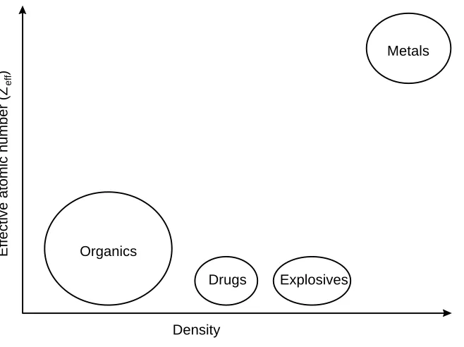
high density and low Zeff explosives can be identified. Figure 2.1 illustrates the density and
effective atomic number of materials of interest in luggage inspection systems. A system
that uses two x-ray energy levels for scanning is called a dual-energy system. Several
techniques exist for the collection of multi-energy images, including varying the input
energy of the x-ray source [EUR96], filtering the energy at the x-ray sensor [EIL92] and
using multiple sensors with different spectral responses [MIC93].
Yet another technique in x-ray imaging is to measure energy that is scattered due
to the Compton effect [FAI94]. Although some radiation penetrates the luggage in a
straight path and is measured by the transmission detector, some of the x-ray energy is
scattered either forward through the scanned object, or backwards, towards the x-ray
source. The images obtained by measuring scattered energy are called the forward scatter
and back scatter images. A single energy system using back scatter images for explosives
detection was developed by American Science and Engineering [SCH91].
Density
Effective atomic number (Z
eff
)
Explosives Drugs
Organics
[image:18.612.151.480.239.485.2]Metals
The prototype system discussed in this thesis is a true dual-energy system that
collects transmission and scatter images. The x-ray energy is varied by changing the input
energy to the x-ray tube, rather than filtering. The transmission images are used to obtain
an estimate of Zeff. Using both high and low energy images provides a more accurate
estimate of the effective atomic number. Density information is obtained using the
forward and back scatter images. Scatter energy provides more useful density information
than any transmission image. The relationship between measured energy and material
density is rather complicated and is analyzed in other literature [ARE96].
2.2 Sophisticated Commercial Luggage Inspection Systems
There are several luggage inspection systems available in the market. Some use
single energy, transmission images and are considered outdated. Others use advanced
scanning techniques and provide automated luggage inspection. These systems do not
require a human operator and are used in a number of airports today. Three of the more
sophisticated airport security systems are examined in this section.
2.2.1 Vivid Technologies
Vivid Technologies was formed in July 1989, following the explosion aboard
PanAm 103. The company specializes in airport security systems for luggage inspection.
The most sophisticated system manufactured by Vivid Technologies is Model VIS,
introduced in 1993 and intended for the inspection of checked luggage. The VIS is a
dual-energy system and uses a transmission detector for image collection. It can scan
900-1500 bags per hour without a human operator [VIV97].
To enhance the explosives detection capabilities of their systems, Vivid also offers
the Scatter Detection Enhancement (SDE) and SDE-2 modules. The SDE uses a forward
scatter detector, whereas the SDE-2 uses both a forward and back scatter detector. These
Vivid systems are not very widely used in the United States. Although they are
capable of detecting many types of explosives, they do not meet FAA requirements for
EDS certification.
2.2.2 American Science and Engineering
American Science and Engineering (AS&E) is the inventor of flying-spot x-ray
technology, which eliminates the need for an expensive sensor array by using a
concentrated beam of x-rays and a few large photo-multipliers for detection (see
Chapter 3). Most AS&E systems are equipped with scatter detectors and can collect
back scatter images. Forward scatter detectors are an option on a limited number of
systems. Using these technologies, high Z (metallics) and low Z (organics, plastics)
images are simultaneously presented to the operator to help identify attempts to conceal
dangerous substances [ASE96].
Using flying-spot technology, AS&E systems can obtain very high quality scatter
images. Most conventional x-ray scanning systems provide good quality transmission
images, but suffer from poor quality scatter images, yielding mediocre density estimations.
With good transmission and scatter quality, materials characterization can greatly be
improved, increasing the probability of detection and reducing the number of false alarms.
Despite the advantages of the flying-spot technology, it has been implemented on
only a small number of airport security systems, none of which provide automated
explosives detection. AS&E, the only flying-spot developer, concentrates on systems for
car and truck (cargo) search to identify illegal substances, and personnel inspection
systems, to detect weapons. Airline luggage presents a much different problem:
2.2.3 Invision Technologies
Invision is the developer of a very sophisticated, automated airport security
system, the CTX 5000. This system uses computed tomography (CT) and a rotating x-ray
source and detector pair to obtain a three-dimensional view of the luggage. The typical
two-dimensional x-ray view provides no depth information and can be confusing. The
operator can be mislead when certain objects are used to conceal explosives. By
presenting a three-dimensional view, however, luggage contents are easily identified and
any ambiguous overlap is detected. This assists the human operator and also improves the
detection probability of the explosives detection algorithm.
The CTX 5000 scans luggage using a single energy x-ray source and a
transmission detector, and presents the projected luggage view to the operator. Areas that
might contain explosives are identified by a red vertical line on the image. To further
analyze a region, the operator clicks on one of the lines. The x-ray source and detector
are then re-positioned and the luggage scanned at the location selected by the operator.
The cross sectional view at the plane of the red line is then presented on a separate
monitor. Explosives are painted in red, and explosive type and quantity information is
displayed [INV96].
The CTX 5000 is the only system certified by the Federal Aviation Administration
as an Explosives Detection System (EDS). However, its excellent detection capabilities
come at a very high price: a single unit currently sells for over $1,000,000. Furthermore,
although a throughput of 300 bags per hour is claimed, actual airport trials have averaged
100-150 bags per hour, causing concerns whether the system can be integrated into
airports without causing significant delays. The large size of the system (14 ft. long, 9,350
lbs) has also been a problem in placing it in already crowded airports. Finally, an operator
trained to detect explosives on a typical, two-dimensional system requires several months
2.3 Summary
Of the three major airport security system manufacturers, the Invision CTX 5000
is the only true EDS. Other systems provide a good solution for inspection of carry-on
luggage with the assistance of a human operator, but are not robust enough to become the
primary detection technology in airports. However, the CTX 5000, despite its excellent
capabilities, remains slow, big, and very expensive. Although many foreign airports are
subsidized by government grants and can afford a CTX 5000, in the United States airport
security systems are purchased by individual airlines. The high cost of the Invision system,
as well as the large number required to maintain a minimum luggage inspection rate, has
prevented most domestic carriers from using this system.
None of the systems available has explored the high quality forward and back
scatter images provided using the flying-spot technology for automated explosives
detection. Using both scatter measurements is significantly less expensive than a
computed tomography system, and may also provide a “smarter” system, with a higher
probability of explosives detection and a lower false alarm rate. This research project
provides an automated, multi-sensor and multi-energy prototype to assist in the
development of new algorithms for explosives detection. The combination of these
techniques and the new image processing software could pave the road to a new approach
Chapter 3. System Design
The purpose of this chapter is to describe the overall design of the AS&E 101ZZ
luggage inspection system, and the changes and additions made to the hardware for the
purpose of this research project. The type and positioning of the x-ray source and
detectors, the “flying-spot” technology, the detector pre-amplifier boards, as well as all the
computer controlled hardware are examined.
3.1 General Introduction
To develop new image processing algorithms for explosive detection in airport
luggage a system for exposing objects to x-ray radiation and collecting raw images is
necessary. The Federal Aviation Administration requested that the prototype be based on
the American Science and Engineering 101ZZ system. This system was chosen because of
its transmission and scatter collection capabilities, and also to further explore the
applications of flying-spot x-ray technology (see Section 3.2.2) in automated explosives
detection for airport luggage.
The hardware delivered to Virginia Tech was an early version of the 101ZZ. The
system electronics cabinet contained an outdated 8086 PC motherboard. The data
collection activity was controlled through an array of special purpose ISA hardware, some
of which were on wire-wrap, rather than printed circuit boards. No technical or other
documentation was provided about this specialized hardware. The images collected by the
system were of low resolution and rather poor quality, with obvious vertical striping.
There was no method of collecting raw, uncompensated images from the x-ray detectors,
and the nature of the image processing filters applied to the data remained unknown.. The
system provided no features for automatic control, and most system components had to be
accessed manually from the operator console. Furthermore, the system computer
The decision was therefore made to completely bypass the majority of the system
electronics and develop hardware and software to control the collection sequence, obtain
x-ray images and transfer them to a PC for processing. This new hardware provides high
resolution, high quality images that can be transferred to the PC either raw or after some
simple image processing filters. The thorough hardware documentation provided in this
thesis can be consulted to correct any system failures. If the original 101ZZ electronics
were used, determining the cause of any hardware problems and correcting them would be
an extremely difficult and time-consuming task. Bypassing the system electronics also
allows modification of other system components to eliminate the need for an operator
control panel and to completely automate the collection sequence through a personal
computer. Finally, the custom software integrates the new hardware with the existing
system, simplifies system control and provides an intuitive graphical user interface that
minimizes the chance of operator error.
Data is collected from the 101ZZ using the AS&E digitizing pre-amplifier boards.
These boards convert the analog x-ray detector signal to digital format, perform some
primitive processing, and transmit the output value over a differential pair bus. The
original digitizing boards were retained because they are simple in operation and could be
easily analyzed, and also because they are controlled completely through external signals
and operate autonomously without affecting other system components. Re-using the
digitizing hardware reduced development time and cost.
To control the AS&E pre-amplifier boards and retrieve image information, a
Differential Pair Interface Board (DPIB) was designed for the ISA bus. The DPIB uses a
Field Programmable Gate Array (FPGA) chip for re-configurable computing. The FPGA
can be dynamically re-programmed by the host computer, making the DPIB a general
purpose data collection and processing hardware, rather than restricting it to the AS&E
system application. The DPIB is paired with the Multiple Channel PCI board (MCPCI)
real-time data collection. The MCPCI also uses a FPGA for added versatility. Development
of the DPIB is analyzed in Chapter 4.
Other 101ZZ components that are also used in the prototype include the conveyor
belt motor, the infrared luggage sensors, and the x-ray controller, source and detectors.
Some modifications, which are explained later in this chapter, were performed to these
components to make them computer controllable. A retractable copper filter was added
to the system to filter the output energy at the x-ray source, as is discussed in
Section 3.3.4.
The prototype system is controlled by a Dell Optiplex P120 PC, running Windows
NT Workstation 4.0. This PC hosts the DPIB and MCPCI, and also interfaces to every
system component either through the DPIB (conveyor belt, infrared sensors), or through a
serial communications port (x-ray controller, copper filter motor). Software was
developed to control and automate the data collection sequence, interface with the
explosives detection algorithms and present the results to the system operator. Device
drivers were also developed to access the custom hardware (DPIB and MCPCI) under
Windows NT. The software development is discussed in Chapter 5.
3.2 AS&E System Design
The 101ZZ resembles a typical airport security system. It uses a conveyor belt for
the transport of luggage, and two black and white monitors to display the resultant
images. Most functions are available through the operator control panel: conveyor
direction control, x-ray power switch, and simple image processing functions, such as
invert and zoom. The system is controlled through an 8086 computer, enclosed in the
system electronics cabinet. All data collection and processing boards reside on the ISA
bus of the host computer. A keyboard and CGA monitor connector are available for
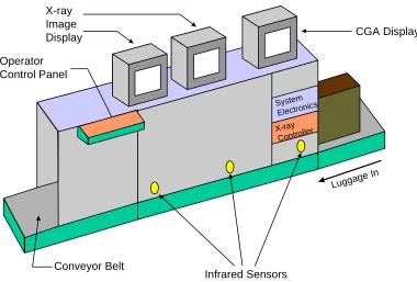
retrieve images. The original configuration of the AS&E 101ZZ system is illustrated in
Figure 3.1.
The AS&E system was originally equipped with two x-ray sources, one for each
side of the luggage. The first x-ray source is used to collect a transmission and back
scatter image for one side of the bag. The other is used to collect only a back scatter
image of the other side of the bag, to assist in overlapped object resolution.
The AS&E system is also equipped with three infrared beam break sensors, used
to detect the presence of luggage. The sensors are positioned in the front, middle and rear
of the tunnel. The conveyor belt and x-ray source are continuously turned on, and
collection begins when either the front or rear sensor is broken. The conveyor belt can be
controlled only from the operator panel. The x-ray source controls are found on a separate
panel, directly underneath the system electronics housing. Data collection with the 101ZZ
Infrared Sensors Conveyor Belt
X-ray Image
Display CGA Display
Operator Control Panel
Luggage In
System Electronics X-ray
Controller
3.2.1 X-ray source and detector positioning
The materials characterization algorithms developed for this project only require
image information from a single x-ray source. The second source, used to collect only
back scatter information, was removed. The back scatter detectors from the obsolete
source were then placed directly in front of the transmission detector, in order to
investigate forward scatter images. The digitizing board was connected to the new
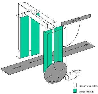
forward scatter detector. Figure 3.2 illustrates the current placement of the x-ray source
and the sensing elements.
scatter detectors transmission detector
conveyor
copper filter
x-ray tube
[image:27.612.128.474.279.608.2]chopper wheel
3.2.2 Flying-spot technology
An x-ray source, much like any radiation source, generates a field of energy, rather
than a concentrated beam or plane. Most systems utilize a slit collimator to restrict the
output to a narrow plane of radiation. The collimator is commonly made of lead or
another shielding material, with a narrow vertical slit through which x-rays can pass. Only
a small portion of the luggage is viewed at a time; the collimator effectively partitions the
luggage into smaller vertical regions, or scan lines. An array of sensing elements is then
used to sub-divide the exposed region into smaller parts and effectively generate a
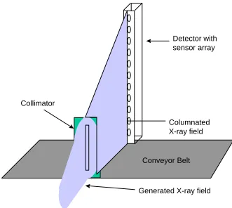
pixelated image. This configuration is shown in Figure 3.3. Using this approach, the
vertical image resolution is limited to the number of sensing elements in the array, whereas
the horizontal resolution can be controlled by varying the conveyor belt speed. Moreover,
the large number of sensors in the detector significantly increases overall system cost.
Detector with sensor array
Generated X-ray field Collimator
Columnated X-ray field
[image:28.612.138.469.353.649.2]Conveyor Belt
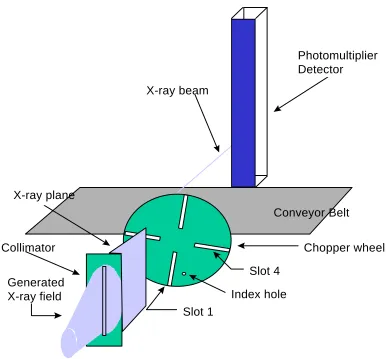
American Science & Engineering has developed a different, more flexible approach
to sampling the exposed object at discrete points. In addition to the collimator, a chopper
wheel fabricated of shielding material, is inserted in the x-ray path. The wheel has four
narrow slots and rotates at a constant speed. The effect of the wheel is to block the
collimated x-ray plane and create a narrow beam. As the wheel turns, the beam moves
from bottom to top, scanning an entire vertical line. The movement of the beam creates a
pixelated image, eliminating the expensive sensor array. Instead, a few large
[image:29.612.114.500.281.640.2]photo-multiplier tubes are used. The operation of the flying-spot technology is shown in
Figure 3.4. Using a traveling beam allows control of both the horizontal and vertical
resolution, and reduces system cost by using a less expensive detector element.
Conveyor Belt Photomultiplier Detector
Index hole Slot 4
Slot 1 X-ray beam
Chopper wheel X-ray plane
Collimator
Generated X-ray field
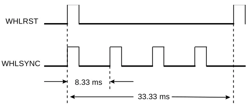
To synchronize data collection with the position of the chopper wheel, two pairs of
incandescent lamps and photo-transistors are used. One pair is aligned with an index hole
on the chopper wheel (see Figure 3.4) and is used to identify Slot 1. A WHLRST (wheel
reset) pulse is generated by the chopper wheel logic when Slot 1 enters the field of view.
The other lamp-transistor pair is aligned to indicate when any of the four slots enters the
field of view and generates a WHLSYNC (wheel reset, also SLOTSYNC) pulse. Since
there are four chopper wheel slots, four WHLSYNC pulses are generated for every
WHLRST pulse. The chopper wheel rotates at 1800 RPM, generating the signals shown
in Figure 3.5. WHLSYNC indicates when the x-ray beam is at the lowest point of its
path, and is used to start the collection of a new line. WHLRST is used to start a new
frame, an operation that is further explained in Chapter 4.
3.2.3 Digitizing pre-amplifier boards
The signal obtained from the x-ray detectors is analog in nature and must be
converted to a digital value for image processing. The conversion process, as well as a
very primitive shading correction operation, is performed on the AS&E pre-amplifier
boards. Each x-ray detector uses a separate pre-amplifier board. These boards require
external control and contain no “intelligent” hardware, such as a micro-controller.
The data and control bus of the pre-amplifier boards are accessible through a 50-8.33 ms
33.33 ms WHLSYNC
[image:30.612.181.437.325.434.2]WHLRST
header. These signals make up the Data and Control Interface (DCI) of the pre-amplifier
boards. The DCI uses differential pair signals.
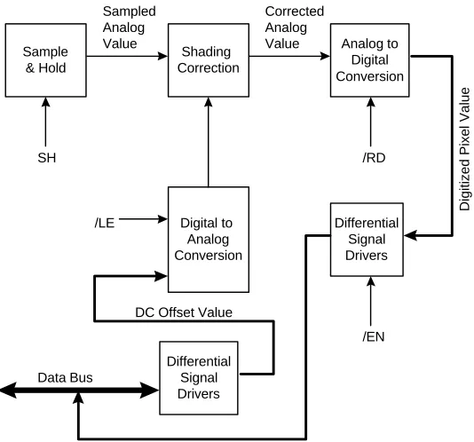
The block diagram of the digitizing boards is shown in Figure 3.6. The incoming
analog signal first passes through sample and hold circuitry, which stores the current
analog pixel value. Shading correction follows. There, a DC offset is added to the analog
value. The purpose of this process is to correct for the non-linearity and slight geometrical
imperfections of the chopper wheel slots, allowing uniform image quality. A narrower
slot reduces the x-ray energy projected on the object and results in slightly darker pixel
values. Images that are not shade compensated contain visible vertical striping. The
shade compensation value for a pixel is placed on the DCI data bus by the external
hardware. A digital-to-analog converter is then used to convert the digital value to an
analog offset that is added to the sample-and-hold output.
Sample & Hold
SH
Shading Correction
/LE
Analog to Digital Conversion
/RD
Digital to Analog Conversion
Differential Signal Drivers
Differential Signal Drivers
/EN Sampled
Analog Value
Corrected Analog Value
Digitized Pixel Value
DC Offset Value
[image:31.612.168.435.372.621.2]Data Bus
The compensated value is then digitized by a digital-to-analog converter. The
output of the converter connects to a set of differential pair drivers for output on the DCI.
The drivers can either operate in high-impedance mode (while the pre-amplifier boards
read the shade compensation value from the DCI), or in output mode. The direction of
the data bus is controlled through an external control signal. An external pulse is also
used to initiate the conversion process.
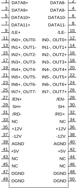
Figure 3.7 shows the signal assignment on the DCI. The polarity of the incoming
and outgoing data bus signals is reversed, per AS&E convention.
[image:32.612.238.373.294.621.2]DATA8+ DATA9+ DATA10+ DATA11+ /LE+ IN0+, OUT0-IN2+, OUT2-IN1+, OUT1-IN3+, OUT3-IN4+, OUT4-IN6+, OUT6-IN5+, OUT5-IN7+, OUT7-SH+ /EN+ /RD- DATA8- DATA9- DATA10- DATA11- /LE-IN0-, OUT0+ IN2-, OUT2+ IN1-, OUT1+ IN3-, OUT3+ IN4-, OUT4+ IN6-, OUT6+ IN5-, OUT5+ IN7-, OUT7+ SH- /EN-/RD+ 1 2 3 5 7 9 11 13 15 17 19 21 23 25 27 29 31 33 35 37 39 12 14 16 18 20 22 24 26 28 30 32 34 36 38 40 4 6 8 10 NC +12V -12V AGND NC +12V -12V AGND 41 +5V 43 NC 45 NC 47 DGND 49 DGND 42 44 46 48 +5V NC NC DGND 50 DGND
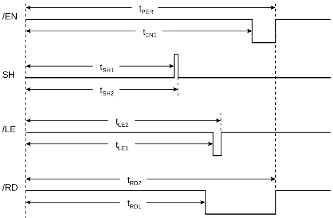
There are four control signals on the DCI that fully control the circuitry on the
digitizing boards. These are as follows:
• /EN: used to determine the direction of the differential pair data bus.
When high, the pre-amp board is in input mode and the shade compensation
value should be available on the bus. When low, the drivers are enabled, and
the digitized pixel value is placed on the data bus [MOT93].
• SH: gate pulse for the sample and hold circuitry. The incoming analog
value from the x-ray source is sampled on the rising edge of this pulse.
• /LE: latches the data compensation value on the data bus into the
digital-to-analog converter. This value is used to generate the offset added to analog
x-ray detector signal.
• /RD: controls the conversion process on the digital-to-analog converter.
The conversion is started on the falling edge of this pulse. After completion of
the process, the output of the DAC remains constant only while this signal is
low. The DAC output is placed in high-impedance mode when this signal is
high [ANA91].
The waveforms generated by the AS&E system electronics are shown in
Figure 3.8. The timing values for a vertical resolution of 128 pixels are shown in
Table 3.1 AS&E system timing values
tPER
tEN1
tSH1
tSH2
tLE2
tLE1
tRD2
tRD1
/EN
SH
/LE
[image:34.612.247.368.439.628.2]/RD
Figure 3.8 AS&E pre-amplifier board waveform
Variable Time (µµs)
tPER 53.62
tEN1 53.28
tSH1 45.89
tSH2 46.32
tLE1 47.78
tLE2 49.99
tRD1 46.94
3.3 System Components
3.3.1 X-ray source controller
The prototype system is intended to collect image data at multiple energy levels.
Therefore, computer control of source settings, such as x-ray voltage and current, is
necessary. The AS&E 101ZZ system is equipped with a Gemini 2000 x-ray controller,
manufactured by Gulmay, Inc. The controller features an operator panel, where system
settings can be changed, and an RS-232 serial port for data communications. A
comprehensive set of codes to either transmit commands or request system information is
provided [GUL95]. These commands are summarized in Table 3.2 and Table 3.3.
Table 3.2 x-ray controller request codes
All requests codes use a single character, followed by a carriage return. The result
is usually a question mark, followed by the same character, and then a three digit number.
The voltage, current, and time requests return the corresponding value of the x-ray
settings. The mode command, used to determine the state of the source, returns one of
the following values:
• 000: Key is in position 2, x-ray source can not be turned on
• 001: x-ray off
• 002: x-ray warming up
• 003: x-ray switching on or off.
• 004: x-ray on.
Command Description
?V X-ray voltage. Responds ?Vnnn<CR>
?I X-ray current. Responds ?Innn<CR>
?T Elapsed time. Responds ?Tnnn<CR>
Commands consist of a exclamation point, then a one character code, and are
terminated by a carriage return. A three digit numerical value is used with some
commands and follows the character code.
Table 3.3 x-ray controller command codes
3.3.2 Infrared luggage sensor
Imperative to a completely automated system is a sensor that can report the
position of the luggage in the x-ray tunnel. This information can be used to enable and
disable image collection, and also to turn the x-ray source on when luggage is present, and
off when the tunnel is empty.
The prototype system uses two of the three infrared beam break devices, located at
the front and rear of the tunnel. These devices are powered by the AS&E system and
return a binary value. A value of one (high) indicates that the path is clear, whereas a
value of zero (low) is returned when the beam path is broken.
3.3.3 Conveyor belt
Luggage is commonly transported by means of a conveyor belt. The AS&E
system is equipped with such a belt, a motor and a motor controller. However, the system
Command Description
!V Set voltage. Format: !Vnnn<CR>
!I Set current. Format: !Innn<CR>
!T Reset timer
!X Turn x-ray on.
motor controller could only be controlled through the operator control panel and provided
no data interface for computer control.
To allow for automatic control of the belt, the motor controller was modified. The
controller uses two lines for conveyor operation. If both lines are open, the conveyor is
stopped. By shorting one of the two lines, the conveyor can move in either the forward or
reverse direction. For the prototype system, these lines were interrupted and a relay
inserted in the current path. The relays are controlled by the DPIB and determine the
on-off state and direction of the belt. There is still no control of the motor speed, unless the
setting is altered on the motor controller housing.
3.3.4 Copper Filter
As discussed previously, the prototype system scans luggage at high and low x-ray
energy settings. The energy level of the output photons, however, is not limited to the
input energy, but is distributed over a range of frequencies. There is also significant
overlap between the low and high energy spectral distributions, and the total output
energy at 150 KV is much higher than at 80 KV, as shown by Xinhua Shi [DRA97a]. For
materials characterization purposes, it is desirable to minimize the overlap region between
the two energy spectrums and balance the total output energy. To achieve this, a copper
filter was added to the system, as shown in Figure 3.2. The filter is inserted only during
high-energy collection, and is removed at all other times. The subsystem was designed by
Jinhuo Shan, using a Velmex 8300 series stepper motor driver [VEL85]. The filter is
attached to the cylindrical motor mount, and can be rotated between the fully removed and
fully inserted position. Protection switches are installed on the assembly to prevent motor
damage if rotation is attempted outside the system boundaries.
The motor controller can be accessed either through the external control panel, or
an RS-232 serial port. The controller uses a BASIC interpreter to accept and run simple
through the serial port and then executed. The motor then awaits a numerical value
(followed by a line feed character), and moves the motor to the absolute angle designated
by the input value. The origin point (position of angle 0), is the filter position at the time
the controller code is executed.
3.4 Workstation Setup
The outdated 101ZZ host computer was replaced by a high performance personal
computer to reduce algorithm execution times and provide computer control of all the
prototype system components. The PC is equipped with a high resolution monitor and
video adapter to display the processed results to the system operator. The new computer
is used to control the system hardware, collect data through the custom hardware boards
(DPIB and MCPCI), process the x-ray images, and display the output. If explosives are
detected in the luggage, they are highlighted in the output image and an alarm is sounded.
A Dell Optiplex P120, running the Windows NT 4.0 Workstation operating system
is used. Windows NT was chosen for its reliability, availability and low cost. The
multi-processor capabilities of this operating system are also very important as plans exist to
move to a dual or even quad CPU system. The current image processing algorithms and
software structure support a high degree of parallelism. Moving to a symmetric
multiprocessing system will significantly reduce the time required to scan and process a
bag.
The PC hosts the DPIB and MCPCI boards. The DPIB resides on the ISA bus,
whereas the MCPCI uses the PCI bus for high speed transfers. Both devices are
controlled by the system software through devices drivers developed specifically for these
boards. The development of these drivers is discussed in Chapter 5. The DPIB is used to
interface to the AS&E pre-amplifier boards and collect image data. It is also used to
All system automation is controlled by the graphical user interface, Galaxie. This
program controls the high and low energy collection sequence, interfaces to the image
processing and materials characterization programs, and outputs the processed data to the
operator, producing an alarm if dangerous substances are detected. The software
Chapter 4. DPIB Hardware
The purpose of this chapter is to describe the hardware structure of the Differential
Pair Interface Board. The DPIB is described at the board level, analyzing the functionality
of each external functional block, and the logic level, describing the operation of each
module in the FPGA. The information in this chapter is intended to aid in the initial setup
and configuration of the DPIB by the end user, as well as a reference guide to a hardware
designer wishing to modify the internal logic. Although the discussion focuses on the
DPIB design for the x-ray imaging system, the re-configurable nature of the board
supports many data collection applications with minimal developer effort. The
re-configurability of the DPIB is explored in Section 4.4.
4.1 Design Overview
The decision to discard the AS&E system electronics created the need for the
development of new hardware to collect data from the AS&E pre-amplifier boards and
transfer the data to the PC. The new hardware must meet the following design
requirements:
• Collect data from three input sources. Differential pair signals, with a
bi-directional data bus, are required. The data interface should be based on the
AS&E system protocol to simplify connection to the pre-amplifier boards.
• Multiplex data. The three input sources must be combined on a single output
bus and transferred to the PC.
• Control system components. Access must be provided to the conveyor belt
motor controller, the infrared sensors, and any other system devices that will
be controlled by the host computer.
• Interface to the PC. This interface will be used to access I/O ports to control
• Programmability. Any system variables, such as timing signal parameters or
shading correction values, can be changed from the PC through IO ports.
• Flexibility. The hardware design, both at the board level and the logic level,
must be flexible and allow interfacing to other data sources, such as CCD or
linescan cameras. Designing a general purpose hardware device will increase
its applications and reduce development time and costs in other projects, by
eliminating the need to design specialized hardware.
To satisfy these requirements, the Differential Pair Interface Board (DPIB) was
created. The DPIB is designed to serve as a general purpose data collection device, as is
discussed in Section 4.4. It is based on a Xilinx XC4000 series Field Programmable Gate
Array (FPGA) chip. The FPGA can be re-programmed through the PC interface, allowing
the DPIB to be used for a variety of image processing and general data processing
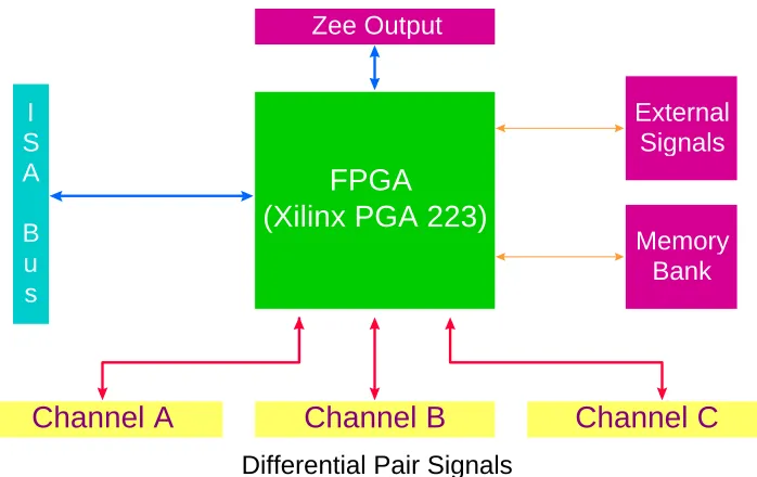
applications. The flexibility of the DPIB continues at the board level to simplify
[image:41.612.133.482.441.661.2]connection to different external data sources. A block diagram of the DPIB is shown in
Figure 4.1.
FPGA
(Xilinx PGA 223)
Channel A
Channel B
Channel C
Zee Output
Differential Pair Signals
I S A
B u s
Memory Bank External
Signals
The main processing unit of the DPIB is a Xilinx 4000 series FPGA. The FPGA is
a fully re-programmable computing resource consisting of Configurable Logic Blocks
(CLBs) and routing resources to connect the CLBs. The number of CLBs and their
propagation delay is determined by the family type, size and speed rating FPGA.
Each CLB uses two independent function generators (FG) to implement any
Boolean function of four variables. A third 3-input function generator is used to combine
the outputs of the two FGs with a third input from outside the CLB. Two edge-triggered
D-type flip-flops with a clock enable are also used as storage elements. The flip-flops can
be programmed to operate in synchronous or asynchronous mode and can be triggered on
either the rising or falling clock edge.
The DPIB uses a 223-pin PGA socket that can accept most FPGA chips in the
XC4000 family. The size and speed rating used on the DPIB is determined by the specific
application, rather than the architecture of the board. Smaller designs can use a slower,
smaller FPGA (such as the XC4005H), whereas large designs, such as the current AS&E
system design use larger, more expensive chips (XC4013). Table 4.1 lists some FPGA
chips that are compatible with the DPIB and their characteristics [XIL94a], [XIL94b].
Table 4.1 XC4000 Family FPGA chips accepted on the DPIB
FPGA type CLBs available Equivalent
Gates
Price
XC4005H 196 5,000 $266
XC4010E 400 10,000 $203
XC4013E 576 13,000 $393
Communication with the external data sources is accomplished through the
differential pair channels. A 12-bit bi-directional bus and four output only control signals
are provided on each channel connector. The specific function of each pin on these
connectors is determined by the FPGA program and can be changed depending on the
current application. Also available on the DPIB are a memory bank for data storage and
an external signal interface. The latter provides access to TTL or other level signals that
can not be connected through the differential pair interface. Finally, the ISA interface
connects to the ISA bus of the host PC. It is used to upload the FPGA program during
initialization, or to communicate with FPGA I/O registers while the DPIB is in operation.
Image data can be transferred to the DPIB through this interface.
The Zee output connector is used to interface the DPIB to other image processing
hardware. The Zee bus was developed as a standard for inter-board communications by
Thomas Drayer and William King [DRA97b]. This bus can be used to connect the DPIB
to the MCPCI, for high-speed data transfers. The MCPCI accepts data from up to six
channels from a Zee connector. The data is de-multiplexed and then transferred to the
host PC using bus master direct memory access (DMA). The high throughput of the PCI
bus (up to 132 Mbytes/sec) [PCI93] compared to that of the ISA bus (up to 1 Mbyte/sec)
[EGG91] makes real-time system operation possible. The Zee output connector can also
be used to interface the DPIB to the MORRPH board (MOdular Re-programmable
Real-time Processing Hardware) [DRA97a]. The MORRPH is a general purpose, FPGA based
processing unit intended for real-time image processing. It can be used with the DPIB and
MCPCI in a variety of applications requiring real-time performance to collect data from
4.2 Board Level Description
The structure of the DPIB may be divided into the following functional blocks:
a) data interface, which connects to the input data source, such as the
AS&E pre-amplifier boards,
b) Zee bus interface, which allows data processed by the DPIB to be
transferred to another device (MCPCI, MORRPH) for further
processing,
c) ISA interface, which provides communication with the host PC during
and after initialization of the hardware,
d) sensor signal interface, which makes external control signals available
to the DPIB, and
e) memory bank, which is used to store data compensation values for the
shading correction circuitry.
Each of these interfaces is discussed in further detail. A component location
diagram identifying the location of each connector and integrated circuit in the DPIB is
provided in Appendix A. The board level schematics of the DPIB are also included in
Appendix A.
The DPIB currently uses a 14.318MHz oscillator for the FPGA. The clock
frequency is determined by the FPGA speed and program, and can easily be changed by
inserting a new oscillator in the socket.
4.2.1 Data Interface
The data interface is a bi-directional data and control signal bus used to connect to
the image data source. The bus was designed using the AS&E pre-amplifier bus protocol
as a guide, although certain extensions have been made to allow for a wider variety of
A total of twelve data bits and four control bits are available on each data interface
connector (J1, J2, and J3). The bi-directional data bus is used to receive image data and
transmit shading correction coefficients. A set of three DS26LS31 drivers and three
DS26LS32 receivers is used to convert between TTL level signals used on the DPIB and
RS-422 level signals used on each connector. When not used, the drivers are placed in
high impedance mode to prevent bus contention with the AS&E hardware. It should be
noted that, although the DPIB is configured for twelve bit operation, the current AS&E
system configuration can only accept eight bit data. The four higher order bits have been
used with other input data sources, such as B&W cameras.
The control bus is a unidirectional output bus. A single DS26LS31 driver is used
for each group of control signals. The output enable pins of these drivers are hardwired
and can not be used to select high impedance mode.
A set of resistor network packs is used with each data bit to allow impedance
matching between the DPIB and the input data source. Some data sources require the use
of termination resistors for noise reduction and line balancing. The resistor SIPPS should
remain empty when using the AS&E system, since termination resistors are provided on
the sending end.
The data interface bus is physically available through a 50-pin polarized protected
header. The pin assignment for this connector is shown in Figure 4.2. The polarity of the
lower eight data bits, as well as the polarity of the control signals, is determined by the
AS&E protocol. The change in polarity in the /RD signal (pins 31 and 32) is not a
typographical mistake, but rather the choice made by AS&E in the pre-amplifier board
Figure 4.2 Data Interface Connector signal locations
4.2.2 Zee Bus Interface
The Zee bus was developed by Thomas Drayer and William King as a standard bus
for inter-board communication in an image processing system [DRA97b]. It is a
unidirectional, synchronous, 16-bit bus with an 8-bit data bus. The Zee bus connector on
the DPIB is used for communication with either the MCPCI board, to transfer image data
to the host PC via the PCI bus, or the MORRPH board, for real-time processing of the
data before transferring it to the PC. All Zee bus signals are buffered through two
74LS245 data buffers (U5 and U6).
The pinout of the 40-pin, polarized Zee bus connector (J4) is shown in Figure 4.3.
Pin Name Function
DATA[11:0] Data Bus
/LE Latch enable
/EN Driver Enable
SH Sample & Hold
/RD Convert
NC No Connection
used for synchronization and transfer of Zee bus commands. All signals are valid during
the high portion of the clock. The channel select bits, CSEL[0:2], are used to determine
which channel is currently being transferred. The command bits, CMD[0:2], are used to
indicate a line start, a line end, or a marking cycle (a cycle during which nothing happens,
there is no valid data on the bus, nor is a Zee command being issued). Finally, the DV bit
is used to indicate valid data. The data bus should be sampled only when DV is high.
Zee Bus commands used
Figure 4.3 Zee bus signal locations and commands
4.2.3 ISA Interface
The ISA interface is used during initialization to program the Xilinx FPGA, but
also while in operation, to access registers connected to the luggage sensors and the
conveyor belt motor. The interface is based on an Altera EP324 EPLD and was
developed by William King for use on the MORRPH-ISA board. It has been modified by
the author to use the IORDY signal on the ISA bus [EGG91]. It was experimentally
observed that on some faster motherboards FPGA programming would occasionally fail.
The timing of two consecutive ISA write cycles is faster than the time required for an
DATA0 DATA2 DATA1 DATA3 DATA4 DATA6 DATA5 DATA7 1 2 3 4 5 10 11 12 13 14 15 16 17 18 19 20 26 27 28 29 30 31 32 33 34 35 36 37 38 39 40 22 23 24 25 21 6 7 8 9 CLOCK CSEL1 CSEL0 CSEL2 CMD0 CMD2 CMD1 DV NC NC NC NC GND GND GND GND GND GND GND GND GND GND GND GND GND GND GND GND GND GND GND GND
if DV = 0
CMD = 000 marking cycle
CMD = 010 line start
CMD = 011 line end
If DV = 1
CMD = 100 valid 1 byte data
FPGA cell to be programmed and would result in data loss. By connecting the
RDY/BUSY line of the FPGA to the ISA IORDY signal, bus activity is suspended until
the FPGA cell has been programmed.
The ISA interface provides access to the DPIB through three consecutive ISA
ports: the address port, data port, and the program port. The address port holds the
address of the DPIB register to be accessed. The lower five bits of the address port are
used, allowing access to a total of 32 registers on the FPGA. The data port is used to
hold the data written to or read from the DPIB register. Finally, a write to the program
port selects the re-program line on the FPGA. This erases the current FPGA
configuration and prepares it to be re-programmed, possibly for a different application.
The operation of the ISA interface is summarized in Table 4.2 below. The ISA base
address of the DPIB is determined by the EPLD and can not be changed, unless a new
EPLD is used. The current base address is set at 0x0304.
Table 4.2 ISA Interface port description
To properly control the DPIB, the desired FPGA port address must first be written
to the address port, regardless of whether a read or write operation will be performed.
The ISA interface then performs a mapping of the contents of the address port to the
address select lines of the FPGA. The programmer can access the FPGA port by either
reading from the data port, which will return the data contained in the FPGA, or writing to
the data port, which will transfer the data to the FPGA register. Any port operation,
Port Offset from base ISA Description
address (W) 0 Address of FPGA port to access, only lower 5 bits are
used
data (RW) 1 Data read from or written to port
therefore, will take two ISA cycles to complete: a mandatory write cycle, followed by a
read or write cycle.
4.2.4 Sensor Signal Interface
The Sensor Signal Interface (SSI) is used to control outside devices, such as the
conveyor belt, and return information to the DPIB, such as luggage sensor information, or
chopper wheel synchronization signals. The SSI uses a 9-pin female D-sub connector
(J5). The signal assignments on the connector are shown in Table 4.3.
All signals coming into the DPIB pass through a potentiometer and a 74LS245
buffer (U7) before entering the FPGA. The potentiometer is used to lower the voltage of
certain incoming signals (such as the chopper wheel synchronization pulses) to appropriate
TTL levels. Any signals exiting the DPIB, such as the conveyor belt control signals, pass
[image:49.612.204.409.452.656.2]through