Linskens HF and Jackson JF (1991) Essential Oils &Waxes. Berlin: Springer-Verlag.
Recent Trends in Flavour Evaluation of Spices Newer Trends in Essential Oils and Flavours (1991) New Delhi, India: Tata MacGraw-Hill Publishing Co.
Svendsen and Scheffer (1985)Essential Oils and Aromatic Plants. Dordrecht, The Netherlands: Junk Publishers. Sweig G and Sherma J (1984)CRC Handbook of
Chromato-graphy,Terpenoids, vol. 1. Boca Raton, Florida: CRC Press Inc.
THERMALLY-COUPLED COLUMNS:
DISTILLATION
R. Smith, Centre for Process Integration, UMIST, Manchester, UK
Copyright^ 2000 Academic Press
Introduction
A considerable amount of energy is used in distil-lation operations. Energy integration has proven to be successful in reducing energy costs for conven-tional distillation arrangements. However, the scope for energy integration of conventional distilla-tion columns into an overall process is often limited. Also, practical constraints often prevent integra-tion of distillaintegra-tion columns with the rest of the process.
If the column cannot be integrated with the rest of the process or, if the potential for heat integration is limited by the heatSows in the background process, then we must turn our attention back to the distilla-tion operadistilla-tion itself and look at unconvendistilla-tional arrangements.
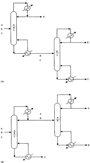
Figure 1shows two conventional arrangements for the separation of a three-component mixture. The sequence shown in Figure 1A is the so-called direct sequence, in which the lightest component is taken overhead in each column. The indirect sequence shown in Figure 1B takes the heaviest component as bottom product in each column.
One of the most signiRcant unconventional ar-rangements involves thermal coupling. Figure 2 shows a number of unconventional arrangements that use thermal coupling. In thermal coupling part of the heat transfer necessary for the separation is pro-vided by direct contact via materialSows. Figure 2A shows a side-rectiRer arrangement and Figure 2B a side-stripper arrangement. Arrangements similar to that in Figure 2B are widely used in petroleum reR n-ing. The fully thermally coupled arrangement in Figure 2C (sometimes known as the Petlyuk column) has been known for over 50 years. Various studies have shown that thermally coupled arrangements can
save up to 30% of energy costs when compared with conventional arrangements.
Simple Versus Complex Columns
ConsiderRrst the design of distillation systems com-prising only simple columns. These simple columns employ:
E one feed split into two products;
E key components which are adjacent in volatility;
E a reboiler and a condenser.
For a three-component mixture in which simple col-umns are employed, the decision is between the two sequences illustrated in Figure 1.
Consider theRrst characteristic of simple columns, which involves a single feed being split into two products. As aRrst option to two simple columns, the possibilities shown inFigure 3can be considered, in which three products are taken from one column. The designs can be both feasible and cost-effective when compared with simple arrangements, but only for certain conditions. If the feed is dominated by the middle product (typically more than 50% of the feed) and the heaviest product is present in small quantities (typically less than 5%) then the arrangement shown in Figure 3A can be an attractive option. If a pure middle product is required, then it is usually only possible if there is a large volatility difference be-tween components B and C, with the middle product taken as a vapour to assist the separation. The heavy product mustRnd its way down the column past the side-stream. Unless the heavy product has a small
Sow and the middle product a highSow, a reasonably pure middle product cannot be achieved.
If the feed is dominated by the middle product (typically more than 50%) and the lightest product is present in small quantities (typically less than 5%), then the arrangement shown in Figure 3B can be an attractive option. This time the light product must
Rnd its way up the column past the side-stream. If
Figure 1 The (A) direct and (B) indirect sequences of simple distillation columns for a three-component separation. (Reproduced with permission from Triantafyllou and Smith (1992)Transactions of the Institution of Chemical Engineers, Part A 70: 1992.)
a pure middle product is required, then it is usually only possible if there is a large volatility difference between components A and B, with the middle prod-uct taken as a liquid to assist the separation.
In summary, single-column side-stream arrange-ments can be attractive when the middle product is in excess and one of the other components is present in only minor quantities. Thus, the side-stream column
Figure 2 Thermally coupled columns. (A) Side-rectifier; (B) side-stripper; (C) fully thermally coupled column. (Reproduced with permission from Triantafyllou and Smith (1992)Transactions of the Institution of Chemical Engineers, Part A 70, 118.)
Figure 3 Distillation columns with three products. (A) More than 50%middle component and less than 5%heaviest compo-nent; (B) more than 50%middle component and less than 5% lightest component. (From Smith and Linnhoff (1988)Chemical Engineering Research and Design, 66, 195, reproduced with permission from the Institution of Chemical Engineers.)
only applies to special feed compositions. More gen-erally applicable arrangements are possible by relax-ing the restriction that separations must be between adjacent key components.
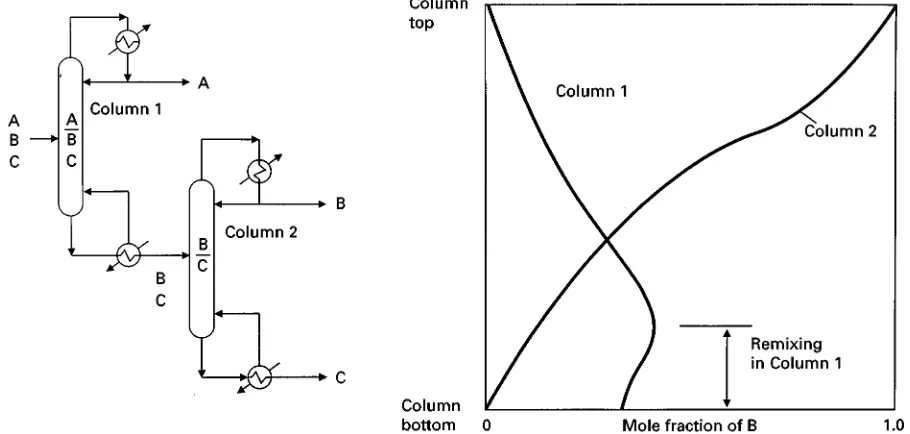
[image:3.568.59.272.295.644.2]Consider a three-product separation as shown in Figure 4Ain which the lightest and heaviest compo-nents are chosen to be the key separation in theRrst column. In such a case, two further columns are required to produce pure products. However, note that the bottoms and overheads of the second and third columns in Figure 4A are both pure B. Hence the second and third columns could simply be con-nected and product B taken as a side-stream, as shown in Figure 4B. The arrangement in Figure 4B is known as a prefractionator arrangement. Note that theRrst column in Figure 4B, the prefractionator, has a partial condenser to reduce the overall energy con-sumption. The prefractionator arrangement in Figure 4B typically requires 30% less energy than conventional arrangements for the same separation duty. The extent of the energy saving depends on the feed composition and the relative volatility of the components being separated. The energy saving re-sults from the fact that the prefractionator arrange-ment is thermodynamically more efRcient than a simple arrangement.
To understand why this is the case, consider the sequence of simple columns shown inFigure 5. In the direct sequence shown in Figure 5, the composition of component B in theRrst column increases below the feed as the more volatile component A decreases. However, moving further down the column, the com-position of B decreases again as the comcom-position of the less volatile component C increases. Thus, the composition of B reaches a peak, only to be remixed.
Figure 4 Choosing nonadjacent keys leads to the prefractionator arrangement. (A) Sequence for three product separation using nonadjacent keys; (B) prefractionator arrangement. (Reproduced with permission from Smith (1995) Chemical Process Design, McGraw-Hill.)
Figure 5 Composition profiles for the middle product in the columns of the direct sequence show remixing effects. (From Triantafyllou and Smith (1992)Transactions of the Institution of Chemical Engineers, Part A 70, 118, reproduced by permission of the Institution of Chemical Engineers.)
Similarly, with the Rrst column in the indirect se-quence, the composition of B Rrst increases above the feed and reaches a maximum only to decrease as
the more volatile component A increases. Again, the composition of B reaches a peak, only to be remixed.
[image:4.568.58.513.457.674.2]Figure 6 Composition profiles for the middle product in the prefractionator arrangement show that there are no remixing effects. (From Triantafyllou and Smith (1992)Transactions of the Institution of Chemical Engineers, Part A 70, 118, reproduced by permission of the Institution of Chemical Engineers.)
This remixing which occurs in both sequences of simple distillation columns is a source of inefRciency in the separation. By contrast, consider the prefrac-tionator arrangement shown in Figure 6. In the pre-fractionator, a crude split is performed so that component B is distributed between the top and bot-tom of the column. The upper section of the prefrac-tionator separates AB from C, whilst the lower section separates BC from A. Thus, both sections remove only one component from the product of that column section and this is also true for all sections of the main column. In this way, the remixing effects which are a feature of both simple column sequences are avoided.
In addition, one other feature of the prefrac-tionator arrangement is important in reducing mixing effects. Losses occur in distillation operations due to mismatches between the composition of the column feed and the composition on the feed tray. Because the prefractionator distributes B between top and bottom, this allows greater freedom to match the feed composition with one of the trays in the column to reduce mixing losses at the feed tray.
Distillation Using Thermal Coupling
Rather than each column having a reboiler and con-denser, it is possible to use materialSows to provide some of the necessary heat transfer by direct-contact thermal coupling.
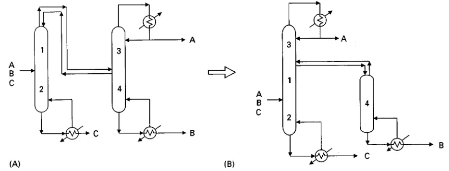
First consider thermal coupling of the simple se-quences from Figure 1.Figure 7Ashows a thermally coupled direct sequence in which the reboiler of the
Rrst column is replaced by thermal coupling. Liquid from the bottom of theRrst column is transferred to the second as before, but now the reboiler of the second column supplies the vapour required by the
Rrst column. The four column sections marked as 1, 2, 3 and 4 in Figure 7A can be rearranged to form a side-rectiRer arrangement, as shown in Figure 7B.
Similarly, Figure 8A shows a thermally coupled indirect sequence in which the condenser of theRrst column is replaced by thermal coupling. The four column sections marked as 1, 2, 3 and 4 in Figure 8A can again be rearranged, but this time forming a side-stripper arrangement.
Both the side-rectiRer and side-stripper arrange-ments have been shown to reduce the energy con-sumption compared with simple two-column arrangements. This results from reduced mixing losses in the Rrst (main) column. As with the Rrst column of the simple sequence, a peak in composition occurs with the middle product, but now advantage of the peak is taken by transferring material to the side-rectiRer or side-stripper.
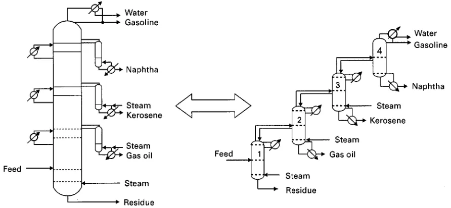
Side-stripper arrangements are commonly used in petroleum reRnery separations. Figure 9A shows a typical arrangement for distillation of crude oil. The main column is fed with the pre-heated crude oil feed. Products are taken from various points from the main
Figure 7 Thermal coupling of the direct sequence. (A) Thermally coupled direct sequence; (B) side-rectifier arrangement. (Repro-duced with permission from Smith (1995)Chemical Process Design, McGraw-Hill.)
Figure 8 Thermal coupling of the indirect sequence. (A) Thermally coupled indirect sequence; (B) side-stripper arrangement. (Reproduced with permission from Smith (1995)Chemical Process Design, McGraw-Hill.)
column via side-stripper columns. Heat is also re-moved at various points through the main column via pumparounds. Pumparounds take liquid from the column, cool it and return it to the column at a higher point, effectively acting as intermediate condensers. Heat to the side-strippers is supplied from either reboilers or live steam injection. The arrangement shown in Figure 9A is equivalent to a sequence of simple columns in the indirect sequence, as shown in Figure 9B.
Consider now thermal coupling of the prefrac-tionator arrangement from Figure 10A. Figure 10B shows the equivalent thermally coupled prefrac-tionator arrangement, sometimes known as the Petlyuk column. To make the two arrangements in Figure 10 equivalent, the thermally coupled prefrac-tionator requires extra plates to substitute for the prefractionator condenser and reboiler.
[image:6.568.64.505.516.684.2]Various studies have shown that the thermally coupled arrangement in Figure 10B requires typically 30% less energy than a conventional arrangement using simple columns. The saving depends on the feed mixture. In most cases the fully thermally coupled column in Figure 10B requires less energy than the side-rectiRer and side-stripper arrangements, for the same separation. The prefractionator arrangement in Figure 10A and the thermally coupled prefrac-tionator (Petlyuk column) in Figure 10B are similar in terms of total heating and cooling duties, but there are differences in the temperatures at which the heat is supplied and rejected.
Figure 11 shows the evolution from the prefrac-tionator in Figure 11A to the thermally coupled pre-fractionator in Figure 11B. Finally, in Figure 11C, the thermally coupled prefractionator uses a single shell with a vertical bafSe dividing the central section
Figure 9 The typical crude oil distillation column decomposes to a sequence of simple columns in the indirect sequence.
Figure 10 Thermal coupling of the prefractionator arrangement. (A) Prefractionator; (B) thermally coupled prefractionator. (Repro-duced with permission from Smith (1995)Chemical Process Design, McGraw-Hill.)
of the shell into two parts, known as the dividing wall column or partition column. The arrangements in Figure 11 require almost the same energy consump-tion, which typically is 30% less than a conventional arrangement. However, in the case of the prefrac-tionator in Figure 11A, the heat load is supplied at two points and rejected from two points. In addition, the dividing wall column in Figure 11C requires
typically 30% less capital cost than a two-column arrangement of simple columns.
Dividing Wall Columns
Dividing wall columns, as shown in Figure 11C, have been known for over 50 years and yet it is only recently that they have been applied in practice. It is
Figure 11 The thermally coupled prefractionator can be arranged in a single shell. (A) Prefractionator arrangement; (B) thermally coupled prefractionator (Petlyuk column); (C) dividing wall column. (Reproduced with permission from Smith (1995)Chemical Process Design, McGraw-Hill.)
Figure 12 Thermal coupling reduces the quantity of energy required but makes temperatures more extreme.
true that the basic design is more problematic than a single conventional column, because there are more degrees of freedom in the design. However, methods have been developed to initialize the degrees of free-dom prior to detailed simulation. Detailed simulation of the dividing wall column is carried out by model-ling it as a Petlyuk arrangement, as shown in Figure 10B. Control of the column has also been
a concern. However, such concern is misplaced, as the control is straightforward, being effectively the same as control of a side-stream column. Standard temperature and composition control conRguration schemes can be employed. The hardware and column internals for the dividing wall column are also stan-dard, despite the presence of the dividing wall. How-ever, it should be noted that the column performance
suffers if the dividing wall is not insulated in some way. This can be done in practice by using two plates separated by a layer of insulation.
Temperature of Heat Supply
and Rejection
So far the beneRts of thermal coupling have been discussed in terms of the reduced energy required. Let us now consider the temperature at which the heat needs to be supplied and rejected if thermal coupling is used. It is always preferable to add the heat to the reboiler at the lowest temperature possible and to reject heat from the condenser at the highest temper-ature possible. In the Rrst instance, this allows cheaper hot and cold utilities. In addition, if heat integration of the reboiler and condenser is to be considered, heat integration will also always beneRt from lower reboiler temperatures and higher conden-ser temperatures.
Figure 12compares a conventional and a thermally coupled arrangement in terms of temperature and enthalpy. In the conventional arrangement there is freedom to choose the pressures of the two columns independently, and thus the temperatures of the two condensers or the two reboilers can be varied inde-pendently. In the case of the thermally coupled ar-rangement no such freedom exists. Although the thermally coupled arrangement requires a smaller heat load than the conventional arrangement, more of the duties are at extreme levels. The smaller duties work to the beneRt of utility costs and heat integra-tion but the more extreme levels work against them.
Summary
Thermally coupled distillation columns offer con-siderable beneRts in terms of operating costs. Side-stripper, side-rectiRer and fully thermally coupled ar-rangements such as the Petlyuk column can save typically 30% of the energy consumption compared with sequences of simple columns. The magnitude of the saving depends on the feed composition and relative volatility of the components being separated. The dividing wall column also offers large potential savings in capital cost. Apart from the use of side-stripper arrangements in the petroleum reRnery industry there has been reluctance on the part of process designers to exploit the full potential of thermal coupling. Control of thermally coupled ar-rangements does not present any particularly difRcult problems.
See also: II / Distillation: Energy Management; Model-ling and Simulation; Theory of Distillation.
Further Reading
Biegler LT, Grossmann IE and Westerberg AW (1997)
Systematic Methods of Chemical Process Design. New Jersey: Prentice Hall.
Douglas JM (1988)Conceptual Design of Chemical Pro-cesses. New York: McGraw Hill.
King CJ (1980)Separation Processes. New York: McGraw Hill.
Smith R (1995) Chemical Process Design. New York: McGraw Hill.
THIN-LAYER CHROMATOGRAPHY
^
VIBRATION SPECTROSCOPY
E. Koglin, Research Center Juelich, Juelich, Germany
Copyright^ 2000 Academic Press
Introduction
The utility of vibrational spectroscopy in chemical structure elucidation of separated thin layer chromatography (TLC) spots has been recognized for many years. Although the traditional method has been infrared spectroscopy (Fourier transform infrared spectrometry (FTIR)) a number of
com-peting techniques now exist including normal Raman scattering (RS), Raman microspectroscopy (Micro-Raman), Fourier transform Raman (FT-Raman) and surface-enhanced Raman scattering (SERS). Since each type of spectra provide essential vibrational proRle of analytes from the TLC plate, the different disciplines are natural partners in a general spectroscopic analysis. All methods involve the vibra-tional energy of the molecule and thus provide molecular and structural information about the separated sample. However, since infrared (IR) absorption, Raman scattering and SERS have differ-ent selection rules } what is frequently strong in