SECTION 1 1.1 1.2 1.3 1.4 2 2.1 2.2 2.2.1 2.2.2 2.3 2.4 2.5 2.5.1 2.5.2 2.5.3 2.5.4 3 3.1 3.2 3.2.1 3.2.2 3.2.3 3.3 3.3.1 3.4 3.4.1 3.4.2 3.4.3 3.4.4 3.5 3.5.1 3.6 3.7 3.8 3.9 3.9.1 3.10 3.10.1 3.10.2 3.10.3 4 4.1
TABLE OF CONTENTS
ASSEMBLY LANGUAGE . . . . Introduction
Characteristics of Assembly Language Virtual Memory
Process Elements SYSTEM ARCHITECTURE Introduction
Virtual and Monitor Processes
Activation and Deactivation of Virtual Processes The Process Identification Block
Virtual Memory Memory Map
Monitor Software Process Scheduling Disc Scheduling . . Automatic Disc Writes Moni tor IIO . .
DATA ADDRESSING Information Formats Frame Formats . Link Field Format .
Purpose of "NNCF" and "NPCF" Examples of Linked Frames . . The Byte Address . . . .
Table of Displacements and Addresses Registers . . . .
Referencing AR's and SR's . . Attached and Detached AR's Format of an Address Register Format of a Storage Register Registers Zero and One
The Primary Control Block . Register One
Registers Two through Fifteen Addressing Modes
Symbol Types . . . .
Computation of Location from Offsets Description of Symbol Table Elements Bits
Characters
Counters or Tallies THE ASSEMBLER
[image:2.632.142.498.136.750.2]4.3.1 4.4 4.5 4.6 4.7 4.8 4.9 4.10 4.11 4.12 4.13 4.14 4.15 4.15.1 4.15.2 4.15.3 4.15.4 4.15.5 4.16 4.17 5 5.1 5.2 5.3 5.4 5.5 5.6 5.7 5.8 5.9 5.10 5.11 5.12 5.13 5.14 5.15 5.16 5.17 5.18 5.19 5.20 5.21 5.22 5.23 5.24 5.25 5.26 5.27 5.28 5.29 5.30 5.31 5.32 5.33 5.34 5.35 5.36 5.37 5.38
The Mode-id . . Usable Frames .
Calling the Assembler listing Output
Assembly Errors . . . loading a Program Mode
Verifying a loaded Program Mode Symbols . . .
The PSYM File . . The TSYM File . . CROSS-INDEX Verb X-REF Verb
The OSYM File . .
Format of OSYM file entries Argument Field
Primitive Definition lines Macro Definitions . . . Examples of OSYM Entries literals . . . .
Immediate symbols INSTRUCTION SET . Introduction
Summary of Instructions ADD ADDX - Add to Accumulator ADDR Assembler Directive ALIGN Assembler Directive . . AND - logical AND of a Byte . 8 - local 8ranch Unconditionally BSS BBZ - Test a Bit . . .
BCA BCNA - Test if Character is Alphabetic BCE BCU - Test Characters . . . . .
BCH BCHE BCl BClE - Test Characters . . BCl BClE - See BCH . . . . 8CN BCNN - Test if Character is Numeric BCNA - see BCA
BCNN - see BCN BCNX - see BCX BCU - see BCE .
BCX BCNX - Test if Character is Hexadecimal BDHZ BDHEZ BDlZ BDlEZ - Decrement and Compare Against Zero
BDlZ BDlEZ - see BDHZ
BDZ BDNZ - Decrement and Compare Against Zero BE BU - Test Tallies
BE BU - Test Registers . . . . BH BHE Bl BlE - Test Tallies
BHZ BHEZ BlZ BlEZ - Compare Against Zero Bl BlE - see BH . .
BlZ BlEZ - see BHZ BNZ - see BZ
BSl - Call a Subroutine
BSl* - Indirect Call to a Subroutine BSlI - Indirect Call to a Subroutine BSTE - Compare Delimited Strings BU - see BE . . . . BZ BNZ - Compare Against Zero CHR Assembler Directive . . . CMNT Assembler Directive
DEC INC - Decrement or Increment by One
5.39 5.40 5.41 5.42 5.43 5.44 5.45 5.46 5.47 5.48 5.49 5.50 5.51 5.52 5.53 5.54 5.55 5.56 5.57 5.58 5.59 5.60 5.61 5.62 5.63 5.64 5.65 5.66 5.67 5.68 5.69 5.70 5.71 5.72 5.73 5.74 5.75 5.76 5.77 5.78 5.79 5.80 5.81 5.82 5.83 5.84 5.85 5.86 5.87 5.88
DEFx Assembler Directives DEFM Assembler Directive DEFN Assembler Directive
DETO DETZ - Detach Address Register DIV DIVX - Divide into Accumulator DTLY FTLY HTLY TLY Assembler Directives EJECT Assembler Directive . . . . END Assembler Directive . . . . ENT - External Branch Unconditionally ENT* - Indirect External Transfer ENTI - Indirect External Transfer EQU Assembler Directive . . . . .
FAR - Force Attachment of Address Register FRAME Assembler Directive
FTLY - see DTLY . . HALT - Halt Program HTLY - see DTLY . INC - see DEC .
INCLUDE Assembler Directive LAD - Load Absolute Difference LOAD LOADX - Load Accumulator .
MBD - Convert Binary to Decimal ASCII Byte String
MBX MBXN - Convert Binary to Hex ASCII Byte String
MCC - Move a Character MCI - Move a Character MCI extensions
MOB MXB - Convert One ASCII Byte to Binary MFD MFX - Convert ASCII String to Binary MIC - Move a Character
MIl - Move a Character MIl Extensions . . . . MIlD MIIDC - Move a String MIIR - Move a String
MIlT MIITD - Move a String
MOV - Move One Operand to the Other
MSDB MSXB - Convert ASCII String to Binary MTLY Assembler Directive . . . . .
MUL MULX - Multiply into Accumulator MXB - see MOB .
NEG - Negate Operand NOP - No Operation ONE - Set Operand to One OR - Logical OR of a Byte ORG Assembler Directive READ READX - Read Byte
RQM - Release Timeslice Quantum RTN - Return from a Subroutine SB - Set Bit . . . .
SET.TIME - see TIME . . . .
SHIFT - Logical Right Shift of a Byte
5.99 5.100 5.101 5.102 5.103 5.104 5.105 6 6.1 6.1.1 6.1.2 6.1. 3 6.2 6.3 6.4 6.5 6.6 6.7 6.8 6.9 6.10 6.10.1 6.10.2 6.11 6.12 6.13 6.13.1 6.13.2 6.13.3 6.13.4 6.13.5 6.14 6.15 6.16 6.17 6.18 6.19 6.20 7 7.1 7.2 7.3 7.4 7.5 7.5.1 7.5.2 7.5.3 7.5.4 7.5.5 7.5.6 7.5.7 7.5.8 7.6 7.6.1 7.7 7.7.1 7.8 7.8.1 7.9 7.10
TlY - see DTlY WRITE - Write Byte
XCC - Exchange Characters XOR - logical XOR of a Byte XRR - Exchange Registers ZB - Zero Bit . . . . ZERO - Set Operand to Zero THE DEBUGGER
The Assembly Debugger
System Privileges and Debug Usage Disabling the Debugger
Inhibiting the Break Key Debug Context Switching.
Debugger Traps and Error Conditions Summary of Debug Commands . . . . . Symbolic Debugging . . . . Address Specification in the Debugger Indirect Addresses
Windows . . . . Bit Addressing Displaying Data Continuing Display Changing Data . . Symbolic Display Debug Traces Execution Control Breakpoints . . Execution Step Delay Control .
Modal Execution Tracing Data Value Tracing Continuing Execution
Terminating Execution and Changing TCl levels Changing Frame Assignments
Arithmetic Commands . Other Debug Commands Debug Messages
Address Representation SYSTEM CONVENTIONS Introduction Global Variables Re-entrancy
Defining an Additional Control Block PCB Fields . . . . PCB Fields - The Accumulator . . . . PCB Fields - The Scan Characters
PCB Fields - The Subroutine Return Stack PCB Fields - XMODE
PCB Fields - RMODE PCB Fields - WMODE PCB Fields - OVRFlCTR
PCB Fields - INHIBIT and INHIBITH SCB Fields
SCB Fields - User Available Elements Conventional Register and Buffer Usage Table of Buffers and Buffer Pointers System Control Flow . . .
Diagram of System Control Flow TCl Initial Conditions
Interfacing via a Verb
[image:5.624.153.483.65.757.2]7.11 8 8.1 8.2 8.3 8.4 8.4.1 8.4.2 8.4.3 8.4.4 8.4.5 8.4.6 8.4.7 8.4.8 8.5 8.5.1 8.5.2 8.5.3 8.5.4 8.5.5 8.5.6 8.5.7 8.5.8 8.5.9 8.5.10 8.5.11 8.5.12 8.5.13 8.5.14 8.5.15 8.5.16 8.5.17 8.5.18 8.5.19 8.5.20 8.5.21 8.5.22 8.5.23 8.5.24 8.5.25 8.5.26 8.5.27 8.5.28 8.5.29 8.5.30 8.5.31 8.5.32 8.5.33 8.5.34 8.5.35 8.5.36
Conversion Processor Interface SYSTEM SOFTWARE . . . . . Introduction
Documentation Conventions
Summary of System Software Routines User Program Interfaces . .
TCL-I Interface . . . . TCL-I Interface, Continued TCL-II Interface
WRAPUP Interface CONV Interface PROC Interface RECALL Interface XMODE Interface . System Subroutines ACONV . . . ATTOVF
CONV - See User Program Interfaces CRLFPRINT - See PRINT .
CVDxxx and CVXxxx Subroutines DATE - See TIME
DECINHIB ECONV . . . GETACBMS
GETFILE and OPENDD GETITM . . . . GETOVF and GETBLK .
GLOCK, GUNLOCK, and GUNLOCK. LINE HASH
HSISOS LINESUB LINK
MBDSUB, MBDNSUB, MBDSUBX, and MBDNSUBX NEWPAGE
NEXTIR and NEXTOVF OPENDD - See GETFILE PCRLF . . . .
PERIPHREAD1, PERIPHREAD2, and PERIPHWRITE PERIPHSTATUS
PRINT and CRLFPRINT PRNTHDR and NEWPAGE RDLINK and WTLINK . RDREC . . . .
READLIN, READLINX, and READIB RELBLK, RELCHN, and RELOVF RESETTERM . . . . .
RETIX and RETIXU SETLPTR and SETTERM SLEEP and SLEEPSUB SORT
TIME, DATE, and TIMDATE
8.6 Example of a Simple TCl-I Verb 224
8.7 Example of a Simple TCl-II Verb 225
8.8 Example of a User Conversion Subroutine 226
8.9 Example Using Heading and Footing 227
8.10 Example of a PROC User Exit 228
THE ULTIMATE CORP. Documentation
PROPRIETARY INFORMATION
This document contains information which is proprietary to and considered a trade
secret of THE ULTIMATE CORP. It is
expressly agreed that i t shall not be
reproduced in whole or part, disclosed, divulged, or otherwise made available to
any third party either directly or
indirectly. Reproduction of this
document for any purpose is prohibited
without the prior express written
CHAPTER 1 ASSEMBLY LANGUAGE
1.1 Introduction
The ULTIMATE operating system is written mainly in a high-level
assembly language which deals with data in virtual space. Users may
also write their own programs in this language. This manual describes
the ULTIMATE assembly language, the procedures for creating,
assembling, and debugging assembly programs, and guidelines for
interfacing with the operating system.
This manual is intended for persons having some familiarity with the
ULTIMATE computer system and with programming concepts in general. An
introductory manual is available from ULTIMATE which provides an
overview of the system, and separate manuals describe the various
programming languages.
1.2 Characteristics of Assembly Language
Assembly language programming on any computer requires greater
attention to detail, but also provides more control over the machine.
Assembly programs tend to be much longer in source form than
equivalent programs written in a high-level language such as BASIC,
but the generated code is often shorter and more efficient.
Traditionally, assembly languages deal with data in terms of main
memory locations, whereas high-level languages are more abstract. A
variable in a BASIC program, for example, may be assigned a value
without regard to its memory location. The ULTIMATE assembly language
differs from traditional assembly languages in that references are not made to main memory locations, but to virtual memory locations.
1.3 Virtual Memory
"Virtual memory" in the ULTIMATE system refers to a set of locations
consecutively numbered from zero to over one billion. With few
exceptions, every program and data area in the system has a virtual
memory address. This has an important implication in assembly
language programming: since virtual memory addresses are used, any
assembly program can reference any data in virtual memory. This makes assembly instructions powerful, but also potentially dangerous.
In contrast to programming in BASIC, for example, programming in
assembly language must be done with much more care. If a BASIC
program works incorrectly, i t tends to affect only the terminal on
which i t is run or the account on which it was compiled. An assembly
program, however, could affect several terminals, or destroy data
throughout the system. It could even destroy most of the operating
system software, which is itself in virtual memory.
Physically, virtual memory is stored on magnetic disc and brought into
main memory a section at a time on an as-needed basis. This is
discussed in more detail in the next chapter.
ASSEMBLER
Copyright 06 JUN 1983
1.4 Process Elements
An ULTIMATE computer
multi-processing system
port, plus at least one
spooling.
system is normally configured as a
with one process assigned to each terminal
"phantom" process for tasks such as print
Each process is assigned an area of virtual memory for
assembler-related elements such as registers, stacks, and
accumulators. When a process executes an assembly instruction which
references one of these elements, the reference is always relative to
the beginning of the virtual space assigned to that process. This
allows several processes to execute the same program simultaneously.
The assembly language programmer typically does not need to know the
exact virtual memory address of a process element, since i t is defined at the same relative offset for whatever process is executing.
CHAPTER 2
SYSTEM ARCHITECTURE
2.1
Introduction
several different types of
This chapter describes
the
identical for all the CPU's.
The ULTIMATE
operating system runs on
central
processing
units
(CPU's).
underlying system architecture, which is
An ULTIMATE computer system consists of a
memory or disc, asynchronous communication
and other peripheral devices.
CPU, main memory, secondary
channels to serial devices,
The ULTIMATE
operating system software is written in a high-level
assembly language that deals with data in the system's virtual memory
space.
The assembly instructions are typically decoded by high-speed
control memory, or firmware.
In addition to instruction decoding, the
firmware also aids in virtual memory management, resulting in speed
and efficiency.
The virtual memory scheme
is geared heavily towards
the data and string handling functions in which the system excels.
2.2 Virtual and Monitor Processes
DEFINITION:
A VIRTUAL
PROCESS (commonly
"process") on the system is
an
ongoing
task
that executes
a
sequence
of assembly
level
instructions.
It is identifiable by a PROCESS
IDENTIFICATION
BLOCK
(PIB), which is main memory resident and is uniquely assigned
to each
process.
DEFINITION:
There is one MONITOR PROCESS (commonly "Monitor").
The
Monitor executes memory-resident programs called the KERNEL, and
is
responsible for the following tasks:
a.
All
IIOscheduling and management.
b.
Virtual process scheduling and initiation.
c.
Special functions when called via a Monitor Call instruction.
A virtual
process is typically attached
to one of the asynchronous
communication channels available on the system, and is therefore also
commonly called a "channel" or "port." This provides the user with the
standard interactive interface with the system.
However, a process does
not necessarily have to be attached to such a
channel.
In this case,
the process is referred to as a "background"
or "phantom" process.
The print spooler
is an example of such a
phantom process.
2.2.1 Activation and Deactivation of Virtual Processes
A process may be ACTIVE or INACTIVE.
The Monitor maintains a
relative priority to be
schedule of available
activated.
When
the
ASSEMBLER
Copyright 06 JUN 1983
THE ULTIMATE CORP.
processes
Monitor
PAGE
4and
turns
control
by selecting a
virtual process which is next in line and has
no
roadblocks
to prevent activation, that process is said
to be
active.
A process is inactive if it has returned control to the Monitor due to
one of the following events, which cause a roadblock in its execution:
a.
When a virtual process makes
a reference to data that are not in
main memory - a "frame fault" trap to the Monitor.
b.
Execution of any Monitor Call instruction.
In the case of many
such calls, when the Monitor has completed
the function that it
was called upon to perform, it will reactivate the virtual process
immediately.
c.
Execution of a READ (asynchronous channel
byte) instruction when
the terminal input buffer is empty.
d.
Execution of a WRITE (asynchronous channel
byte) instruction when
the terminal output buffer is full.
e.
Involuntary termination of execution due to an external
interrupt
such as a power-failure or time quantum runout.
I Monitor process I
Transfer
of
control
Activation
/
---IVirtual1
Iprocessl
I
1I
---Deactivation
v
--->-/I
\ /I
\/
I
\I
\---IVirtual1 ---IVirtual1
I process I I process I
I
2I I
3I
---
2.2.2 The Process Identification Block
DEFINITION: A PROCESS IDENTIFICATION BLOCK is a fixed block of main memory that serves to define the status of a process. It is used by the Monitor for process scheduling and Input/Output operations associated with a process, and contains all information necessary for process activation.
The PIB and its extensions constitute the only elements of which are always in main memory. All other information with a process is in virtual space, and can remain on
process is not active.
a process associated disc if the
Almost all operations involving PIB's are related either to I/O or to process scheduling. I/O-related PIB fields contain such information as asynchronous channel status flags and buffers. Examples of process scheduling-related fields are the roadblock bits and the PIB links. The Monitor maintains its process activation schedule by linking available PIB's together in order of activation. It attempts to give higher priority to "interactive" processes (those performing terminal I/O) than to non-interactive or batch-type processes, thus ensuring acceptable terminal response time.
Word 0 is the primary PIB status byte; bits in this byte are defined as follows:
Bit Number 0
1 2 3 4 5 6 7 8 9 10 11 12-15
Description
Reserved and zero
Set if process is "sleeping"
Set if process is waiting for disc (due to frame fault) Reserved for multiple byte input
Reserved and zero
Set if process is outputting over asynchronous channel Set if process is inputting over asynchronous channel Set to deactivate process via software ("trap" flag) Set to indicate process is in assembly Debug mode Reserved and zero
Set to indicate process is not attached to an asynchronous channel (phantom process)
Set to indicate input pending (multiple byte input) Used to communicate trap error number to Debugger
If any of the first eight bits are set, the process is said to be "roadblocked" and will not be activated by the Monitor.
Other PIB fields are subject to change from configuration to configuration and from one operating system release to another, and so are not documented here.
ASSEMBLER
Copyright 06 JUN 1983
2.3 Virtual Memory
The system is accurately defined as a "virtual machine" because all data references are directly to the secondary memory. The secondary memory resides on the DISC SET, which is the set of labeled discs initialized when the system is bootstrapped. There may be other discs attached to the system which are not part of the DISC SET, and therefore not a part of the virtual machine.
Data are read into main memory to perform the actual operations, but the addressing mechanism at the assembly programming level is directly to disc.
The "Address Space" of the machine is the entire available disc space. Every process on the system can address this entire space in exactly the same manner. Software conventions are used to control and limit a particular process from using space that belongs to some other process, but there is no hardware enforced "memory execption" type of error.
This scheme differs considerably from most other virtual memory mechanisms, in that the assembly programmer does not have a "virtual main memory" to deal with. The addressing mechanism is dealt with in later sections.
2.4 Memory Map
DEFINITION: A FRAME is a fixed block of data resident on the disc,
which can be transferred between disc and main memory. The size of a frame is 512 bytes.
All frames are uniquely identified by a FRAME NUMBER or FRAME
IDENTIFIER, also called FlO. Frame numbers start at one and continue
as high as the available disc space in the Disc Set permits. The
physical limit on the frame number is 2**24, or 16,777,215. This
gives a total address space of 2**33, or 8 gigabytes. The frame
numbers map directly into disc addresses.
Transfer of data between the main memory and disc is one frame at a time. A frame in memory resides in a 512-byte block called a BUFFER. In main memory, the first few kilobytes are reserved for use by the
Monitor for its resident software, tables etc. Other areas of memory
contain the variable-size memory mapping table, the extent of which is
dependent on the size of main memory. All remaining main memory is
available as buffers for paging disc frames.
In order to manage the main memory, there are several tables that
contain information regarding the buffers. These tables are accessed
by the memory management firmware of the system as well as by the
Monitor software. They are not accessible to the virtual processes.
The protection afforded to the tables is set up by the initial
condition of the tables themselves. Since the memory map indicates
the relationship between a disc address and a main memory location,
the protected areas of memory do not have corresponding disc
addresses, and therefore cannot be addressed by a virtual process.
ASSEMBLER
Copyright 06 JUN 1983
2.5 Monitor Software
The Monitor software, also called the Kernel, is memory-resident and
is different from virtual software in the following respects:
1. Virtual software is written in assembly code that is usually
decoded by the control memory of the machine, and is tied into the
virtual machine's architecture. Monitor software is usually
written in the "native" language of the machine (Honeywell Level
6, DEC LSI-11, etc.), and must explicitly follow the conventions
of the virtual machine.
2. Monitor software can address any locations in memory directly, and
is responsible for all 1/0, manangement of memory tables, and
virtual process scheduling.
2.5.1 Process Scheduling
The Monitor maintains and uses the PIB links to determine which
process can be activated next. The PIB's are searched starting from
the highest priority downwards, until a process with no roadblocks is found. The Monitor can then transfer control to this virtual process.
2.5.2 Disc Scheduling
The Monitor keeps a queue of disc addresses, sorted by cylinder
number. This table is affected as follows:
1. When a virtual process generates a "frame fault" request to the Monitor, the entry is added to the disc queue.
2. When the Monitor needs to find a buffer in memory to read a frame from disc, and the selected buffer has a "write-required" flag on it, the buffer is added to the disc queue.
3. When a disc 1/0 completes, the entry is deleted from the disc
queue.
Since the disc queue is sorted by cylinder number, the next disc
request to be selected by the Monitor is always in ascending cylinder
number sequence. When the highest cylinder number in the queue is
reached, the table is searched from the lowest entry upwards again. When an entry is added to the queue that has the same cylinder number as that of the current disc location, the new entry is placed before
the current one. This prevents too many requests for the same
cylinder to be processed on one pass thorugh the disc, which may
2.5.3 Automatic Disc Writes
Whenever the system is idle, the Monitor attempts to "flush" memory by writing buffers to disc which have their write-required flags set. This ensures that updated data will be safely on disc in case of a power failure, which could destroy the contents of main memory.
If uninterrupted, the Monitor will write one write-required buffer at a time to disc and reset its write-required flag, until memory is flushed. Various types of interrupts, however, such as frame faults from virtual processes, can suspend the automatic-write mechanism. During this time, the disc will be kept busy reading in requested frames, and writing other frames out as needed on a least-recently-used basis. When the system again becomes idle, the automatic-write mechanism will be restarted.
The precise criteria for determining when the system is idle is subject to variation according to configuration and operating system release.
2.5.4 Monitor liD
All liD operations initiated at the virtual level, except those to or from the asynchronous communication channel, are accomplished through special Monitor calls. Since the format and meaning of these Monitor calls depends heavily on the particular CPU and peripheral device, no details are given here. Standard system subroutines are provided, however, for use with common devices such as tape drives and line printers.
ASSEMBLER
Copyright 06 JUN 1983
CHAPTER 3 DATA ADDRESSING
3.1 Information Formats
The system can address information in the following formats:
1. A bit
2. A byte
3. A byte string of indefinite length 4. A word or 16 bits
5. A double-word or 32 bits 6. A triple-word or 48 bits
At the assembly level, such information fields are called "elements" or "fields," and are given symbolic names just as variables are named in higher level languages.
For the purposes of this documentation, the following conventions
apply:
1. All numbering starts at zero, and is incremented
Thus bit 0 in a byte is the high-order bit,
low-order bit.
left to right. and bit 7 the
2. Decimal notation is normally used. When hexadecimal (base
sixteen) notation is used, the hexadecimal number is enclosed in
single quotes and preceded by an X, e.g. X'lF' 31. In
3.2 Frame Formats
There are two different formats for a frame: LINKED and UNLINKED.
Note that this distinction is purely logical; there is no objective
way of determining whether a frame on disc is linked or unlinked.
Software conventions determine the usage of any particular frame.
Multiple frames may be physically linked together so as to form a
doubly-linked chain of indefinite length. Once the links have been
established, traversing the data in such a chain is automatic and
transparent since the firmware handles the address resolution as
physical frame boundaries are crossed. A linked frame has 12
data. File data frames
workspaces.
bytes of link information, and 500 bytes of
are linked, as are the larger buffers or
A frame may be used in an unlinked mode, when all 512 bytes are
accessible as data. This is the case when the frame stands by itself,
and does not logically link to other frames. For example, short
buffers and control blocks are unlinked.
3.2.1 Link Field Format
The following describes the format of a linked frame:
Byte no. I-O-I-1-1-2-1-3-1-4-1-5-1-6-1-7-1-8-1-9-I-A-I-B-I-C-I-D .. . (Hex) I x I NNI Forward Link I Backward Link I NPI x I data ... .
I I CFI Frame number I Frame number I CFI I bytes
Where:
Byte 0 is RESERVED.
Byte I, "NNCF", is a count that represents the number of sequential
frames linked ahead of this one (Number of Next Contiguous
Frames) .
Bytes 2-5, "FRMN", contain the frame number of the next frame in this logical set; (These are zero if first frame in set).
Bytes 6-9, "FRMP", contain the frame number of the previous frame in this logical set. (These are zero if last frame in set).
Byte X'A' (10), "NPCF", is a count that
sequential frames linked previous
Previous Contiguous Frames).
represents the number
to this one (Number
Byte X'B' (11) is unused and is referred to as a "dummy data byte."
3.2.2 Purpose of "NNCF" and "NPCF"
of of
When a frame boundary is reached, the link information is examined to
determine which frame is to be addressed next. Depending on the
direction of movement in the logical chain, the "forward link" or the
ASSEMBLER
Copyright 06 JUN 1983
3.2.3
"backward link" is used to continue in the chain.
If the required address is more than 500 bytes ahead or behind the
boundary of the current frame, the "contiguous" counts playa role.
If the contiguous count is non-zero, it may be used to compute the
next frame to be addressed since i t is known that the frame numbers are contiguous or sequential. That is, one or more intervening frames may be skipped over.
This scheme obviously results in considerable savings in frame
faulting when indexing into large contiguous blocks of frames, or
skipping over large segments of data in such frames.
It is possible that a frame links to a sequential frame, but that the NNCF (or NPCF) is zero. While this reduces efficiency, it is not an error.
Examples of Linked Frames OUMP L,3000
FIO: 3000 7 3001 2999 120 BB8 7 BB9 BB7 78
+ FIO: 3001 6 3002 3000 121 BB9 6 BBA BB8 79
+ FIO: 3002 5 3003 3001 122 BBA 5 BBB BB9 7A
+ FIO: 3003 4 3004 3002 123 BBB 4 BBC BBA 7B
+ FIO: 3004 3 3005 3003 124 BBC 3 BBO BBB 7C
+ FIO: 3005 2 3006 3004 125 BBO 2 BBE BBC 70
+ FIO: 3006 1 3007 3005 126 BBE 1 BBF BBO 7E
+ FIO: 3007 0 0 3006 127 BBF 0 0 BBE 7F
Above is an example of the tail end of a set of 128 contiguously
linked frames. The first figure in each line is the FIO; the second
the NNCF, the third the Forward Link FIO and the fourth the NPCF.
Figures in parentheses are the same in hexadecimal. OUMP L,12568
FIO: 12568
o
o
o
o
3118: 0This frame has no Forward or Backward link fields.
3.3 The Byte Address
DEFINITION: All data are referenced via a
address consists of a FRAME NUMBER and a
frame.
BYTE ADDRESS. This
DISPLACEMENT within byte
the
The displacement within a frame is relative to the zero'th logical
byte of the frame. There are two methods of addressing data in a
frame, depending on whether the link fields are to be considered or
not.
In UNLINKED mode, physical byte 0 of the frame is addressed by a
displacement of 0, and physical byte 511 by a displacement of 511.
Therefore, in unlinked addressing mode, the boundaries of the frame
cannot be crossed, and all 512 bytes of the frame are addressable. In LINKED mode, physical byte X'C' (12) of the frame is addressed as byte I, and physical byte 511 is addressed by a displacement of 500.
Addresses with displacements in the range 1-500 are referred as
"normalized."
Displacements outside this range refer to either previous or forward
frames in the logical chain (assuming that such frames exist), and
such addresses are referred to as "unnormalized." Unnormalized
addresses are automatically resolved and normalized before use by the
firmware. The normalization consists of "chasing the links" in the
appropriate direction until the displacement is reduced to the range
1-500.
If the end of the linked set is reached during the normalization
process, the assembly Debugger is entered with a trap condition
indicating either FORWARD LINK ZERO or BACKWARD LINK ZERO. See the
section on the Debugger relating to system traps for futher details.
3.3.1 Table of Displacements and Addresses Displacement
Less than 0
o
1-500 Or 1-511
Greater than above
ASSEMBLER
Linked mode Address
Unlinked mode Address
. Refers to previous frames INVALID
in logical chain
Temporary if it refers to the Physical byte 0 of frame
"dummy data byte" in frame at location X'B'. If normalized,
reverts to last byte of previous frame in chain.
Physical bytes 12-511
Refers to forward frames in logical chain
Copyright 06 JUN 1983 THE ULTIMATE CORP.
Physical bytes 1-511 INVALID
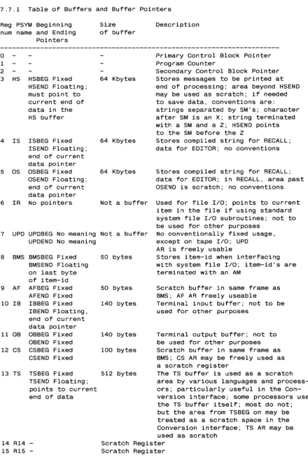
[image:21.618.99.515.496.688.2]3.4 Registers
DEFINITION: There are two types of registers ADDRESS REGISTERS
(AR's) and STORAGE REGISTERS (SR's). These registers are used to
store byte addresses ONLY. They cannot be used to store numbers or
other data.
An AR or SR contains a frame number (FID) and a displacement, which
results in a pointer or reference to a specific byte in a specific
frame. At the assembly instruction level, data can be addressed only
via an address register. A storage register, as its name implies, is
used to save and restore the byte address of an AR. "Address
register" is often abbreviated simply "register."
The terminology "(byte) address of §:. register" will be used to mean "the address of the byte that the reqister is referencing.·" This
should not be confused with the actual physical location of the
register itself, which is largely a matter of indifference, since at
the assembly level data references have at least one level of
indirection (i.e., data references are made through address
registers) .
3.4.1 Referencing AR's and SR's
An address register may be referenced directly, that is, by its
register number (O-X'F'). In this case i t is the contents, or byte
address, of the register that is being referenced. When an indirect
reference is made to the data pointed at by the register, several
methods apply and these are described later under the section
"Addressing Modes."
The contents of a storage register are referenced via an AR as a base
address, plus an offset to its location. The data that an SR are
pointing to cannot be directly referenced; the SR must first be moved to an AR for this to be possible.
Following is an example of an instruction that moves the byte address from an SR into an AR. Both the SR and the AR now point to the same byte.
MOV sr1,ar2 sr1 is
defined via ar1 and offset1
ar1 ---1 byte add ress ---1---1
--- ar2 ---Ibyte address 21
(addresses v
Result of MOV
1
3.4.2 Attached and Detached AR's
DEFINITIONS: An ATTACHED AR is an address register whose referenced byte (therefore frame) is both resident in main storage, and whose physical address has been resolved by the firmware and saved in an internal hardware register or memory location for use in processing instructions.
A DETACHED AR is one whose referenced byte (therefore frame) mayor may not be in main storage, and whose associated hardware register or memory location is in an unresolved state.
Only an attached AR can use its referenced data.
When a process begins execution, all its AR's are in a detached state. As a first step, the firmware attaches Registers 0 and 1 by searching the memory map to determine where in main memory the addressed frames are stored. If the referenced frames are not in main memory, a Frame Fault trap is generated to the Monitor.
If the referenced frames are in main memory, execution begins and the other AR's are attached on a demand basis as needed by the instructions. That is, the memory management routine in the firmware is entered as above whenever a detached AR is used to reference data. A specific AR is detached when a storage register is loaded into it. It will not be re-attached until a data reference is made by using i t in an instruction.
A specific AR also detaches during the execution of an incrementing or decrementing instruction that causes its byte address to cross the logical boundary of the current frame. The memory management routine is entered to re-attach i t to the appropriate frame, and if successful, execution of the interrupted instruction continues. Byte string instructions may go through this process repeatedly since strings may be hundreds or thousands of bytes in length.
All AR's are detached when the process deactivates and returns control to the Monitor, either voluntarily or involuntarily.
Attachment and detachment of registers is automatic and transparent to the programmer.
An AR should be loaded in only one way: by moving an SR into it, which automatically detaches it. It is possible, though not recommended, to set up an AR by physically affecting its fields. If this is done, it is vital to force detachment of the AR before affecting its FID or displacement. The "DETZ r" or "DETO r" instruction may be used to detach the AR explicitly.
ASSEMBLER
Copyright 06 JUN 1983
3.4.3 Format of an Address Register
There are sixteen AR's, Registers RO through bytes in length. An AR contains a byte previously.
R15; each AR is eight address as described
1---0---1---1---1---2---1---3---1---4---1---5---1---6---1---7---1 AR 1 see below 1 Displacement 1 Flags 1 Frame Number (FID) 1
Bytes 0 and 1 are used by the firmware in some implementations, such as that for the Honeywell Level 6 WCS. Along with byte 2, these bytes are used to store the main memory address when the register is attached. In other implementations, the main memory address is stored in a hardware register which is inaccessible to the programmer.
Bytes 2 and 3 are the displacement field. Warning - the field contains meaningful data only when the AR detached state, and therefore should not normally directly in any way.
displacement is in the be changed
Byte 4 is a flag field that contains specific bits as follows: Bit 0 is the Unlinked mode
is in unlinked mode;
flag; if set, the register's address if zero, it is in linked mode.
Bit 1 is the Special Attachment flag. If set, and the displacement is zero, the register will be attached to reference the dummy data byte (byte at physical displacement X'B' or 11) in the current frame. If zero, a displacement of 0 causes normalization and attachment to physical byte 511 of the previously linked frame.
The purpose of this bit is to cause the AR to temporarily address physical byte X'B' of the frame when one of the pre-incrementing data movement instructions reaches a frame boundary. It is then pre-incremented to the first data byte in the frame as instruction execution continues.
Bits 2-7 are reserved.
Bytes 5-7 contain the frame number of the register's address.
3.4.4 Format of a Storage Register
3.5 Registers Zero and One
Address Registers Zero and One have hardware defined meanings.
Register Zero addresses a special frame called the PRIMARY CONTROL
BLOCK or PCB (defined next), which is the basis of all data that a particular process can access.
Register One is the process' PROGRAM COUNTER.
3.5.1 The Primary Control Block
DEFINITION: The PRIMARY CONTROL
unique to a particular process,
reference that the process can
themselves, the Subroutine Return other data variables.
BLOCK, or PCB, is a single frame
and is the basis for every data
make. The PCB contains the AR's
Stack, the Accumulator, and various
The FlO of the PCB is determined when the system is initialized. When the Monitor decides to turn control over to a particular process, its
PCB frame number is obtained from the PIB, and the virtual memory
table is searched for that FlO. If that frame is not in main memory,
the process cannot be activated; the Monitor continues on to other
tasks.
If the frame is resident, Register Zero is attached to byte zero
(unlinked format) of the frame, and this main memory address is saved
in a hardware memory register (inaccessible to the programmer). The
hardware register is then used to reference all other PCB elements,
including the other address registers when they are detached.
Register One is attached first, and the other registers are attached
as needed by the program.
Note that although Address Register Zero is stored in the process'
PCB, i t is not actually used at all, since its displacement field is always assumed to be zero and the FlO is supplied by the Monitor.
The format of the PCB is described later in the chapter SYSTEM
CONVENTIONS.
3.6 Register One
Address Register One has two distinct formats, depending on whether
the process is active or inactive. In the inactive state, Register
One is a true program counter in the sense that i t addresses the
location (less one byte) of the next instruction that the process will execute when i t is reactivated.
In the active state, i t is set attached to byte zero of the program
frame that the process is currently executing. The real program
counter, which actually addresses the next instruction that the
process will execute, is stored in a special hardware register and is inaccessible to the programmer.
The purpose of this peculiarity is that since Register One always
addresses byte zero of the current program frame, data in that frame
ASSEMBLER
Copyright 06 JUN 1983
may be referenced relatively using Register One as ~ base (see the
section on Addressing Modes below). This is the mechanism used to
address literal text and other data in the program frame.
3.7 Registers Two through Fifteen
Registers Two through
thus are general
conventions assign
locations.
Fifteen have no hardware defined meanings, and
purpose registers. But the system software
Registers Two through Thirteen to specific
Register Two points to another control block, called the Secondary
Control Block or SCB whose frame number is fixed as the PCB FID plus
one. This block contains numerous additional elements that have both
system-defined and variable uses.
The format of the SCB and the conventions regarding Registers Three
3.8 Addressing Modes
The system has four modes of addressing data using the address
registers. DEFINITIONS:
i.
Immediate addressing - The datum is in the instruction itself(literal), and can be only one byte in length. For example,
MCC C'A' ,R4 where the constant character "A" is stored within the instruction.
Immediate mode operands are either a single byte to be moved, a
masking field for logical operations or a byte used as a parameter in a variety of instructions.
2. Direct addressing - Reference is to the AR itself; for example,
MOV R14,R15 where R14 is moved to replace the contents of R15, so that the two registers are then identical.
3. Indirect Addressing - Reference is to the byte or byte string
addressed indirectly by the AR. There are three sub-modes in this
section:
a. Indirect byte: The addressed byte is located indirectly by
using the byte address of the register.
b. Indirect byte pre-incremented: The addressed byte is located
indirectly by first adding one to the byte address of the
register. The register remains altered.
c. Indirect string pre-incremented: The register's byte address
is successively incremented by one to generate the locations
of a string of bytes. The length of the string is dependent
on the exact instruction, which may specify one of several
terminating conditions. The register is left addressing the
last byte in the string.
4. Relative addressing - The field (variable length, see below) is
addressed via a BASE register and an OFFSET (fixed in the
instruction) to get the resultant address. That is, a function of
the offset is added to the byte address of the AR to get the
effective address. The function used is dependent on the actual
field being addressed and is described later. Only forward
addressing is allowed, and going beyond the boundary of the frame causes a CROSSING FRAME LIMIT abort condition.
ASSEMBLER
Copyright 06 JUN 1983
3.9 Symbol Types
All symbols or variable names at the assembly level have an associated
symbol
type code.
This code indicates the addressing mode
of the
variable.
Symbols may
be predefined and stored
in a
file called PSYM.
Local
symbols which are defined within a program are stored in a file called
TSYM for the duration of the assembly.
The table below describes the PSYM or TSYM symbol type codes.
Symbol Type
Description
Addressing
Unit of
Max
displace-code
and length
Mode
Offset
ment from AR
---B
A single Bit
Relative
Bits
32 bytes=256
...
C
A character- 1 byte
Relative
Bytes
256 bytes
D
Double Tally- 4 bytes Relative
Words
512 bytes
F
F-type Tally- 6 bytes Relative
Words
512 bytes
«
H
Hal f Tally- 1 byte
Relative
Bytes
256 bytes
L
Local label
Relative
Bytes
256 bytes
•
M
Mode identifier
(External label)
N
Literal
Immediate
R
Address Register
Direct/Indirect
S
Storage Register-
Relative
Words
512 bytes
6 bytes
T
Tally- 2 bytes
Relative
Words
512 bytes
Table of Symbol Type Codes
• Local labels are subject to this limitation only in the SRA
instruction, not when used as targets of a branch, in which case
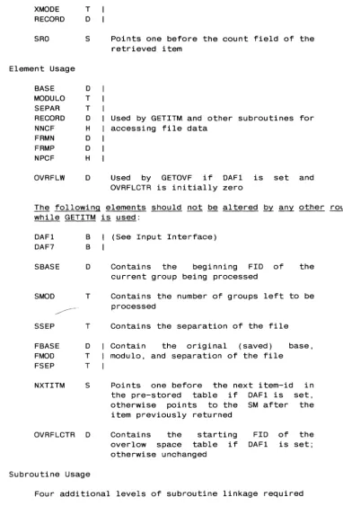
[image:28.617.149.555.242.430.2]3.9.1 Computation of Location from Offsets
Symbols referenced in a Relative addressing mode are addressed via a
base register and an. offset displacement. The resultant address may
be offset up to the limit as mentioned in the table above, though i t
may not cross the boundary of the frame that the register is
addressing.
Offsets are fixed in the instruction and are in the range 0-255. The
offset value is derived from the symbol's definition in the symbol
file.
The column "Unit of Offset" indicates the function used to convert the offset to the effective address.
For example, if the symbol being addressed is a BIT, the offset is
also in bits, so that an offset of 15 would address the 7th bit in byte 1 displaced from the address of the AR. If the symbol is of type
D, the same offset would address bytes 30 through 33 displaced from
the address of the AR. Graphically,
Address Register points to byte
v
bits-1012345671012345671012345671 ... 1012345671012345671012345671012345671
byte-I 0 1 1 1 2 1 1 30 1 31 1 32 1 33 1
Fields addressed
>
using same Offset>
of 15 (X'F')
>
ASSEMBLER
Bit Tally at bytes 30, 31
Double tally at bytes 30-33
Copyright 06 JUN 1983
3.10 Description of Symbol Table Elements
Address registers (type R) and storage registers (type S) have already
been described. Local labels (type L) and mode identifiers (type M)
are described in the next chapter. The other symbol types are
described below.
3.10.1 Bits
Any bit within the first 32 bytes offset from the byte address of a
register may be addressed relatively. Bit instructions may set, zero
or test a bit.
3.10.2 Characters
A type C element is a single character or byte addressed relatively
using a base register and an offset. The difference between
addressing a byte as a type C and addressing i t indirectly is that in the latter case, the register must point to the byte itself; in the
former, it may point up to 255 bytes before i t (but in the same
frame) .
3.10.3 Counters or Tallies
Counters or TALLIES contain a signed (two's complement form) integer
which may be used in arithmetic operations. There are four types of counters:
tallies (Type T), 2 bytes; double
F-type tallies (Type F), 6 bytes.
half tallies (Type H), 1 byte;
tallies (Type D), 4 bytes; and
The half tallies are rarely used, since they can only store numbers
in the range -128 through +127.
The tallies are used most frequently, since their range is -32,768
through +32,767.
Double tallies have a range of
typically used to store FlO's (base to count items in a file.
-2**31 through +2**31-1 and are
FlO of a file, for instance), and
F-type tallies are used
48-bit precision of the -2**47 through +2**47-1.
for any arithmetic that requires the full
CHAPTER 4
THE ASSEMBLER
4.1 Introduction
The ULTIMATE
assembly language is a
language which
has many instructions
base management.
powerful
high-level assembly
designed specifically for data
4.1.1 The Assembler and Related Processors
The ULTIMATE Assembler translates source statements into ULTIMATE CPU
machine language equivalents.
The source program,
or "mode" is an
item in any disc file.
The program is assembled in place;
that is,
at the conclusion of the assembly process, the item contains both the
original source statements, as well as the generated object code.
The
same item can then be used to generate a formatted listing (using the
MLIST verb) or can be loaded for execution
(using the MLOAD
verb).
The diagram below illustrates the interaction of the various assembly
functions:
EDit a program
-->
ASsemble the program
1
--->
MLIST to get listing
v
assembly errors
1-->
MLOAD to load object code
1-->
MVERIFY to verify loaded code
1-->
CROSS-INDEX to generate
or changes to source
concordance listings
The assembler
is table driven and performs two passes over the source
code.
During the first pass, all instructions that have undefined and
forward references are flagged as requiring re-assembly.
Local labels
are stored in the temporary symbol
file during this pass, along with
literal definitions that need to be created.
At the end of pass one, the literals are generated and added to the
end of the current object code.
Pass two
then re-assembles all the
flagged instructions and concludes the assembly.
The assembly
instructions generate object code
length, from one to six bytes.
Each instruction
three explicitly defined operands.
In addition,
implicitly reference Address
Register
15 or the
section describing each instruction mentions such
detail.
that is variable in
may
have zero to
some instructions
accumulator.
The
"side effects" in
ASSEMBLER
Copyright 06 JUN 1983
4.2 Editing a Source Item
Each line in the source item contains a single assembly statement.
The general format of a source line is:
{Label} opcode operand{,operand, ... } {comments}
The source item is entered via the system EDITOR, and is free form.
Several commands are available in the EDITOR
to display the source
(and object, if any) in conventional assembly listing format,
which
makes editing and modification much easier:
Command
AS
M S
Q/locni
... Description . . . .
A switch which causes the assembly listing format to
be turned ON or OFF.
Each entry of "AS" toggles this
switch. It may also be called into effect by using the
"A" option when
calling the EDITOR.
When using this
option, the format of the source as displayed should
not be confused with the format used when inserting or
changing lines, which is free form (described next).
A switch which causes the display of assembler Macro
expansions to be turned ON of OFF. It is initially off.
A switch which causes the display of object code to be
turned ON of OFF. It is intially on.
Is used to locate the line with object code location
"locn". This command is different from the L/stringl
in that it searches only in the object code for the
location matching that specified.
When a program is assembled, macro expansions and the generated object
code are stored along with
the source statement using
system
delimiters to separate the various components.
While editing an
already assembled program, any data beyond the source statement may be
completely ignored, since the assembler examines only the source data
on each line as it performs the assembly;
existing object code, etc.
are discarded.
4.2.1 Format of a Source Item
1.
The assembler expects the assembler directive FRAME to be on
the
first line of the source item.
2.
The
next five
lines (lines 2-6)
are conventionally used for
comments concerning the program type, revision level, author, etc.
The assembler will automatically write the assembly date (as a
comment) on line 3, unless this line is initially a
non-comment
4.2.2 Examples of EDIT Display
With the AS function off:
013 SAVEIT MCC R4.R5 MOVE THE TERMINATOR\0056 6450
014 MCC R4.R16 SAVE IT ALSO]*ERR: REF: UDEF. REF:UDEF
015
B OK] B: OK\0058 lE45
(Note the spaces in the first column of lines 14 and 15.)
With the AS function ON, S function OFF and M function OFF:
013 0056 6450
014
SAVEIT
ERR: REF:UDEF. REF: UDEF
MCC
R4.R5
MCC
R4.R16
015 0058 lE45
B
OK
MOVE THE TERMINATOR
SAVE IT ALSO
With the AS function ON, S function ON, M function OFF:
013 SAVEIT
014
015
MCC
R4.R5
MCC
R4.R16
B
OK
MOVE THE TERMINATOR
SAVE IT ALSO
(Note that the error message on line 14 was also suppressed.)
With the AS function ON. S function ON. M function ON:
013 0056 6450
014
SAVEIT
MCC
R4.R5
MCC
R4.R16
ERR: REF:UDEF. REF: UDEF
015
0058 lE45
ASSEMBLER
B
OK
+B:
OK
Copyright 06 JUN 1983
THE ULTIMATE CORP.
MOVE THE TERMINATOR
SAVE IT ALSO
4.2.3 Labels
The optional label, if it exists, must start· in column one, and
must
begin with an alphanumeric character.
It may
be up to 50 characters
in length, though for listing formatting purposes, only ten spaces are
reserved.
Labels should not contain the following characters:
*,1,+.The label is separated from the opcode mnemonic by a space.
If there
is no label, at least one space must precede the opcode.
If the label
starts with an asterisk
(*),the entire source line will be considered
a comment and will be ignored by the assember.
Labels are locally defined symbols
that are used to address locations
in the program or other symbolic types.
They must be used as the
target of all instructions that execute a conditional or unconditional
branch.
Examples of valid labels are:
LOOP
TEST.TOTAL
RESTART-X
RESTARTl01
4.2.4 Opcodes
The opcode is separated from the label and the operand(s) by
at least
one space.
The legal opcodes are defined
in the OSYM file, which is
described later.
An opcode may
be a machine
instruction,
a
macro definition
that
expands to a set of machine instructions, or an assembler directive.
Examples of opcode mnemonics are:
MOV
BCHE
EQU
A specific opcode mnemonic does not determine
since the latter is dependent on the operands
The MOV opcode, for example, allows a
number
and each combination produces a
different
instructions.
the actual instruction,
used with
the opcode.
4.2.5 Operands
The operands for the instruction follow the opcode and are separated
from i t by at least one space.
An operand may be one of the following:
1. A literal in one of the following forms:
a. A single
C' ABCD' . adjacent represent
printable character or a text string: C'x' or
If a single~quote is needed as a literal, two
single quotes must be used; for example, to
the string JOHN'S, the operand would be C'JOHN"S'. b. A decimal integer: n' , for example, 12 or -1234.
c. A hexadecimal constant: X'xxxx' ; for example, X'FE' or
X'8100FF'. If an odd number of hex characters are used, a
leading zero is assumed to fill the left most nybble.
2. A symbol as predefined in the PSYM file, or as defined in the
label field of the source program.
3. The "current location" function, * This function is used to
specify the current location or address being assembled. The
assembler maintains a byte location counter which is the the
location of the first byte of the current instruction being
assembled. This location advances as instructions are assembled
and can be altered only by the assembler directive ORG (origin).
Specific forms of this function are:
*
*n
Returns the current location in bytes.
Returns the current location in units of "n" bits. For example, *1 would return the location in bits, *8 is identical to *, and *16 returns the location in words.
4. A combination of literals or the * function combined with a + or a Symbols cannot be used in such combinations.
Multiple operands are separated from each other by a comma; no spaces are allowed within this field except in quoted character literals.
ASSEMBLER
Copyright 06 JUN 1983
Examples of operand fields are:
MOV 100 ,COUNTER
MOV X'64' ,COUNTER
LABEL EQU *-1
BCHE R15,C'A' ,OK.TO.GO
4.2.6 Comments
The optional comment field follows the last operand and is
unrestricted in length, though again the listing processor will
4.3 Assembled Object Code
There is no link-editing mechanism
into a specific frame, and must
limitations in mind:
in the assembler. be written with
A program loads
the following
1. The assembled object code must be less than or equal to 512 bytes in length (one frame).
2. The frame into which the program is to load must be explicitly
specified with the FRAME assembler directive.
3. All interframe linkages must be explicitly established and coded.
Branches outside the current frame use different opcodes than
local branches, though the mnemonic for subroutine calls is
identical whether the destination is local or in another frame.
4. The first executable location in ~ frame is the byte at location
one (unlinked format), not zero. The FRAME assembler directive
also sets the assembler's location counter to one for this reason.
Byte zero can be used for storage (remember Address Register One
points there); to do so, the ORG assembler directive must be used to reset the location to zero and store a byte there.
4.3.1 The Mode-id
DEFINITION: A MODE-ID is a sixteen-bit field (therefore a tally can
store it) which has a four-bit entry point and a twelve-bit FlO. It
is an encoded address to which execution control can be transferred
via the ENT (external branch) or BSL (external subroutine call)
instructions. The actual location addressed is twice the entry point
number plus one.
Up to sixteen entries to a frame of object code are allowed;
typically there are unconditional branch (B) instructions forming an
entry table (called the Dbranch tableD) at the beginning of each
program. This allows the program body to be changed and reassembled,
without affecting the entry pOints - an important concept.
strictly speaking, for safety, there should be sixteen branches even
if not all of them are used; in practice, only as many branches as
are being used need be present.
A mode-id may be defined by the DEFM assembler directive, which
defines a symbol, or by the MTLY directive, which defines a symbol and reserves storage in the program for the mode-id. For example,
EXT.SUB DEFM 4,500
defines the symbol EXT.SUB as a mode-id whose value is entry point
four in frame 500, and is therefore byte nine in that frame.
ASSEMBLER
Copyright 06 JUN 1983
Following are further examples of the relationship between the mode-id
and the value of the resultant address:
Mode-id
Entry point
Addressed Location
{FlO. location}
01FF
0
511.1
11FF
1
511.3
21FF
2
511. 5
F1FF
F (15)
511 .1E
A typical sequence at the beginning of an assembly program is shown
below:
Line Object code
Label
Opcode Operand(s)
Comments
001
0001 7FFF01FF
FRAME 511
Establish frame# for MLOAO
002
* Note: lines 2-6 are comments
003
*21 MAY 1983
004
*
005
* Note: the sequence of unconditional branch
006
* instructions (B) , below, must be the first
007
* ones that generate object code.
008 0001 1E34
B
START
Entry point a - location
009
0003' 1F22
B
CaNT
Entry point 1 - location
010 0005 1E88
B
SUBR1
Entry point 2 - location
011