Uninterruptible Po-wer Supply
Application Guidelines
fortheARIX
Systern,90
ARIX Corporation
821
Fox
Lane
San Jose, CA 95131
The document contains proprietary infonnation issued with the corresponding system product under the tenns of a written agreement.
Copyright 1989, ARIX Corporation. All rights reserved.
No pan of this publication may be reproduced without the express written permission of ARIX Corporation. The information in the publication is subject to change without notice, and is considered to be current at the time of preparation. This information is provided as a convenience to the user, and by acceptance thereof, the user specifically releases ARIX Corporation from any
Table of Contents
Chapter 1 Introduction
UPS - General Infonnation ... 1-1 Chapter 2 UPS Environmental and Electrical Guidelines
Chapter
3
UPS InterfaceChapter 4 UPS Installation Comments Chapter
5
Notes., Cautions and WarningsList of Figures
Chapter
3
UPS InterfaceFigure 3-1 UPS to System90 Electrical Interface ... 3-2 Figure 3-2 System90 UPS OFF Signal Interface ... 3-2 Figure 3-3 UPS Alcirms Driving System90 Alanns separately ... 3-3
Figure 3-4 UPS LOW .BA TTERY Alann Driving
both System Alarms ... 0 3-4
List of Tables
Chapter 2 UPS Environmental and Electrical Guidelines
Table 2-1 UPS Sizing ... 0 • • 0 • • • 0 • • • • • • • 0 • • 0 0 . 2-1
Table 2-2 Environmental Guidelines for the UPS ... 2-3 Table 2-3 Battery and Backup Characteristics for th~ UPS ... 2-3 Table 2-4 Electrical Specifications for the UPS ... 2-4 Chapter 3 UPS Interface
k: ::: ::::: :: .:: :--::::::::: :::::--:_._ ... _._-_: .. :
...
:",u.. :liiiiiiiiiiiiti:··uu:u: ...
f{:.
This document describes guidelines for a UPS (unintenuptible power source) for use with the various members of the ARIX S ystem90 family. This document is intended to assist ARIX customers in their selection and integration of a UPS product for use with the ARIX System90 family.
The primary function of a UPS is to provide power in the event of a utility power failure, brownout or severe voltage fluctuation. Additionally, many. UPS products provide voltage regulation, transient suppression and power line futering. ARIX recommends that a unit with these features be chosen because it can substantially improve the long tenn reliability and availability of the computer system.
You may use either a stand-by or on-line type of UPS, but it must meet all of the guidelines listed in the following chapters.
• Section 2 contains UPS environmental and electrical guidelines.
• Section 3 contains guidelines for and describes the UPS signal interface.
• Section 4 contains guidelines for UPS installation.
• Section 5 contains notes, cautions and warnings about UPS installations.
UPS - Generallnfonnation
A UPS provides protection against failed power, out of range power (too high or too low), electrical noise, and voltage surges. A UPS connects between the utility company's electrical power source and the computer system's power supplies, thus protecting the system elec~calload. A UPS typically includes batteries, battery charger, a voltage inverter, and a transient suppressor and filter network. Some UPS models combine the features of a power conditioner with those of a UPS by including dynamic power conditioning, which regulates the output voltage and isolates the load from the ac input line by means of an isolation transformer.
During notmal operation when utility power is available, the battery charger keeps 'the batteries fully charged. When the UPS detects the electrical utility's ac output
voltage is outside the nominal range, the UPS draws energy from its batteries to provide ac power to the load. The switch-over occurs rapidly and the protected system experiences no noticeable loss of ac power. Even with a sudden blackout, the time from "detect" to "switch" must be less than two milliseconds.
When the utility line voltage returns to a usable level, a line voltage monitor in th~
UPS stans the battery charger and recharges the batteries. Many UPS systems Ie' you install extra batteries to extend the system running time beyond the ten-minute minimum.
The duration of backup battery power depends on the rating of the UPS, the number of batteries installed, the magnitude of the load, and whether the batteries are fully charged.
To increase the reliability of your computer system, the UPS should also protect the system from surges anc;i noise by filtering and providing surge suppression for both common mode and transverse mode. This feature is not required, but is highly recommended.
UPS models with dynamic power conditioning usually switch to the inverter at variances of +20% or -20% from nominal. Such models also provide the additional
protectio~ of an output isolation transfonner that eliminates direct electrical
connection between the· load and the ac input line and greatly improves common-mode noise attenuation.
CAUTION:
~~---~----
~
Electrical Guidelines
Use the following infonnation to ensure that a UPS used with the ARIX System90 family meets the recommended guidelines.
Unless othenvise noted, the following guidelines apply equally to the all models of the ARIX System90.
CAUTION
The ARIX System90 Model
2S
may be configured to
operate at a nominal line voltage of either 110 V AC or a
220 V AC.
The local utility line power determines the
required input and output frequencies. Always check that
the
UPS
and the Model 2S are configured properly for the
applicable ac' output.
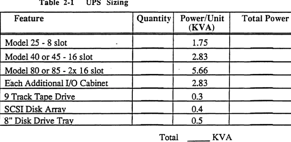
Following is a table which allows you to calculate the approximate power required from a UPS to suppon a System90 configuration. Multiply the quantity of each item by the PowerlUnit to get Total Power. Add the Total Power numbers together to get the minimum required KV A rating of the UPS.
Table 2·1
UPS Sizing
Feature
Quantity Power/Unit
Total Power
(KVA)
Model 25 - 8 slot
-
1.75
Model 40 or 45 - 16 slot
2.83
Model 80 or 85 - 2x 16 slot
5.66
Each Additional I/O Cabinet
2.83
9 Track Tape Drive
0.3
SCSI Disk Arrav
0.4
"8" Disk Drive Trav
0.5
[image:6.615.113.584.455.685.2]The actual time that the UPS can suppon the system on batteries is dependent u~\
the load on the UPS and the capacity of the batteries. With the UPS properly s i V for the load (correct KV A rating), the suppon rime can be extended with the
addition of more batteries to the UPS.
The actual time required to complete an orderly system shutdown will vary with the system configuration and workload. ARIX recommends that you test your
configuration, and verify that sufficient battery power is available to complete a system shutdown.
The guidelines noted here for the UPS are, in many instances, identical to the specifications for the ARIX computer system. Therefore, if your ARIX computer is being operated outside of its specifications, the UPS will likely also be operating outside of these guidelines. This variance from the specification should be taken into acc9unt when purchasing, installing, and operating the UPS.
In addition to the power or KV A rating of the UPS there are several other imponant requirements. The UPS unit should carry UL approval or whatever
safety/regulatory approvals are required where the unit is to be installed.
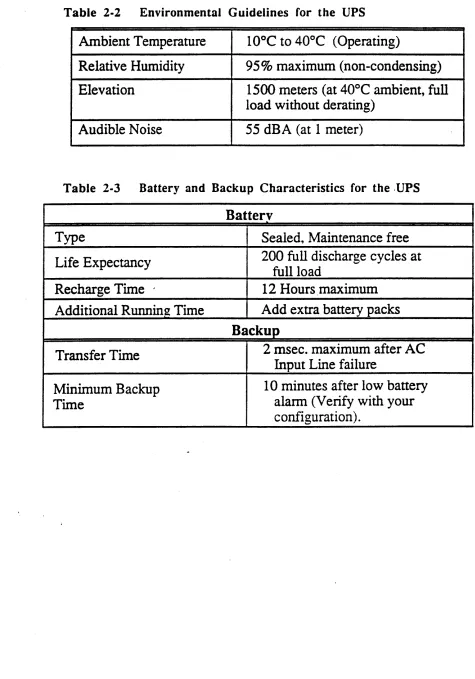
Table 2-2 details the environmental requirements for the UPS to be compatible with the System90 environmental limitations. These items are meant as guidelines only
and may change slightly according to the individual installation.
Table 2-3 details battery and backup characteristics.
Table 2·2
Environmental Guidelines for the UPS
Ambient Temperature
10°C to 40°C (Operating)
Relative Humidity
95% maximum (non-condensing)
Elevation
1500 meters (at 40°C ambient, full
load without derating)
Audible Noise
55 dBA (at 1 meter)
Table 2·3
Battery and Backup Characteristics for the .UPS
Batterv
Type
Sealed, Maintenance free
Life Expectancy
200 full discharge cycles at
full load
Recharge Time .
12 Hours ,maximum
Additional RunninJZ Time
Add extra battery packs
Backup
Transfer Time
2 msec. maximum after AC
Input Line failure
Minimum Backup
10 minutes after low battery
Time
alann (Verify with your
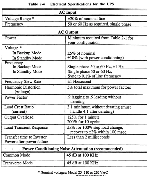
[image:8.612.108.583.69.748.2]Table 2-4
Electrical Specifications for the UPS
AC Input
Voltage Range
*
±20% of nominal line
Frequency
50 or 60 Hz as required, single phase
AC Output
Power
Minimum required from Table 2-1 for
your configuration
Voltage
*
In
Backup Mode
±5% of nominal
In
Standby Mode
+10% (with power conditioning)
Frequency
In
Backup Mode
Single phase 50 or (>0 Hz,
+
1Hz _
In
Standby Mode
Single phase 50 or 60 Hz,
Sync to 0.1 % of line frequency
Frequellcy Slew Rate
+1 Hz/second
Hannonic Distortion
5% total maximum for power factors
(voltage)
Power Factor
.9 lagging to .9 leading without
derating
Load Crest Ratio
3:1 minimum without derating (must
(current)
handle 4: 1 after derating)
Output Overload
125% for 1 minute
200% for 10 cycles
Load Transient Response
+8% for 100% step load change,
-
recover to +2% within 100 msec.
Transfer time to Inverter
Less than 2 milliseconds
Power after power failure
Power Conditioning Noise Attenuation (recommended)
Common Mode
Transverse Mode
45 dB at 100 KHz
45 dB at 100 KHz
*
Nominal voltages: Model 25 110 or 220 V AC (factory configured) Model 40 or 45 220 V AC ONLY Model 80 or 85 220 V AC ONLYI
I
[image:9.617.92.598.78.684.2]\-._._----_ .... _._ ... =:: ...
:.q.
ll__ _ _ _ _
." ... _."'., ... ,.. ...
".YoYoy"""""".,...," .... w, ...Yo_,.-..,.,."""'"""---t:J:ES:::l11t,e,rfrcc.-e~
... _
..
;:1:
All models in the System90 family suppon the same alann interface to a UPS. The rear panel of each system has a male DB-9 type connector labeled "UPS". This is the UPS interface connector. The interface is designed to accommodate signals commonly available from UPS products. Two alann signals are supplied by the UPS. They are: AC FAll. and LOWBATIERY.
AC FAIL indicates that the utility power has failed artd the system is running on battery power from the UPS. This signal should appear immediately when utility line power fails.
LOW BATTERY indicates that the UPS battery power reserves are low and that the system must complete its shutdown procedures. The LOW BA TIER Y signal must become active when the UPS has approximately 10 minutes of power remaining. The exact length of time required to shutdown a system is dependent on its size and configuration. Less than 10 minutes warning may be acceptable depending on your system. In order for the system to recognize the LOW BATTERY signal as valid the AC FAIL signal must also be true.
The S ystem90 supplies a UPS OFF signal for those UPS units' that can accept a tum off command to save battery power. When the system has completed its shutdown and powers down, it sends the UPS OFF signal to deactivate the UPS. Use of this signal is completely optional; some UPS units do not suppon iL
Due to the major effect an alann from the UPS causes, the cable carrying the alann signal to the processor cabinet
must
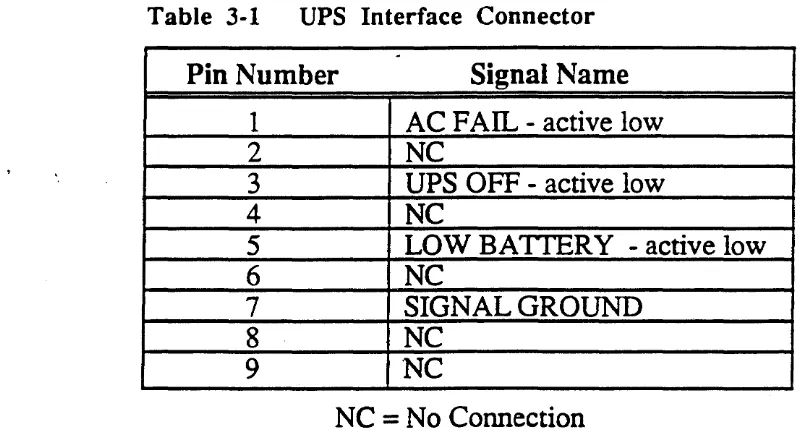
be shielded. This will prevent spurious electrical noise from inducing a false alarm.Table 3-1 details the pin-out of the System90 UPS interface connector.
Table 3-1
UPS Interface Connector
~
Pin Number
Signal Name
1
AC FAIL - active low
2
NC
3
UPS OFF - active low
4
NC
5
LOW BATTERY - active low
6
NC
7
SIGNAL GROUND
8
NC
9
'NC
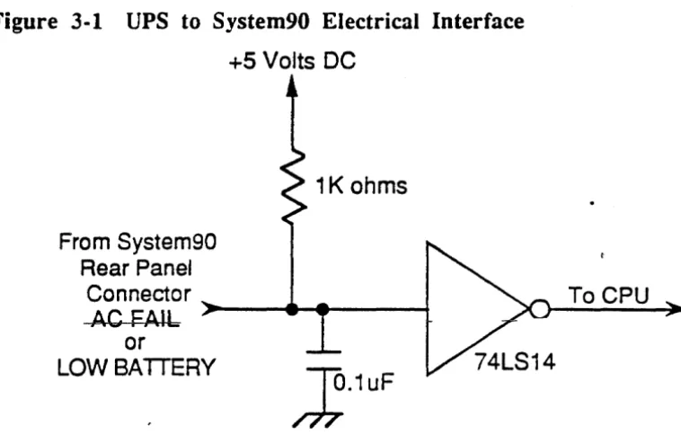
[image:10.617.99.500.495.714.2]The two alarm signals from the UPS are connected to the input of a 74LS 14 I
inverter on the System90. Each signal line has a 1 K ohm pullup resistor and a u~
uF
filter capacitor to ground. All signals are active low (they are true when less than 0.8 VDC). Figure 3-1 illustrates the System90 electrical interface.Figure 3-1 UPS to System90 Electrical Interface
+5 Volts DC
From System90 Rear Panel
Connector
1K ohms
AC FAIL ~---+
or
LOWBAITERY
~.1UF
To CPU
The UPS OFF signal is driven by a 7407 open collector buffer with a 4.7 K ohlli pullup resistor to
+
12 VDC~ This interface is shown in Figure 3-2.Figure 3-2 System90 UPS OFF Signal Interface
+12 Volts DC
4.7K ohms
To
System90Rear Panel ~-~a--~
Connector
UPS OFF
(Open Collector)
From CPU
Usually the system's AC FAIL* (low true) alarm is driven by the UPS's AC FAIL
[image:11.617.191.570.136.378.2] [image:11.617.82.586.426.663.2]UPS
ACFAIL
Signal
alarms (AC FAIL* and LOW BATrERY*) are driven by the UPS's LOW BATTERY signal (Figure 3-4).
Whichever interface connection you have, A C FAIL * must be true when the system's LOW BA TrERY* alann is true.
The LOW BA TfERY alann signal must occur at least ten minutes before the UPS system batteries drain to the point that the UPS shuts itself down. This ensures that the processor has sufficient time to write buffers out to the disk(s) and perfonn any other pre-defmed power fail shutdown tasks. After the processor has completed its shutdown tasks it will turn its own power off.
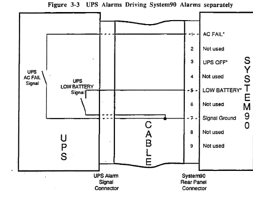
Figure 3-3 illustrates a possible UPS cable connection with an ARIX System90. The UPS's LOW BATIERY and AC FAn... signals are shown separately driving the two system alarms using relays (opto-isolator transistors could be used as well).
Figure 3-3 UPS Alarms Driving System90 Alarms separately
-_
..
-
-1- - ACFAIL-2 Not used
3 UPSOFP
S
Y
4 Not used
S
UPS
LOW BATTERY
Signal
I
-s ..
LOW BATTERY·T
U
P
S
-
--.. ~....
-UPS Alarm Signal Connector ..l.
-C
A
B
L
E~
6 Not used
-7- - Signal Ground
8 Not used
9 Not used
System90 Rear Panel
Connector
Figure 3-4 illustrates a second possible UPS cable connection with an ARIX System90. The UPS's LOW BATTERY signal is shown driving both system
alarms using either an opta-isolator transistor or a relay.
E
M
9
[image:12.615.82.586.241.633.2]Figure 3-4 UPS LOW BATTERY Alarm Driving
both
System Alarms
UPS
-
----LOWBAITERY
Signal
...
, ' "-
--
--1-2
3
C
A
4AC
FAIL-Not used
UPS OFF-
S
y
Not used
S
B
+- LOW BATTERY·T
L
opto-isolator ....
-transistor V1l
- . " " ,
U
p
S
[image:13.623.132.600.75.715.2].1 .
...
"
-
--UPS Alarm Signal Connector~
-
----F; Nnt IIC:Cri -7- - Signal Ground
8 Not used
9 Not used
A UPS installation typically requires cenain clearance minimums for proper accessibility and ventilation. Also, install the UPS away from excessive dust and chemical fumes. Check the UPS manufacturer's manuals for warranty or other paniculars regarding nonnal operation and proper application of uninterruptible power supplies.
Common safety requirements include the following:
• An A C input line circuit breaker
• A DC battery circuit breaker or fuse
• An AC output line circuit breaker
A UPS installation should meet any local safety requirements.
A~---,.,."-
... ,.,,.::::::::::::: ::: .. ___
n ... _ ...~;"
. . . - - . - - . -• • •--.----;---.-.-1:
1
~
: ::: ...
' m . . "'l¥l1~tes,-"ea.utl,lJm'"'
..
~~~
and Warnings
This section contains notes, cautions, and warnings that apply to all UPS
installations. Always follow the manufacturer's recommended safety precautions for any electrical equipmenL
Whenever installing electrical equipment such as an ARIX computer system or an uninterruptible power supply (UPS), be sure that the UPS voltage and power rating match the available line voltage and load requirements. Also be sure that the UPS output voltage matches the computer system requirements.
CAUTION
Turn OFF the
AC
input circuit breaker and all battery
circuit breakers and unplug the
AC
input cord of the UPS
before changing or making any connections.
Follow the UPS manufacturer's instructions when installing or using a UPS, plugging in battery cables, connecting the AC input to a utility outlet, or connecting the UPS into the system load.
NOTE
In
case of a prolonged power shutdown, such as a regular evening or
weekend power shutdown in the building, always switch the UPS
OFF.
When utility power is shut off, the UPS reacts the same as if a power failure occurred and and begins supplying backup power. Unless it is switched off, the UPS will run until the batteries discharge completely.
CAUTION
Norma! running of a UPS keeps it fully recharged. The maximum recharging period after using the battery-activated invener to supply power to the system can be up to 12 hours. Before storing a UPS~ fully charge the batteries by leaving it plugged in and turned on for at least 12 hours. Avoid pennanent battery damage by storing batteries at room temperature. Freezing or overheating can damage
batteries.
Internal reactions in batteries cause a slow self-discharge even at room temperature. A void high temperatures~ and store batteries at lower temperatures for longer storage life. For fullest capacity and longer life, repeat the recharging process on any batteries stored for over 60 days (or as often as recommended by the
manufacturer).
NOTE
Double check that the battery circuit breakers are turned off before
storing UPS batteries.
Handling and especially shipping batteries requires panicular care. Troubleshooting a UPS is recommended for qualified technicians only.
WARNING
Batteries have a high short-circuit capacity.
Mistakes
Ir •.
connecting or disconnecting may cause an arc or weld that
jcould result in severe burns.
Always use eye protection
I
when \vorkin \vith batteries.