MINUTEMAN
COMPUTER
USERS
GROUP
D17B COMPUTER
MINUTEMAN COMPUTER
USERS GROUP
017B COMPUTER
PROGRAMMING MANUAL
SUPPLEMENT
Edited By
ChaPZes H. Beck
Professor' and Director
SYSTEMS LABORATORY
Department of Electrical Engineering School of Engineering
TULANE UNIVERSITY
REPORT MCUG-2-72
*
0178 Operational Procedures,
*
0178 Programming Techniques
*
0178 Programming Modules
*
017B Subroutines
*
Corrections to the 0178 Programming Manual
PREFACE
This publication of the MINUTE~ COMPUTER USERS GROUP serves as a supplement to the DZ?B COMPUTER PROGRAMMING ~NUAL, Report MCUG-4-71. It contains many of the significant software develop-ments completed in the Systems Laboratory at Tulane University. This supplement includes D17B operational procedures, programming techniques, the programming module set, and a description of some of the available D17B subroutines. A few additions and corrections to the DZ?B COMPUTER PROGRAMMING MANUAL are also included.
Arrangement of the material is specified by the table of con-tents on the following page which lists the first page number for each section. Lists of tables and figures are also included.
Additions and corrections will be distributed to MCUG members for the purpose of updating this publication as they are received. Please send correspondence to the Chairman of the MCUG at the following address.
Dr. Charles H. Beck
Professor of Electrical Engineering Tulane University
New Orleans, Louisiana 70118
TABLE OF CONTENTS
PREFACE
CHAPTER 1 - D17B OPERATIONAL PROCEDURES • • • • • • • • • • • •
Page
11
1
1.1 Instructions for the Operator Control Panel • 1 1.2 Sequence of Operations for the Load Mode •• •• 3 1.3 Sequence of Operations for the Compute Mode' • • •• 5 1.4 Minuteman D17B Computer Checkout Procedure •• 6
CHAPTER 2 - D17B PROGRAMMING TECHNIQUES
• • • • • •
0 0 • 0 • 0 0 72.1 Minimal Delay Coding (MDC) 0 0 0 0 0 0 0 0 0 0 • 0 0 7
2.2 Optimum Storage Programming 0 0 0 0 0 0 0 o . 9
2.3 Scaling of Constants • 0 • 0 0 0 0 0 0 0 o . 9
2.4 Coding Examples 0 0 0 • • 0 • • 0 • 0 • 0 0 0 0 0 • 0 11
2.5 Flag Store Codes • 0 • • • • • 0 0 0 0 0 • 0 0 0 11
2.6 Exceptions for Instruction Codes 0 0 0 0 11
2.7 Subroutine Linkage 0 • • 0 0 0 0 0 0 0 0 0 • 0 0 16
2.8 Address Modification • 0 0 0 0 0 0 0 0 0 0 0 0 0 0 0 19
CHAPTER 3 - D17B PROGRAMMING MODULES
0 0 0 0 0 0 0 0 213.1 Arithmetic Operations • • • 0 •
3.2 Control Operations 0 0 •
3.3 Input/Output Operations 0 • • • 0 0
CHAPTER 4 - D17B SUBROUTINES • • • • • •
0 • •.
.
.
. . . .
• 0 0
.
.
. . .
. .
o •
23 26 28 30 4.1 Exhaustive D17B Diagnostic Program o . 0 0 • 0 30
4.2 8-bit VOA Character Output 0 0 0 0 • 0 0 0 0 0 0 0 0 36
4.3 Octal Contents Output 0 • 0 0 • 0 • 0 0 0 0 0 • 0 o . 36
4.4 Memory Dump Routine 0 0 0 0 0 • 0 • • 0 0 • 36
4.5 Waveform Generation 0 • 0 • 0 0 • • 0 0 0 37
4.6 Linear Interpolation • 0 • • o . 37
4.7 Linear Scaling • 0 • 0 0 • • • 0 • 0 • • 0 0 0 0 37
4.8 Accumulator N-bit Rotation o . 0 • 0 • • 0 0 0 0 o . 37
4.9 Accumulator Bit Reversal •• 0 0 0 • 0 • o . 37
4.10 Logic EXCLUSIVE OR Operation • 0 • 0 0 0 0 • • 0 37
4.11 Binary-to-BCD Conversion 0 0 • • • 0 • • • 0 • 0 37
4.12 BCD-to-Octal Conversion • • • • 0 • • 0 • • • 0 37
4.13 Von Neumann Division •• 0 • 0 • • 0 • • • • • 0 37
4.14 Numerical Integration· • • • •• 38
4.15 Factorials • • • • •• 0 0 • • • • • • • • • 38
4.16 Reciprocal of a Constant • • • • • • • • •• 38 4.17 Sin/Cos Routines • 0 • • • 0 • • 0 • • • • • • 0 • • 38
4.18 Negative Natural Exponential (e-x) •• • 0 0 38
4.19 Natural Logarithm In(x) • • • • • • •• 0 • • • 0 38
4.20 Floating Point Multiply • • • • • • • • • • •• 0 • • 38
4.21 Floating Point ADD/SUB • o . • • 0 0 • • 0 • • • 38
4.22 Statistical Mean and Variance 0 0 • 0 • • 38
4.23 Fast Fourier Transform (FFT) • • • • 0 • • 0 39
4.24 Interactive Arithmetic •• • • o . 39
4.25 Optimization • • • • • • • • • • • • • • o . 39
CHAPTER 5 - CORRECTIONS TO THE D17B PROGRAMMING MANUAL •
• ••
40LIST OF FIGURES
PAGE
Figure 1-1. Sequence of operations for the load mode • • • • • • •• 4 Figure 1-2. Sequence of operations for the compute mode • • • • 5 Figure 4-1. Flowchart for exhaustive D17B diagnostic program
LI ST OF TABLES
Table 2-l. Example of operand address modification •
· ·
• •Table 2-2. Coding examples for unflagged instructions
·
Table 2-3. Coding examples for flagged instructions· · · ·
Table 2-4. Flag store codes. .
•. .
•. . . . · · ·
•· ·
Table 2-5. Exceptions for instruction codes
. .
•· ·
•·
•Table 2-6. Standardized D17B subroutine linkage • •
·
•·
Table 2-7. Typical address modification examples
·
•· ·
•·
•·
• •·
• •·
·
•·
•
·
·
.
·
• •·
• • •·
·
•32
PAGE
8
12 13 14 15 17 19 Table 2-8. Examples of address modification using rapid-address loops 20 Table 3-1. D17B programming modules • • • • • • • • • • • • • • •• 22 Table 4-1. Exhaustive D17B diagnostic program • • • • • • • • • •• 34
1
CHAPTER 1
0178 OPERATIONAL PROCEDURES
1.1 Instructions for the Operator Control Panel .Light Display:
000 000 000 000 000 000 000 000
RUN-HALT:
SINGLE CYCLE: Precede by MASTER RESET or COMPUTE code MASTER RESET:
Set RUN-HALT to HALT
Input Keyboard:
FILL:
Each set of three adjacent lights represents a binary-coded octal digit. The upper row repre-sents the left-half data/instruction word, and the lower row represents the right-half of the 8-digit word. The octal value corresponding to each digit equals
(S4 x 4)
+
(S2 x 2)+
(81 X 1)Each S is 1 or 0 depending on the state of the n
corresponding light (ON or OFF). For example, if S4 and Sl are ON and S2 is OFF, then the octal equivalent will be 4 + 1
=
50RUN starts the computation at the location speci-fied by a transfer instruction (TRA) in the 1-register following either a MASTER RESET or COMPUTE code.
HALT places the computer in the Halt mode.
This will cause a single instruction to be execu-ted whenever it is depressed. RUN-HALT must be in the HALT position.
MASTER RESET initializes the following sequence: (a) Establishes the R V'K'J' mode.
c c
(b) Places the computer in the Prepare to Operate submode.
(c) Achieves. bit counter synchronization.
(d) Places a TRA to channel 00, sector 000 in the I-register.
(e) Resets the Phase Register.
(f) Clears the discrete output matrix.
Keys are numbered 0 through 7 for the octal datal instruction inputs. When a key is depressed, the respective information is loaded into the least significant digit of the L-register, and the previous contents will be shifted one digit to the left.
LOCATION: This code causes the contents in the L-register to be transferred to the I-register which then operates as.a location counter. The low order four octal digits represent the address.
ENTER: This code causes the contents in the L-register to enter the D17B memory location specified by the location counter in the I-register.
2
VERIFY: This code causes the computer to compare the information following the verify code with the information previously stored in corresponding locations in the computer memory. The Sb2 light will be ON whenever a disagreement is detected. COMPUTE: This code places the computer in the Prepare to
Compute submode. Computation will start at the location specified by a TRA instruction in the I-register when the RUN-HALT switch is placed in RUN.
CLEAR: This code causes the contents of the L-register to be cleared.
Memory Display Select: Any of the one-word memory loops within the D17B Computer may be monitored on a 24-bit binary
display or an 8-digit octal numeric light display. The desired loop may be monitored by setting the memory display switch to the appropriate setting for the A-, L-, I-, U-, or N-loop. This switching
can be accomplished on certain control panels by depressing the appropriate lighted push-button.
An
additional push-button is provided to permit the operator to monitor and display the contents of any word stored in the entire memory of the D17B. If this push-button is depressed, then the contents of any memory location specified by four octal coded lever switches can be monitored on the 24-bit binary display or an 8-digit octal numeric light display.1.2 Sequence of Operations 'for the Load Mode
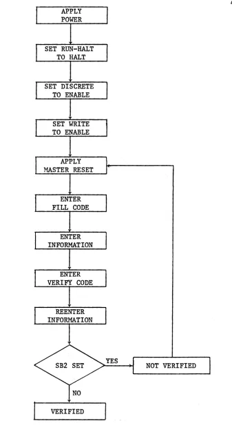
The following procedure must be performed to load program and data characters into the D17B Computer.
1. Apply power to the computer, cooling system, I/O devices, and the various interface units.
2. Set RUN-HALT to HALT.
3. Set WRITE to ENABLE if the write heads for channels 00 through 46 are to be enabled. Set DISCRETE to ENABLE if the write head for channel 50 is to be enabled. In most cases these will always be set to ENABLE, or they may be hard-wired to ENABLE.
4. Push MASTER RESET and release it. The I-register (or loop) should read 50000000.
5. Enter a FILL code.
6. A sequentially addressed block of information representing data and/or instructions may be entered into memory as follows:
7.
(a) Enter the 4-digit octal location which represents the first address of the block of information. This will be loaded into the right-most digits of the register. A CLEAR code can be used to clear the L-register~ but this is not necessary. The character presently being loaded will appear as the right-most digit of the L-register. The previous contents will be shifted one digit to the left with the left-most digit being shifted out as an overflow.
(b) Enter a LOCATION code. The first address location will now appear in the right-most half of the I-register.
(c) Enter the 8-digit octal data or instruction word into the L-register. Cd) An ENTER code will cause the contents of the L-register to pass through
the A-register and be stored in the memory address location specified by the I-register contents. The address in the I-register will be incremented by one.
(e) For each additional sequential location, repeat steps (c) and (d). Repeated execution of step (d). will continue to increment the address. If the next location is not sequential, i.e., a new block of information is started, repeat the procedure listed in step 6.
8. To verify that the information has been properly entered into memory, a VERIFY code should be entered followed by a reloading of the program and data as in step 6. When the ENTER code is processed, Sb2 will set (which results in turning on the indicator light) if the contents of memory are different from the corresponding information being loaded.
APPLY POWER
SET RUN-HALT TO HALT
SET DISCRETE TO ENABLE
SET WRITE TO ENABLE
APPLY MASTER RESET
ENTER FILL CODE
ENTER INFORMATION
ENTER VERIFY CODE
REENTER INFORMATION
VERIFIED
NOT VERIFIED
<
[image:9.612.202.539.70.693.2]1.3 Sequence of Operations for the Compute Mode
The following procedure must be performed to execute a program on the D17B Computer.
1. Repeat steps 1 through 4 of the Load Mode procedure.
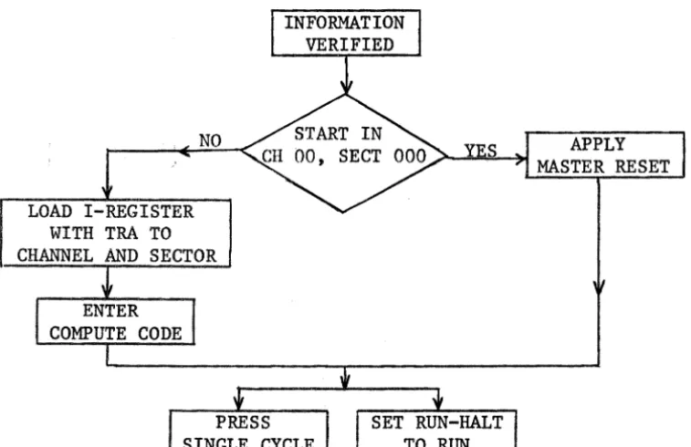
2. Place RUN-HALT in RUN. At this point the computer will automatically transfer to channel 00 sector 000 and begin execution. This process takes place because 50000000 was initially in the I-register after the MASTER RESET operation.
3. To manually start a program in another location than channel 00 sector 000, place RUN-HALT in HALT. Enter eight octal characters corresponding to a TRA, transfer instruction, to the location where execution is to begin. Enter the LOCATION code and the COMPUTE code.
4. When RUN-HALT is placed in RUN, execution will begin at the desired memory location.
5. For single cycle operation perform the procedure listed in step 1 or 3 depending on the location where execution is to begin. If the starting location is channel 00 sector 000, then proceed to step 1. Otherwise, start with step 3. One instruction will be executed each time SINGLE CYCLE is depressed.
If it is desired to automatically execute a program which starts in a location other than channel 00 sector 000, then a TRA instruction to the desired channel and sector can be loaded in channel 00 sector 000. A flow chart for this sequence of operations is shown in Figure 1-2.
NO
LOAD I-REGISTER WITH TRA TO CHANNEL AND SECTOR
APPLY MASTER RESET
[image:10.617.117.496.456.701.2]1.4 Minuteman D17B Computer Checkout Procedure
Before turning on the computer, check to see that all cables appear to be connected properly. After the computer has been inspected, begin the following checkout procedure. The left column gives the procedure to be followed, and the right column shows the correct status of the system. If the system does not show the same status as given here, turn off the computer and repeat the steps listed here again. Wait for at least two minutes before turning on the computer again. If the system still operates incorrectly, the trouble-shooting procedures should be followed.
PROCEDURE
1. Place the ON-OFF switches for all power supplies and I/O equipment to OFF.
2. Provide the necessary power line voltages.
3. Place RUN-HALT in HALT.
4. Place the 28 V Power Supply ON-OFF switch in the ON position. Turn on all I/O equipment and the related interface units.
5. Press MASTER RESET and FILL. 6. Press CLEAR.
7. Press LOCATION. 8. Press ENTER.
9. Press in sequence the keys for 0, 1, 2, 3, 4, 5, 6 and 7.
SYSTEM STATUS
The memory motor should rotate. The ammeter on the 28 V Power
Supply should indicate approximately 20 A initially. It will then drop to approximately 18 A.
I-register shows 50000000. L-register shows 00000000. I-register shows 00000000. A-register shows 00000000.
I-register advances one count, i.e., it shows 00000001.
L-register shows 01234567.
CHAPTER 2
0178 PROGRAMMING TECHNIQUES
2.1 Minimal Delay Coding (MDC)
The location of successive instructions and their operands is extremely important because these locations are arranged serially within the various channels on the disc. With MDC an instruction can be completed in the number of word times equal to the basic execution time of that instruction. There-fore, to execute a number of sequential instructions in the minimum number of word times, the instructions should be separated by n-l sectors where n is the basic execution time of the first instruction of each pair of these instructions. For MOC, it is always preferrable to have the operand availa-ble on the next sector following the location of this first instruction.
A few pertinent comments concerning MOC are listed in the following: a) It will be desirable to utilize flag storing and the rapid-access loops as much as possible. These loops are the U-Ioop for one word (Unit), the F-Ioop.for four words (Four), the E-Ioop for eight words (Eight), and the H-Ioop for sixteen words (Hexadecimal). The V-loop and the R-Ioop are two additional four-word rapid-access loops. While it is not possible to flag store to these loops, the standard STO instruction may be used. Data may be stored in either full or split-word format in the V-loop. However, data may only be stored in the split word format in the R-Ioop. Also, the left or most significant half of R.O is not available for data storage. It will usually be required to reserve the L-Ioop for temporary data storage,
for use with the ANA instruction, and for multiply operations.
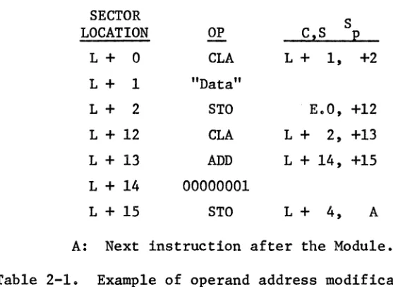
consideration can serve as a guideline. The WC consideration is to assure MOC for the worst possible operand location. Therefore, there will be no delay equal to a disc revolution in any case. Caution must be observed con-cerning the distance between the location of instructions with modified addresses and the locations of the next instructions to be executed. It is always appropriate to make the distance between these instructions at least equal to the word-length of the specific loop used if the full loop is to be involved. If only a portion of a loop is involved, a similar WC considera-tion can also be applied. The example shown in Table 2-1 illustrates this technique in detail.
SECTOR S
LOCATION OP CzS p
L+ 0 CLA L+ 1, +2
L+ 1 "Data"
L+ 2 STO E.O, +12
L + 12 CLA L+ 2, +13 L + 13 ADD L+ 14, +15 L+ 14 00000001
L+ 15 STO L+ 4, A
A: Next instruction after the Module. Table 2-1. Example of operand address modification.
[image:13.613.152.431.324.527.2]sense have been preserved.
2.2 Optimum Storage Programming
Minicomputers such as the Dl7B have small memories. It will therefore be desirable to make full use of the available memory in a sophisticated Dl7B program. Utilization of the rapid-access loops is one of the most important quidelines for optimum storage programming. There are also other considerations such as the following:
9
a) Use of the same channel for instructions and data storage provides for efficient use of memory. The next sector can normally be used for data, and the following sector can be used for the location of the next instruction. Unless minimum execution time is of extreme concern, this programming tech-nique is desirable because it will not waste any of the available memory.
It also offers the advantage of keeping track of the data in the same channel as the instructions. In this manner, memory space can be saved; but longer execution time will be the trade-off.
b) It is desirable to avoid transferring to locations with sector addresses that are less than the present address unless a program loop is encountered. It is permissible to leave certain memory locations vacant to satisfy MOC. These locations can often be used for other portions of the program. This offers memory saving, equalization time, and often time saving as well.
2.3 Scaling of Constants
Data are expressed in the fractional binary form in the DI7B. The fixed binary point is located between T24 and T23 for the full-word data format; the two fixed binary points for the split-word data format are located between T24 and T23 and between TIl and TIO ' However, if it is necessary
Scaling must be considered whenever a multiplication or a division is involved. If the binary point has been interpreted by the programmer as being located n-bits to the right of the original position, then he should shift the product left by n-bits on multiplication, and the quotient should be shifted n-bits to the right on division.
The binary point for a 24-bit data word can be assumed to be located in any position. If, for example, it is located between T12 and T13 , this will provide a total of II-bits for the integer portion, l2-bits for the fractional portion, and one sign bit. The rules for floating point multiplication and division are applicable to the binary number system also. This scaling tech-nique will be helpful in manipulating and interpreting data.
When a multiplication operation is executed using scaled data in the configuration specified previously, an II-bit left-shift must be applied to the product. If a division operation is executed, an II-bit right-shift must be applied to the quotient. The required shift can be partially or totally executed on the two operands as well as on the result of the multi-plication or division operation as long as the sum of the bit-shifts equals the total number of required shifts. For instance, in the previous example, a 2-bit left-shift for the multiplicand, a 3-bit left-shift for the multi-plier and a 6-bit left-shift for the product will yield a total of an II-bit left-shift and produce the correct binary point interpretation for the true product. It is preferable to shift, at least partially, in advance to prevent data overflow or underflow.
2.4 Codin&. Examples
Programming is commonly accomplished using the basic D17B machine lan-guage instructions. DI7B instructions are three-address instructions; i.e., each instruction contains the location of the next instruction, the flag storage location, and the operand location. Dl7B programming is a somewhat unique experience. It may seem tedious and time-consuming at first by some. However, after becoming familiar with the instruction set and the programming techniques, the programmer will find D17B programming to be an enjoyable experience. Increased program execution speed and memory saving are two distinct advantages of machine language programming. The D17B instruction set and some preliminary programming techniques have been presented previously in the DI7B Programming Manual, Report MCUG-4-71.
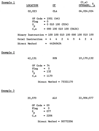
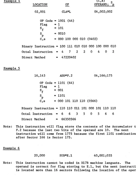
Three coding examples are shown in Table 2-2 for unflagged instructions, and three more are shown in Table 2-3 for flagged instructions. Examples
1, 3, and 4 illustrate MDC. 2.5 Flag Store Codes
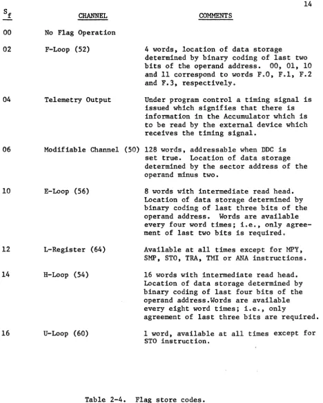
The Dl7B has a "flag store" mode which provides for simultaneously
storing the previous contents of the Accumulator in certain specified channels coincident with the execution of an instruction. This feature eliminates the need for an additional instruction to perform this frequent operation. Some comments concerning these flag store codes are listed in Table 2-4.
2.6 Exceptions for Instruction Codes
The complete instruction set has been illustrated in the Dl7B Programming Manual, Report MCUG-~,-7L There are certain exceptions for specific instruc-tions which, i f ignoredt may lead to faulty results or inappropriate computer
12
ExamE1e 1 (C,s)
S
LOCATION OP OPERANDi E
02,023 CLA 04,024;024
OP Code
=
1001 (44) Flag=
0S = 0 010 100 (024) p
C,s
=
000 100 010 100 (0424)Binary Instruction
=
100 100 010 100 000 100 010 100Octal Instruction
=
4 4 2 4 0 4 2 ·4Direct Method = 44240424
ExamE1e 2
42,131 SUB 10,170;132
OP'Code
=
74Flag
=
0S
=
132p
e,s
=
1170Direct Method
=
75321170ExamE1e 3
20,070
ALS
22,006;077OP Code
=
00Flag
=
0S
=
077p
C,s
=
2206Direct Method
=
00772206 [image:17.613.81.489.77.616.2]Example 4
Example 5
LOCATION OP
02,001 CLA*L
OP Code
=
1001 (44) Flag - 1Sf
=
101 S=
0010p
(C,s) S OPERAND; p 04,002;002
C,s
=
000 100 000 010 (0402)Binary Instruction
=
100 111 010 010 000 100 000 010 Octal Instruction=
4 7 2 2 0 4 0 2 Direct Method=
4722040216,143 ADD*F.2 04,166;175
OP Code
=
1101 (64) Flag=
1Sf
=
001 S=
1101p
C,s
=
000 101 110 110 (0566)Binary Instruction
=
110 110 011 101 000 101 110 110 Octal Instruction = 6 6 3 5 0 5 6 6 Direct Method=
66350566Note: This instruction will flag store the contents of the Accumulator to F.2 because the 'last two bits of the operand are 10. The next instruction will come from 1775 because the first 1101 combination after Sector 166 is Sector 175.
Example 6
20,000 SUB*E.1 40,,001 ;035
13
Note: This instruction cannot be coded in D17B machine 1anguate. The operand is correct for flag storing to E.l, but the next instruction is located more than 16 sectors following the location of the operand.
[image:18.617.70.525.84.680.2]00 02
04
06
10
12
14
16
CHANNEL No Flag Operation F-Loop (52)
Telemetry Output
14 COMMENTS
4 words, location of data storage
determined by binary coding of last two bits of the operand address. 00, 01, 10 and 11 correspond to words F.O, F.l, F.2 and F.3, respectively.
Under program control a timing signal is issued which signifies that there is information in the Accumulator which is to be read by the external device which receives the timing signal.
Modifiable Channel (50) 128 words, addressable when
nnc
isE-Loop (56)
L-Reg;i.ster (64)
H-Loop (54)
U-Loop (60)
set true. Location of data storage determined by the sector address of the operand minus two.
8 words with intermediate read head. Location of data storage determined by binary coding of last three bits of the operand address. Words are available every four word times; i.e., on1yagree-ment of last two bits is required.
Available at all times except for MPY, SMP, STO, TRA, TMI or ANA instructions. 16 words with intermediate read head. Location of data storage determined by binary coding of last four bits of the operand address.Words are available every eight word times; i.e., only
agreement of last three bits are required. 1 word, available at all times except for
STO instruction.
[image:19.615.97.566.67.653.2]INSTRUCTION
MPY, SMP
ANA
COA
EXCEPTIONS
The L-Register is not available for a flag instruction.
The L-Register is not available for a flag instruction
This instruction is not defined when s is zero.
TRA Channel address cannot be 64(L), 70(V), or
72(R) •
TMI Channel address cannot be 64(L), 70(V), or
72(R). When A > 0, all flag codes are defined only if MOC is used for TMI.
STO A-Register, L-Register, and U-Loop are not
available. Channels 00 through 46 are not available for EWC', and Channel 50 is not available for DDC Channel 50, the F-Loop, the E-Loop, and the H-Loop are not defined as operands for flagged instructions except for Sf
=
12 or 16.HPR MDC must be used.
Table 2-5. Exceptions for instruction codes.
16
2.7 Subroutine Linkage
In general, any program executed on a digital computer is composed of several previously written subroutines called in a proper sequence by a main program. Because the D17B does have limited memory capacity as is the case with most minicomputers, it may be both necessary and convenient to use the same subroutinerepeatedly, with different data values, in several steps during a particular program. Since it is unnecessary to duplicate the list of instructions in a subroutine each time it is used, a multiple subroutine linkage (MSL) must be developed so that the computer may execute the subrou~
tine one or more times during a particular program with one or more different data values.
In many programs executed on the D17B, one subroutine may be used at several different times during a particular program. The program executton time may be increased slightly if MSL is used, but this linkage technique is always desirable unless the execution time is a critical consideration. However, if the subroutine contains a small number of instructions, it then becomes questionable as to whether it is worthwhile to program a linkage and then transfer to the subroutine or to just repeat the instructions.
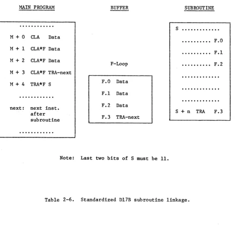
A MSt basically needs to perform three operations. First, it must give the subroutine any needed data values. Second, it must tell the subroutine where to return in the main program after it has completed its calculations. Finally, the linkage must transfer execution to the beginning of the subrou~ tine. The flag store capability of the D17B will aid in developing a concise linkage. The 4-word F-loop will be used as a buffer between the main program and the subroutine. Table 2-6 shows a block diagram of the proposed linkageo
MAIN PROGRAM
M+O CLA Data
M+1 CLA*F Data
M + 2 CLA*F Data M
+
3 CLA*F TRA-nextM
+
4 TRA*F Snext: next inst. after subroutine
...
BUFFER
F-Loop
F.O Data F.1 Data F.2 Data F.3 TRA-next
Note: Last two bits of S must be 11.
SUBROUTINE
s ... .
F.O F.l F.2S
+
n TRA F.3 [image:22.793.173.672.81.547.2]TUSL, into words 0, 1, and 2 of the F-loop via the flagged eLA instructions. This means that up to three input data words may be transferred from the main program to the subroutine. However, recall that the subroutine probably has access to many other data words which are fixed values (i.e. internal data which do not vary with input data) used for calculations internal to the sub-routine. It would also be possible to use a larger loop, say the E-loop or the H-loop, except that loading the data into the specific word within the loop might mean loss of memory space due to the necessary coding. Therefore, in some cases, the E- or H-loops might not be more economical, in terms of memory space~ than the normal eLA-STO, eLA-STO, ••• process.
After the data have been stored in words 0, 1, and 2 of the F-10op (represented as F.O, F.l, F.2), a TRA instruction is loaded into F.3. The operand of this instruction will be the location of the next instruction after the subroutine has been completed. A TRA instruction to the beginning of the subroutine concludes the call sequence. It is important to note that this TRA instruction may actually be used to flag store the accumulator. As shown in Table 2-6, the TRA instruction in location M+4 flag stores the TRA-next to word F.3. This means that the linkage is five instructions compared to nine
for the eLA-STO, eLA-STO, ' 0 ' method.
19
execution back to the proper location in the main program. If used cons is-tantly, MSL should prove to be efficient.
For the non-multiple modular cases, i.e., none of the various subrou-tines will be utilized repeatedly, linkage simply means to chain appropriate modules as specified by the program flow chart. Typical modules are given in Chapter 3. Programwise, this can be achieved by designating the next instruction location for the last instruction of the previous subroutine or module to be the starting location of the later subroutine or module. The
complete Non-Multiple Modular Linkage (NML) can be assembled in the same manner.
2.8 Address Modification
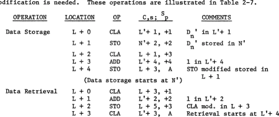
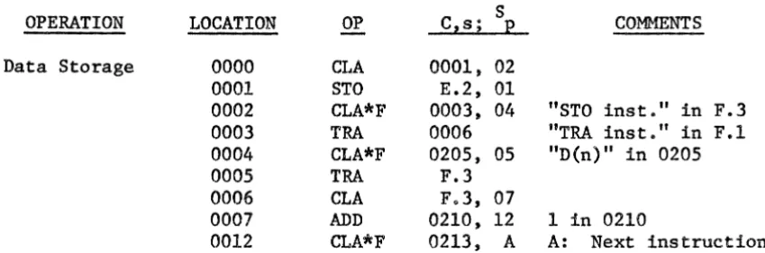
The disc memory of the D17B is used for the storage of both data words and instructions. It is this feature which makes address modification possible. When a series of data values are operated on consecutively by a certain arithmetic operation, address modification becomes very desirable for the sake of program-simplification. In performing address modification, the instructions are regarded as data words which can be modified as needed. Data storage and retrieval are typical examples of situations where address modification is needed. These operations are illustrated in Table 2-7.
OPERATION LOCATION OP C,s; S p COMMENTS L + 0 CLA L'+ 1, +1 D ' in L'+ 1
n Data Storage
L
+
1 STO N'+ 2, +2 D ' stored in N' nL + 2 CLA L
+
1, +3L + 3 ADD L'+ 4, +4 1 in L'+ 4
L+4 STO L + 3, A STO modified stored in (Data storage starts at N') L+l
Data Retrieval L + 0 CLA L+ 3, +1
L + 1 ADD L'+ 2, +2 1 in L'+ 2
L
+
2 STO L+ 5, +3 CLA mod. in L + 3L
+
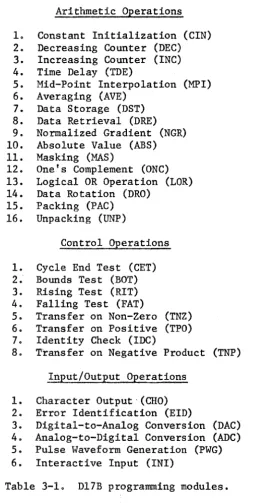
3 CtA L'+ 3, A Retrieval starts at L'+ 4 [image:24.613.86.541.520.711.2]20 In the examples shown in Table 2-7, MDC has only been preserved for certain data values. This may be undesirable for those cases where timing is a critical consideration. Address modification can be accomplished in these cases by using the rapid-access loops. The examples in Table 2-8 show how data storage or data retrieval can be achieved without excessive delays of several disc revolutions.
OPERATION LOCATION OP Data Storage 0000 CLA
0001 STO
0002 CLA*F
0003 TRA
0004 CLA*F
0005 TRA
0006 CLA
0007 ADD
0012 CLA*F Note: 0000 through 0004 only
Data Retrieval 0000 CLA
0001 CLA
0002 CLA*F
0003 TRA
0004 CLA*F
1002 CLA
1003 ADD
1006 STO
1007 TRA
C,s; 0001, E.2, 0003, 0006 0205, F.3 F.3, 0210, 0213, S p 02 01 04 05 07 12 A COMMENTS
"STO inst." in F.3 "TRA inst." in F.1 "D(n)" in 0205
1 in 0210
A: Next instruction for initialization.
0001, 02 E.l, 01
0003, 04 "CLA inst." in F.3 A A: Next instruction 0205, 05 "D{n)" in 0205
F.3, 03
0204, 06 1 in 0204 F.3, 07
F.3
Note: Channel 00 only for initialization. Data retrieval starts at E.2.
[image:25.615.94.519.218.358.2]21
CHAPTER 3
D17B PROGRAMMING MODULES
There are a total of 39 instructions available for Dl7B programming.
Although the instruction set is relatively small compared to that available
with large-scale general-purpose computers, this instruction set is quite
sufficient if the instructions are used appropriately. The concept of a
"Module" has been created in the Tulane Systems Laboratory through experience
gained in D17B programming. Here, modules, each of them a set of several
instructions, represent different arithmetic calculations or logic operations
which are useful in Dl7B programming. Each module may be equivalent to more
than a single instruction used with a more sophisticated computer or a higher
level programming language.
Programmers are always urged to draw a flow chart before writing any
program. Furthermore, it is suggested that flow charts be prepared in such
a manner that the module set can be used to realize each block of the flow
chart. Considerable experience has shown that~ in most cases, flow chart
blocks can always be realized using a set of typical modules. Of course,
the size of module block can be extended, in the limit, to the complete flow
chart itself. The usefulness of the respective module will then be limited,
however, because of the lack of repeatability.
The modules can usually be divided into three categories which are the
Arithmetic Operations, Control Operations, and Input/Output Operations. The
most useful modules within each category based on experience in the Tulane
Systems Laboratory are listed in Table 3-1. The mnemonic symbol for each
module is shown in parentheses. The explanations and instruction listings
for the various modules are given starting in Section 3-1. Since the modules
22 which are designated with letters such as L, A, B, C, etc., are used in the standard format notation.
It is the responsibility of the programmer to assure that MDC is pre-served. Throughout this Chapter, Land L' represent memory locations with identical sector numbers. Familiarity with the module set is just as signif-icant as familiarity with the instruction set and is strongly recommended.
Arithmetic Operations 1. Constant Initialization (CIN) 2. Decreasing Counter (DEC) 3. Increasing Counter (INC) 4. Time Delay (TDE)
5. Mid-Point Interpolation (MFI) 6. Averaging (AVE)
7. Data Storage (DST) 8. Data Retrieval (DRE) 9. Normalized Gradient (NGR) 10. Absolute Value (ABS) 11. Masking (MAS)
12. One's Complement (ONC) 13. Logical OR Operation (LOR) 14. Data Rotation (DRO)
15. Packing (PAC) 16. Unpacking (UNP)
Control Operations
1. Cycle End Test (CET) 2.' Bounds Test (BOT) 3. Rising Test (RIT) 4. Falling Test (FAT)
5. Transfer on Non-Zero (TNZ) 6. Transfer on Positive (TPO) 7. Identity Check (IDC)
8. Transfer on Negative Product (TNP) Input/Output Operations
1. Character Output,(CHO) 2. Error Identification (EID)
3. Digital-to-Analog Conversion (DAC) 4. Analog-to-Digital Conversion (ADC) 5. Pulse Waveform Generation (PWG) 6. Interactive Input (INI)
[image:27.617.188.463.231.734.2]23 3.1 Arithmetic Operations
CIN Constant Initialization
This is used for initializing the constants at the beginning of a program.
SECTOR
S
LOCATION OP C,S
P
L + 0 CLA L'+
I,
+1 L + 1 CLA*L L'+ 2, +2 L + 2 CLA*U L'+ 3, +3 L + 3 CLA*F L'+ 4, +4 L + 4 CLA*F L'+ 5, +5 L + 5 CLA*F L'+ 6, +6 L + 6 CLA*F L'+ 7, AL
+
7 < A < L+
26 DEC Decreasing CounterThe counter decreases 1 after the module is executed.
L
+
0L
+
1L
+
2CLA SUB STO
L'+ 1, +1 L'+ 2, +2
L
'+
3, AInitial count in L'+ 1 "1" in L'+ 2
A: Next instruction INC Increasing Counter
The counter increases 1 after the module is executed.
L + 0 CLA L'+ 1, +1 Initial count in L'+ L + 1 ADD L'+ 2 +2 "1" in L'+ 2
L + 2 STO L'+ 3, A A: Next instruction TDE Time Delay
3
+
DTime is delayed for 10(T + 128) ms where D is the sector distance between L + 2 and A.
L
+
0 L+
1L
+
2 MPI Mid-Point InterpolationCLA
SUB TMI
L'+ 1, +1 L'+ 2, +2
A, +1
"T" in L'+ 1 "1" in L'+ 2
A: Next instruction
This will perform the calculation D(n+l) = (D(n) + D(n+2»/2
L+ 0 CLA L'+ 1, +1 "D(n)" in L'+ 1 L + 1 ADD L'+ 2, +2 "D(n+2)" in L'+ 2
L+ 2 ARS 3201, +4
L+ 4 STO L'+ 5, A "D(n+ 1)" in L'+ 3 A: Next instruction
24
AVE Averaging
Depending on whether n is a Kth power of 2, different techniques are used in finding the average of a set of values.
L
+
0L
+
1L
+
k+
2CLA ARS STO
L'+ 1, +1 32(kR),k+2 L'+kT3, A
"Sum" in L'+ 1 "AVE" in L '+k+l A: Next instruction If n
~
2k, then the division subroutine should be used.DST Data Storage
A series of data values can be stored in consecutive locations by using address modification.
DRE Data Retrieval
L
+
0 L+
1L
+
2L
+
3L
+
4CLA STO
CLA
ADD STO
L'+ 1, +1 N'+ 2, +2 L + 1, +3 L'+ 4, +4
L + 3, A
"D(n)" in L'+ 1 "D(n)" stored in N' "1" in L'+ 4
A: Next instruction
This is the same as DST except that data are retrieved instead of stored.
L+O CLA L+ 3, +1
L + 1 ADD L'+ 2, +2 L + 2 STO L+ 5, +3 L + 3 CLA L'+ 3, A Data retrieval starts at L'+ 4.
NGA Normalized Gradient
The normalized gradient is the function increment.
ABS Absolute Value
L+O
L
+
1L
+
2CLA SUB STO
L'+ 1, +1 L'+ 2, +2
G
+
2, AA
=
-A if A < 0, but it is unchanged otherwise.L
+
0L
+
1L
+
2CLA MIM COM
L'+ 1, +1
4400, +2 4600, A
"1" in L'+ 2
"CLA inst." stored in L + 3
A: Next instruction
. "D(ri.+l)" in L '+ 1 "D(n)" in L'+ 2 G: Gradient storage A: Next instruction
25 MAS Masking
If certain bits of a word are to be preserved with the remainder of the bits being cleared, a masking technique can be used.
ONC One's Complement
L
+
0 L+
1L
+
2CLA CLA*L PJIA
L'+ 1, +1 L'+ 2, +2 4200, A
"Mask" in L'+ 1 "Data" in L'+ 2 A: Next instruction
Negative numbers are expressed in the 2's complement in the D17B. If the l's complement is desired, the following module is useful.
L
+
0L
+
1L
+
2L
+
3L
+
4 LOR Logical OR OperationCLA Data COM SUB 00000001
L + 1, +2 4600, +3
L + 4, A A: Next instruction
Two binary variables can be logically ORed as A + B
=
(A • B). L + 0 CLA A, +1 A: Data No. 1 L + 1 COM 4600, +2L + 2 SUB L + 3, +4 L + 3 00000001
L + 4 CLA*L B, +5 L + 5 COM 4600, +6 L + 6 SUB L + 7, +8 L + 7 00000001
L + 8 PJIA 4200, +9 L + 9 COM 4600, +10
L + 10 SUB L+ 11, C C: Next instruction L + 11 00000001
DRO Data Rotation
The locations of two respective data can be rotated using this module. L
+
0L + 1
L
+
2L
+
3L + 4
CLA CLA*U STO CLA STO
A, +1 B, +2 A + 2, +3 6000, +4
26 PAC Packing
UNP
This module packs an 8-bit right-justified word (x) into bits 9-16 of the U-loop. Two other 8-bit words were previously located in bits 1-8 and 17-24, and zeros were initially located in bits 9-16 of (x) and the U-loop.
L + 0 CLA L'+ 1, +1 (x) in L'+ 1 L + 1 ALS 2210, +12
L+ 12 ADD 6000, +13
L+ 13 STO L'+14, A Packed word in L'+12 A: Next instruction Unpacking
This module unpacks the middle 8-bit word from a word containing three 8-bit words. The word to be unpacked is assumed to be located in the U-loop, and the unpacked, right-justified a-bit word will be located in the Accumulator.
L + 0 L + 1 L
+
2 L + 3CLA CLA*L
ANA ARS
L'+ 1, +1
U, +2 4200, +3 3210, A
M1 in L'+ 1
A: Next instruction Ml = 00177400
3.2 Control Operations CET Cycle End Test
This module will check for the end of a loop-cycle.
L+ 0 CLA L'+ 1, +1 Counter in L'+ 1 L + 1 SUB L'+ 2, +2 "n" in L'+ 2 L + 2 TMI A, +3 DEC or INC in A L + 3 eLA L'+ 4, +4 Counter recovery L + 4 STO L'+ 3, A A: Next instruction BOT Bounds Test
This module tests fo~ the condition that a specific word is out of range with respect to upper and lower bounds.
L + 0 CLA L'+ 1, +1
L + 1 SUB L'+ 2, +2 "Max" in L'+ 2 L + 2 TMI L+ 3, +7
L+ 3 CLA L'+ 1, +4
L+ 4 SUB L'+ 5, +5 "Min" in L'+ 5
L+ 5 TMI L + 6, A A: Next instruction L + 6 CLA L'+ 7, E E: EID module
RIT Rising Test
This module
FAT Falling Test
This module
tests for a
tests L + 0 L + 1 L + 2
for a
L
+
0L
+
1 L+
2rising trend
CLA SUB TMI falling CLA SUB TMI trend
in a series
L'+ 1, +1 L'+ 2, +2 A, B
in a series
L'+ 1, +1 L'+ 2, +2 A, B
27
of data.
"D(n+1)" in L'+ 1 "D(n)" in L'+ 2 A: Next inst. if NO B: Next inst. if YES
of data.
"D(n+1)" in L'+ 1 "D(n)" in L'+ 2
A: Next inst. if YES B: Next inst. if NO
TNZ Transfer on Non-Zero
The module causes a transfer to a specific location if the contents of the Accumulator are non-zero.
L+ 0 CLA L'+ 1, +1
L+ 1 MIM 4400, +2
L+ 2 TMI A, B A: Next inst. i f
non-zero B: Next inst. if zero
TPO Transfer on Positive
The module causes a transfer to a specific location if A >
o.
L + 0 CLA L'+ 1, +1
L + 1 COM 4600, +2
L + 2 TMI A, B A: Next inst. if
A > 0 B: Next inst. i f
A < 0
IDC Identity Check
This module tests for the equivalence between two words.
L + 0 CLA L'+ 1, +1
L + 1 SUB L'+ 2, +2 "N" in L'+ 2
L
+
2 MIM 4400, +3L + 3 TMI A, B A: Next inst. i f NO
TNP Transfer on Negative Product
The module causes a transfer to a specific location if the product of two data values is negative.
L + 0 CLA L + 1, +2 L + 1 Data A
L + 2 CLA*L L + 3, +4 L + 3 40000000
L + 4 ANA 4200, +5 L + 5 ADD L + 6, +7 L + 6 Data B
L + 7 TMI C, D C: Next inst. if A"B < 0 D: Next inst. if
A·B > 0 3.3 Input/Output Operations
CHO Character Output
This module transfers the contents of a specific word into the voltage output register and initializes the teletype to print out the character with ASCII Code corresponding to bits 17-24 of the A-register.
L
+
0 L+
1L
+
2 L+
3 EID Error IdentificationCLA VOA DOA DOA
L'+ 1, +1 3000, +2 2613, +3
2600, A A: Next instruction
An error code will be printed when an error is detected, and the buzzer will be sounded using this module.
L+O CLA L'+ 1, +1 Error code in L'+ 1 L + 1 STO L'+ 2, +2
L + 2 DOA 2610, +3 Buzzer is pulsed L + 3 DOA 2600, +4
L
+
4 HPR 2200, +5L + 5 TRA CHO, A A: Next instruction DAC Digital-to-Analog Conversion
The analog voltage output corresponding to certain digital information is made available.
L
+
0 L+
1L
+
2LPR CLA VOA
7020, +1 L'+ 2, +2 3400, A
Set P3
29 ADC Analog-to-Digital Conversion
This module pulses the A~l> converter and inputs the digital data to the D17B.
L
+
0L
+
1L
+
2 PWG Pulse Waveform GenerationDOA DOA DIB
2620, +1 2600, +2 5000, A
Pulse A-D converter A: Next instruction
This module causes the data (x) to be counted up or down depending on whether (x) is negative or positive respectively. Then (x) will switch between 00000000 and 77777777 thus generating a pulse train with pulse width of 10 ms and a period of 20 ms.
INI Interactive Input
L + 0
L
+
1CLA BOA
L'+ 1, +1 1000, +1
This module inputs an 8-bit character from the peripheral I/O device under program control. X8C - XlC are connected to the 8-bit character information lines. X9C is connected to the character ready line.
L + 0 CLA L + 1, +2
L + 1 00000400 1 in bit 9
L + 2 DIA*L 5200, +3 X9C-XlC -+ Accumula-L + 3 ANA*U 4200, +4 Mask A9 tor L + 4 SUB L + 5, +6
L +
5
00000400 1 in bit 9L + 6 TMI L + 0, +7 Was X9C
=
I? L+
7 DOA 2616,+10 Reset Ready Line L +10 DOA 2600, A A: Next Instr.CHAPTER 4
017B SUBROUTINES
Various subroutines which have been useful for D17B programming have
been developed by the staff of the Tulane University Systems Laboratory (TUSL).
Each subroutine can be considered as an independent program which will
exe-cute a specific operation. The standardized subroutine linkage technique is
illustrated in Section 2.4. As long as the subroutine linkage is
appropri-ately established, the various subroutines can be used repeatedly.
A division instruction is not available as a hardware feature of the
D17B. This deficiency can be remedied either software- or hardware-wise.
The Von Neumann division subroutine has been developed in the TUSL for this
purpose. The subroutines listed in this chapter are available for various
versions of input/output interfaces to MCUG members as part of the
informa-tion exchange program.
Section 4.1 describes in detail a software addition to the overall D17B
checkout procedure. Full documentation is included on this subroutine since
it is believed to be of importance to all users of the D17B. The sections
which follow give brief descriptions of the various other subroutines that
have been developed in the TUSL. Since all MCUG members will not desire
full documentation on each of these subroutines, additional information on
these subroutines will be made available on an exchange basis.
4.1 Exhaustive D17B Diagnostic Program
Because of the D17B's multi-channel disc memory, it is not sufficient
to check the functional capabilities of the computer in one area of memory
if a complete software diagnostic test is desired. For this reason, a new
phase has been added to the diagnostic and checkout procedure--the Exhaustive
31 checked out in one area of memory, it is not necessary to check each of the capabilities in each memory location. The reason for this is that the
execution of instructions is performed using fixed logic, and this logic is, in general, not dependent on the channel or sector location of the instruction to be executed. The operations which will be tested exhaustively by the EDP are the following.
1) The ability to store data in each location. 2) The ability to retrieve data from each location.
3) The ability to unconditionally transfer to each location.
4) The ability to execute a flagged instruction in each location. The next instruction sector after this flagged instruction must be correct. These four operations include a test of all the location dependent hardware in the Dl7B including all channels of the disc memory. The EDP will use address modification to perform the exhaustive test. The controlling program will be loaded in channel 00 after the functional capabilities of this channel are diagnosed. Therefore, if trouble results, the controlling program can be eliminated as the source of the trouble. A flow chart for the EDP program is shown in Figure 4-1. The program is broken into two main portions. The first section loads all 128 sectors from channel 04 through channel 50 with their respective addresses. That is, channel 32, sector 105 would contain an octal 00003305 at the end of this portion of EDP. These values will be used as indicators later in the second portion of the program.
The D17B will halt after it has loaded all sectors with the proper data. Since each location contains its absolute address, the program may be halted at this point for diagnosis of display hardware. The second portion of the program uses address modification to place the group of three instructions, shown below, sequentially through the memory.
C, s
+
0 CLA C+
2, s+
1 C, S+
1 CLA*U C+
2, s+
2 C, s+
2 TRA Control Program( START
)I_~L...--""'---'
(
CLA A
STO A
YES
HPR
_Porti~l=yo~Sec~~ _ _ _ _ _ _ _ _ _ _ _ _ _ _ _ _ _
Portion 2 -- Execute 3-instruction Groups
A
=
C, s C=
02 s=
000YES C
=
C+
2s
=
000STOP
~~E
____~Y~E~S~.<
(Load Three Instructions) C,s
+
0C,s
+
1 C,s+
2CLA
CLA*U
TRA
C
+
2, s+
1C
+
2, s+
2Control Program
®
Where:
C
=
02 to 46 s = 000 to 177' - -_ _ _ - - - 1 - - -
~0
Fig. 4-1. Flowchart for exhaustive D17B diagnostic program (EDP).
[image:37.612.90.518.63.674.2]It is important to note that each time these three instructions are
stored in some group of sectors they will be executed immediately--before
the next group of three is stored. This will allow the programmer to monitor
the U-loop where he should observe a counter from 04tOOl through 50,177.
Since each group of three instructions is executed as it is stored, there
will be a sufficient time delay between changes in the U-1oop for the
pro-grammer to determine that each address (channel and sector) has been correctly
flagged. The time delay is determined by the time required for the control
program to construct the next group of three instructionst store them in the
proper locations, and execute them. Another important point is that, at any
one time during the second portion of EDP, the channel which is presently
being used as the data channel will contain the groups of three instructions
after the present instruction channel has been completely diagnosed.
Thereforet by placing these three instructions throughout the memory,
each sector of every channel is checked for the capability to transfer to it
from the control program, the capability to store data, the capability to
retrieve data from it, the capability to execute a flagged instruction, and
the ability to return to the controlling program. Thus, what started out to
be a flagged diagnostic program has proven its ability to test much more than
that, and it, therefore, deserves its title of EDP of the Dl7B Computer
Diag-nostic Testing Procedure. This program has been used to detect and assist
in correcting problems associated with the TRA and TMI instructions and with
external display equipment.
The program listing for EDP is shown in Table 4-1. No flagged
instruc-tion is used in the controlling program. One of the major functions of EDP
is to test the flagged instructions; therefore, the controlling program should
34 Portion 1. Load sectors with addresses 0200-5177.
Location Contents °Eeration
0000 44020001 CLA 0001
0001 00000400 Data
0002 54040005 STO 0003
0003 00000000 Data
0004 44060005 CLA 0005
0005 00005177 Data
0006 74070003 SUB 0003
0007 10100021 TM! 0021
0010 44120011 CLA 0011
0011 54160002 Data
0012 64130003 ADD 0003
0013 54140017 STO 0015
0014 44150003 CLA 0003
0015 54000000 Data
0016 64200017 ADD 0016
oot7
00000001 Data0020 54040005 STO 0003
0021 44220022 CLA 0022
0022 40232200 HPR 2200
Portion 2. Place groups of three instructions from 0200-4777.
0023 442.50024 CLA 0024
0024 00000177 Data
0025 54270030 STO 0026
0026 00000000 Data
0027 44300026 CLA 0026
0030 64320031 ADD 0031
0031 00000001 Data
0032 55160030 STO 0026
0116 01172221 ALS 2221
0117 01203221 ARS 3221
0120 11230121 TMI 0121
0121 75230122 SUB 0122
0122 77777600 Data
0:1.23 75250124 SUB 0124
0124 00000174 Data
0125 11270126 TMI 0126
0126 44330026 CLA 0026
0127 45300026 CLA 0026
0130 01313207 ARS 3207
0131 01322207 ALS 2207
0132 65340133 ADD 0133
0133 00000200 Data
0134 54330030 STO 0026
0033 44350034 CLA 0034
0034 00004777 Data
0035 74360026 SUB 0026
[image:39.618.120.481.90.686.2]35
Location Contents Operation
0036 10370114 TMI 0114
0037 44410040 CLA 0040
0040 54670002 Data
0041 64420026 ADD 0026
0042 54430070 STO 0066
0043 44450044 CLA 0044
0044 55030003 Data
0045 64460026 ADD 0026
0046 54470104 STO 0102
0047 44510050 CLA 0046
0050 55060004 Data
0051 64520026 ADD 0026
0052 54530107 STO 0105
0053 44540026 CLA 0026
0054 64560055 ADD 0055
0055 00000001 Data
0056 00572221 ALS 2221
0057 00603205 ARS 3205
0060 10630061 TMI 0061
0061 74630062 SUB 0062
0062 76000000 Data
0063 64640026 ADD 0026
0064 64660065 ADD 0065
0065 44000201 Data
0066 54670000 STO XXXX
0067 44700026 CLA 0026
0070 64720071 ADD 0071
0071 00000002 Data
0072 00732224 ALS 2224
0073 00743210 ARS 3210
0074 10770075 TMI 0075
0075 74770076 SUB 0076
0076 77600000 Data
0077 65000026 ADD 0026
0100 65020101 ADD 0101
0101 47600202 Data
0102 55030000 STO XXXX
0103 45050104 CLA 0104
0104 50000027 Data
0105 55060000 STO XXXX
0106 45100107 CLA 0107
0107 50000000 Data
0110 65110026 ADD 0026
0111 55120115 STO 0113
0112 45130113 CLA 0113
0113 50000000 TRA XXXX
0114 45150115 CLA 0115
0115 41162200 HPR 2200
[image:40.613.149.456.75.682.2]36
The first portion of the test occupies sectors 000 through 022 of channel 00. This portion causes all channels to be loaded as discussed
previously. The execution of this portion takes approximately three minutes. The second portion of EDP is loaded in sectors 023 through 134 of channel 00. This portion causes the groups of three instructions to be loaded and then transfers execution to each group as it is loaded. Execution time for this portion is approximately 12 minutes. The total time for execution of EDP is approximately 15 minutes. If the operator notices that the U-loop stops counting or if it counts in the wrong order, he should abort the program, find the present contents of the address counter, and begin to narrow the problem down under Single Cycle control in the range of locations where the problem occurred.
The combined use of functional checkout and EDP should provide the Dl7B status at any given time. If the Dl7B can execute EDP without an error, it is highly probable that the computer is completely in a "go" condition. 4.2 8-bit VOA Character Output
This subroutine sends an 8-bit data word to the Voltage Output A (VOA) register and causes the output device to print. The subroutine can transfer any size data block from any memory area to the output device. In general, it may also be used to transfer any number of 8-bit parallel words to an external or peripheral I/O device.
4.3 Octal Contents Output
This subroutine causes the peripheral I/O device to print the octal contents of the specified memory location. It j.s optional whether the sign will be printed.
4.4 Memory Dump Routine
In programming the Dl7B it is often convenient to obtain the actual contents of some group of locations in memory. This program will cause a block of data from any portion of memory to be printed. Both the location and the contents of each location will be printed. The printout is achieved using the VOA subroutine described in Section 4.2. The location and size' of the block are entered using an interactive technique. This technique is
37 4.5 Waveform Generation
Digitized representations of analog waveforms are prestored in the D17B memory. These data are then brought to the voltage output register and sent to one of the D-A converters at the proper time.
4.6 Linear Interpolation
This subroutine linearly interpolates between specific data values to obtain the value corresponding to some unknown data. The required division operation in this subroutine is achieved by using the Von Neumann division subroutine.
4.7 Linear ScalinA
This subroutine scales a series of data linearly by applying linearly weighted increments to these data.
4.8 Accumulator N-bit Rotation
This subroutine causes the contents of the accumulator to rotate right/ left for n bits. Here rotation means that the contents are shifted while the information is preserved. The variable n can be any number.
4.9 Accumulator Bit Reversal
This subroutine reverses the contents of the accumulator bit-by-bit (i.e. A24 -+ A1, A23 -+ A2, etc.) and preserves the original data order in the lower accumulator.
4.10 Logic EXCLUSIVE OR Operation
The corresponding bits of the two specified memory locations are logically EXCLUSIVE ORed. The result is stored in the accumulator.
4.11 Binary-to-BCD Conversion
This subroutine converts any 10-bit binary number (0000 to 1747 octal) to the l2-bit BCD equivalent (000 to 999 decimal). The resulting decimal number can be printed on an output device.
4.12 BCD-to-Octal Conversion
This subroutine converts a Binary Coded Decimal number to its octal equivalent. The maximum BCD number allowed is 999999.
4.13 Von Neumann Division
4.14 Numerical Integration
This subroutine integrates the area under the digitized representation of an analog waveform which is inputed to the D17B using discrete input instructions. This subroutine may also be used to integrate the representa-tion of a waveform using data values that have been previously stored in memory. The trapezoidal rule of numerical integration is used.
4.15 Factorials
This subroutine calculates the factorial of any constant n. These
numbers are treated as integers, and the result is stored in the accumulator. 4.16 Reciprocal of a Constant
The reciprocal of a constant is calculated by using this subroutine. An iterative algorithm which calculates the next value from the previous value is used. Both positive and negative numbers are permissible. 4.17 Sin/Cos Routines
Separate subroutines are available for calculating Sin (x) and Cos (x). Series expansions of the respective trigonometric functions are used. The argument (x) is limited to the range of -1 to +1 radian. A subroutine which calculates Sin(x) and Cos (x) in the split word format is also available. A nesting technique is used in calculating the series throughout these examples.
-x
4.18 Negative Natural Exponential (e )
This subroutine calculates the negative natural exponential function by using the series expansion. The positive exponential function can be obtained by calculating the reciprocal. x must be less than unity.
4.19 Natural Logarithm 1n(x)
This subroutine calculates the natural logarithmic function. The value of the argument (x) is limited to positive values les~ than two.
4.20 Floating Point Multiply
This subroutine will mUltiply two floating point numbers. The two
mantissas are multiplied, and the exponents are added. Both fu11- and sp1it-word versions are available.
4.21 Floating Point ADD/SUB
A provision for floating point operations helps to give the Dl7B more complete arithmetic capability. Proper scaling is provided in the sp1it-word format.
4.22 Statistical Mean and Variance
39 4.23 Fast Fourier Transform (FFT)
This subroutine transforms a time-domain representation into its equiva-lent in the frequency domain and vise versa. The time series can be formed using a maximum of 128 data values. Extensions are under development. 4.24 Interactive Arithmetic
This subroutine can perform addition, subtraction, multiplication, and division through interactive communication between the D17B and the user. 4.25 Optimization
CHAPTER 5
40CORRECTIONS TO THE 017B PROGRAMMING MANUAL
Several additions and corrections to the D17B Programming Manual, Report
MCUG-4-7l, will be presented in this chapter. These additions and corrections
are listed corresponding to their page numbers as follows:
Page Line Addition/Correction
13 5 ••• the operand sector address. AZso~
in the case of a TRA
instruction~
both the next instruction sector address
andthe
sector of the designated /Zag Zoop wiZZ be determined by the
operand sector address.
29 15 If (c) is 50, F, E, or H, only L
or
U may be used for flag29
31
31
31
32
32
storing.
27 SMP Split Multiply 20 c,s 7 wdt
19
36
37