ARIX SYSTEMS CORPORATION
Site Preparation Manual
for the
Models 800 and 825
Part Number MA-99243-00
Revision A
Copyright 1989
Arix Systems Corporation, Inc.
821 Fox Lane
March 1989
FCC WARNING:
This equipment generates, uses, and can radiate RF (radio frequency) energy, and if not Installed and used in accordance with the information provided by ARIX, may cause Interference to radio communications. It has been tested and found to comply with the limits for Class A computing devices pursuant to Subpart
J
of Part 15 of FCC rules, which are designed to provide reasonable protection against such Interference when operated in a commercial environment. Operation of this equipment In a residential are. Is likely to cause interference, in which case the U8er, at his own ex-pense, will be required to take whatever measures may be required to correct the interference.Copyright <0 1989, ARIX Systems Corporation.
This document contains the latest information available at the time of preparation. Therefore, it may contain descriptions of functions not implemented at manual distribu-tion time. To ensure that you have the latest informadistribu-tion regarding levels of imple-mentation and functional availability, please consult the appropriate release documen-tation or contact your local GTE Spacenet Representative.
ARIX reserves the right to modify or revise the content of this document. No contrac-tual obligation by ARIX regarding level, scope, or timing of functional implementation is either expressed or implied in this document. It is further understood that in con-sideration of the receipt or purchaser of this document, the recipient or purchaser agrees not to reproduce or copy it by any means whatsoever, not to permit such ac-tion by others, for any purpose without prior written permission from ARIX.
Preface
Preface
This guide provides information and. recommendations to help prepare for the installation of the ARIX Model 800/825 system. It describes physical and functional characteristics of the host processors and includes information on planning the attachment of terminals, printers, modems, and other devices to be configured with the system.
All recommendations of this site preparation guide should be followed before the system is installed. Planning is important because, once the system is installed, it can be very difficult to make changes or to correct problems.
This guide is to be used in conjunction with the ARIX Installation and Maintenance Manual for the Models 800 and 825.
Table of Contents
Table of Contents
Section 1 Introduction... 1-1
CUSTOMER RESPONSIBILITIES . . . .• 1-1
TECHNICAL ASSISTANCE . . . • • . . . • . . • . • . . . 1-2
Section 2 System Planning . . • .. . . • . . . .. 2-1
SYSTEM COMPONENTS . . . • . • . . . .. 2-1
SITE PLANNING CONSIDERATIONS. . . • . . . • . . • . • . •• 2-4
Section 3 Site Environmental Planning . . . • . . . . .• 3-1
TEMPERATURE/HUMIDITY. . . • . . . • . . . .• 3-2
MEDIA STORAGE . . . : . . . • . . . -... 3-3
HEAT/SOUND OUTPUT. . . • . • . . . • . . . .. 3-4
ELECTROMAGNETIC INTERFERENCE . . . • . . . • .• 3-4
ELECTROSTATIC DISCHARGE . . . • . . . . • . • . •. 3-5
Section 4 Power Considerations . . . • . . . .• 4-1
VOLTAGE/FREQUENCY COMBINATIONS . . . • . . . . • 4-2
VOLTAGE/FREQUENCY VARIATIONS. . . • . . . •• 4-2 Voltage Variations. . . .. 4-2 Frequency Variations . . . .. 4-3
BRANCH CIRCUIT CONSIDERATIONS . . . • • • 4-3
POWER RECEPTACLES . . . • . . • • • 4-4
Section 5 Site Physical Planning . . . • . . . • . . . •• 5-1
PHYSICAL CHARACTERISTICS . . . • . . . .• 5-1
SPACE REQUIREMENTS . . . .. 5-2
FLOOR LOADING. . . .. 5-2
Section 6 Cabling Considerations . . . .. 6-1
CABLE LENGTH . . . 6-1
CABLE ROUTING . . . .. 6-1
Table of Contents
NOISE ENVIRONMENT . . . • . .. 6-2 CABLE TYPE. . . .. 6-2 EXISTING ON-SITE CABLES. . . .. 6-2 ARIX SYSTEM CABLES . . . .. 6-3 Section 7 Planning and Preparation Checklist . . . .. 7-1
Figures
Figure 4-1. Power Plug Diagram . . . 4-4
Tables
Table 3-1. Environmental Operating Limits . . . '. . .• 3-2 Table 3-2. Storage and Shipping Environmental Limits. . . • . • . .. 3-3 Table 3-3. Magnetic Media Storage Limitations . . . . . . .. 3-3 Table 3-4. Heat and Sound Output . . . D • • • • • • • • • • • • • • • • • 3-4 Table 4-1. Power Requirements. . . .. 4-1 Table 4-2. Voltage/Frequency Options. . . .. 4-2 Table 4-3. Voltage Variations . . . • . . . • . . . 4-2 Table 4-4. Frequency Variations . . . • . . . 4-3 Table 5-1 . Physical Characteristics . . . • . . . .. 5-1
Section 1
Section 1
Introduction
Introduction
This guide contains wiring, space, and environmental information to help the user prepare for the installation of an ARIX Models 800 or 825 system.
From this point on throughout this document, the Models 800 and 825 will be referred to as the Model 800/825.
The ARIX systems and the related peripherals are designed to be installed by the customer/user. If the installation site has any of the following unusual characteristics, contact an ARIX Customer Support Representative before beginning the installation.
• High or low humidity
• large temperature variations • Corrosive chemicals
• Contaminated atmosphere, especially conductive particles • Vibration
• High-altitude
CUSTOMER RESPONSIBILITIES
The customer has sole responsibility for meeting the electrical, environmental, and safety requirements of the system, and for operating in conformance with appropriate ordinances and building codes. A summary of customer responsibilities follows.
• Provide and install all communications cables, wall jacks, special connectors, and associated hardware.
• Provide and install all necessary power outlets\ distribution boxes, conduits, grounds, lightning arresters, and associated hardware.
• Make sure any building alterations are in accordance with local electrical and building codes, as well as meet environmental requirements of the system.
Introduction
Section
1
• Provide enough space for field service access to the system. Suggested clearance in front and in back should be 45 inches (114.3 cm). No clearance is required for either side.
• Provide appropriate safety measures, such as fire extinguishers and properly-sized circuit breakers. Do not use sprinkler systems for fire protection.
• When equipment arrives, unpack and inspect the equipment for damaged or missing items. While unpacking the system, if damage is evident or the shipment is not complete, do not proceed. Contact the shipper immediately and notify ARIX.
• Install the ARIX system and peripherals, and make the necessary cable connections to communications "equipment. Notify ARIX Customer Support immediately if there are any problems.
• Provide other equipment as required (for example, modems) and arrange for installation by the responsible vendor.
• Verify correct operation in accordance with instructions in the Installation and Maintenance Guide provided with the equipment.
• If an equipment failure occurs, use the checkout procedures in the Installation and Maintenance Manual to isolate and correct all possible malfunctions. If the system does not power up or a failure is indicated during the power-on confidence test, notify ARIX Customer Support.
• Notify an ARIX Customer Support Representative if equipment needs to be relocated or returned. Follow the instructions provided for repacking and relocation. Do not return equipment or components without an RMA (return materials authorization) from ARIX.
To avoid invalidating the warranty coverage or damaging the system beyond repair, contact ARIX Customer Support before installing or operating the system in a potentially hazardous or hostile environment.
TECHNICAL ASSISTANCE
Warranty and Support Agreement assistance for this product is available from ARIX Customer Support. All calls for support should be made directly to our support department:
• 800-237-2783 from outside California,
• 800-521-5783 from inside California, outside the 408 area code, or
• 408-432-1200 and ask for Customer Support.
Section 2
Section 2
System Planning
System Planning
The first step in planning the installation of the AR IX Model
800/825
is to become familiar with the terminals, printers, modems, and other equipment used in the system. In most cases, manuals for the devices are the best source of information. Understanding this equipment, especially its requirements and capabilities, will contribute to successful and efficient site planning. The next step is to identify the location for the system and to determine the requirements. This will ensure a quicker, easier installation .. It is especially important to determine data interconnect cabling requirements in advance to avoid installation delays. For example, some peripherals are supplied with interconnect cables and some are not. In some cases, standard-length cables' may not be the correct length or may be supplied with the wrong gender or type of connector. In addition, verify that signal pin definitions for peripherals and conductors used in the cables are compatible with those specified for the AR IX system (see Section 5 in the Installation and Maintenance Manual for the ARIX Models 800 and 825).
Make sure that the peripherals are supplied with the correct interface. Certain peripherals, notably printers, may not include an interface in the base price. In addition, the installation may require components such as line buffers or serial/parallel converters for best operation.
SYSTEM COMPONENTS
A basic ARIX system consists of the main cabinet, containing the CPU. The number and type of components, including terminals, printers, and system-related furniture is dependent on the needs of the user. The following is a summary of the various ARIX system modules:
CPU32
System Planning
Section 2
CPU32/25Mhz
The CPU32/25Mhz has 32-bit processing capabilities using a 25 Mhz 68020 microprocessor, a 64 kilobyte cache memory, full memory management and protection, 8K bytes of static RAM, and two 512 kilobyte EPROMS. The system architecture aUows a maximum of 2 of these boards to be running simultaneously in a single 800/825 system. These cards can only be installed into a system card slot intended for CPU or memory cards.
DMA MEMORY CONTROLLER
The Direct Memory Access (DMA) Controller provides all memory timing, refresh signals, access control (2 channels - DMC4/2), and error correction logic for the entire system. Each system requires one (and only one) of these boards.
MEMORY
There are two types of memory boards. The memory boards contain either 4, 8, 16, or 32 MB of error-correcting random access memory (RAM), using either 256K or 1 MB memory chips (depending on the board capabilities).
One type (older) uses the high density 256K dynamic RAM chips and can support either 4 or 8 MB of main memory. A system can have a maximum of 16 MB of main memory (two 8 MB boards) using this board. The other type (newer) uses the high density 1 MB dynamiC RAM chips and can support either 8, 16, or 32 MB of main memory. Using this board, a system can have a maximum of 64 MB of main memory (two 32 MB boards). A system containing the memory board populated with 1 MB chips
must
also contain the 25 Mhz Application Processor (CPU32/25) board.The memory board is arranged in 39-bit memory locations, where 32-bits are the actual data and 7 -bits are used to store the error correction information. The Model 800/825 can support up to 2 memory boards. The memory boards can only be used in slots which are reserved for'either CPU or MEMORY.
SYNC/ASYNC SERIAL I/O
The serial I/O board is an intelligent controller card capable of supporting up to 8 serial data I/O channels. A maximum of 2 serial channels can be synchronous, and the remaining serial channels are asynchronous. The 2 synchronous and 6 asynchronous channels can be used at the same time. Each channel can operate at a different baud rate ranging from 150 to 38.4K baud. This type of board has one 8 bit parallel port for a Centronics-type interface. A serial I/O board may only be placed into an Input Output Control Processor (IOCP) slot in the backplane, and requires an appropriate interface card.
Section 2
System Planning
DISK TAPE CONTROLLER - HSDT and EDT
The disk tape controllers support two SMD disk drives and a 9-track, 1/2~inch
magnetic tape, or four SMD disk drives and a 1/4-inch cartridge tape. The HSDT transfer rate is 1.8 megabytes per second. The EDT transfer rate of 2.4 megabytes per second supports faster disk drives. Disk tape controllers require an appropiate 9-track or cartridge interface card.
5 1/4 INCH SMD DISK DRIVE
The 800/825 accommodates up to three internal 5% inch SMD disk drives, each providing 172 MB of unformatted capacity.
QUARTER-INCH STREAMING TAPE
The Quarter-Inch Streaming Tape Drive is a 5% inch form-factor drive with a 45 MB or 60 MB (with a 600 ft. tape) formatted capacity.
POWER SUPPL Y
The power supply provides
+
5 V dc,+
12 V dc, and -12 V dc to the system.BA TTERY BACKUP
An optional accessory, the battery backup provides a measure of protection in the event of local power "brown outs" or short term power failures. It is capable of powering the entire system for up to 10 minutes and includes a built-in battery charger.
TERMINALS
Synchronous terminal connections require OB-25 pin connectors to the RS232C interface. Synchronous terminal ports can be used as asynchronous ports. Dedicated asynchronous ports on the 800/825 typically require DB-25 pin connectors on the termjnal end and
a
direct RJ 12/RJ 11 connection to the serial port.PRINTERS
System Planning
Section 2
MODEMS
A modem device can be attached to the ARIX system through the RS-232C serial interface only. Signal definition and pin usage may vary depending on the modem type. It is important that the cable between the modem device and the ARIX system be properly configured. In addition, the modem may require that various options or switches be set. Note that for modem operation, the output driver chips on the GCIIOCP can be switched. For detailed instructions, refer to the ARIX Installation and Maintenance Manual. The manual provided with the modem can also be referenced for more specific information.
SITE PLANNING CONSIDERATIONS
The ARIX system is designed to operate in a wide range of environmental conditions. Normally, little or no modification is required to existing office facilities to install and operate this equipment successfully. Nevertheless, in planning the installation, there are several important factors to consider:
• General environmental considerations, such as temperature and humidity (Section 3)
• Power requirements (Section 4)
• Space for and placement of the equipment (Section 5) • Cabling (Section 6)
A few additional factors to consider follow: • Cable Routing
It may be necessary to route signal cables through walls, ceilings, or false floors, especially if a number of peripherals at various places throughout the facility are to be installed. Installation of the system may be accomplished more readily if signal cables are installed first. These cables can be ordered separately and can be shipped in advance of the equipment.
Cable raceways or similar materials to protect loose cables that interconnect the equipment may be required. It is recommended that cable raceways or other materials are procured before the equipment arrives so they can be installed at the same time as the cables. ARIX supports a 50 ft. RS-232C cable for each connection to the system.
Section 2
System Planning
• Storage Facilities
When planning the installation, consider the possible need for additional storage facilities that may be required for reusable shipping containers, paper, ribbon, and printwheels. It is recommended that necessary supplies are on hand and ready for use when the equipment arrives.
Section 3
Site Environmental Planning
Section 3
Site Environmental Planning
The ARIX system is designed to operate in the typical range of environmental conditions found in many commercial office buildings. However, avoid installing this equipment in areas where adverse environmental conditions may exist.
DO NOT INSTALL THE SYSTEM IN THE FOLLOWING:
• Areas subject to extreme temperature or humidity variation.
• Kitchens, air-conditioner exhaust areas, or similar areas conducive to exceptional humidity.
• Line power networks that are subject to large voltage excursions. Typical examples of what not to have in the network are air conditioning systems, refrigeration units, or any type of highly inductive load that is cycled on and off periodically.
• Workshops or manufacturing environments producing high levels of airborne particles, such as dust, grit, smoke, or corrosive chemical agents.
• Basements or similar areas susceptible to flooding.
• Areas subject to electromagnetic fields or radio-frequency radiation.
• Areas subject to mechanical vibration or intermittent, high-g force excursions.
Site Environmental Planning
Section
3
TEMPERATURE/HUMIDITY
The ARIX system operates in a wide environmental range. It is designed to operate in the typical office environment under the same conditions as the people who use it. It is not recommended that the system be operated continuously at or near its temperature or humidity limits, or in a location where it is likely that these limits may be exceeded.
Certain combinations of temperature, humidity, and atmospheric pressure result in moisture condensing on surfaces in the system. This so-called "triple point" is typically well outside the range of conditions where the ARIX system is located, but if there is any doubt, wet-bulb thermometer readings should be taken and an operating curve plotted.
CAUTION
It Is particularly important to avoid operating the system in environmental conditions that may cause condensation. Even a small amount of moisture may result In a cataatroph-ic system failure.
The nominal operating temperature range is 21° to 27° centigrade (70° to 80° Fahrenheit), with a relative humidity range of 40 to 60 percent. When operating the equipment within this range, the operating safety margin effectively permits an extend-ed operating period in case of heating or air conditioning systems failure. Tables 3-1 and 3-2 specify the environmental limits of the System.
Table 3-1. Environmental Operating Limits
OPERATING RELATIVE
TEMP RANGE HUMIDITY ALTITUDE
SoC - 40°C 20% - 80%
4000 ft. (40°F - 102°F) (noncondensing)
Section 3
Site Environmental Planning
The nonoperating conditions (storage/shipping) of the system are:
Table 3-2. Storage and Shipping Environmental Limits
NONOPERATING TEMP RELATIVE HUMIDITY ALTITUDE TEMP RANGE CHANGE HUMIDITY CHANGE RANGE
-30°C to 60°C 10°C 50/0 to 950/0 100/0 Sea Level (-22°F to 140°F) per hour per hour to 40,000 ft.
(non-
(non-condensing) condensing)
MEDIA STORAGE
Store all media (backup tapes) under the environmental conditions recommended below. If these storage conditions are not possible, place the tapes in the same room as the system for at least one hour before using them to allow the tapes enough time to adjust to the temperature.
ARIX REVIEW COpy
Table 3·3. Magnetic Media Storage Limitations
MEDIA TYPE
Tape Cartridge
STORAGE TEMPERATURE
5°C - 45°C (41°F - 113°F)
3-3
STORAGE HUMIDITY
20% - 80%
(noncondensing)
Site Environmental Planning
Section 3
HEAT/SOUND OUTPUT
Table 3-4 shows the heat and sound output from each unit in the system.
Table
3-4.
Heat and Sound OutputUNIT SOUND
OUTPUT
HEAT OUTPUT
ARIX 800/825 CPU . 55 dBA 3300 BTU/HR.
9-Track (Cipher) 1160 BTU/HR.
Tape Drive
ELECTROMAGNETIC INTERFERENCE
As is true with most electronic equipment, electromagnetic fields or radiation emanating from radio, television, or radar antennas, may interfere with the ARIX system or its associated equipment.
Operating problems may also result from electromagnetic fields from industrial equipment such as arc welders, insulation testers, medical equipment, large high-voltage transformers, or similar equipment. Three-phase power distribution lines and related distribution panels, electric heating units, electric motors, and generators also may cause electromagnetic interference with the equipment.
To prevent such interference from causing problems, keep the equipment as far away from the sources of interference as possible. If this is not feasible, at least be aware of the potential problems.
Section 3
Site Environmental Planning
ELECTROSTATIC DISCHARGE
High electrostatic charges can build up as a result of people, equipment, or furniture in contact with carpeting or other types of floor covering. When these static charges are discharged into the metal of the equipment, desk, or table on which the equipment is located, interference with proper operation of the equipment may result.
Careful choice of furniture and use of coverings with antistatic properties should minimize static problems, as will the use of commercially available antistatic sprays on furniture and wall coverings. Electrostatic discharge is often a result of very low humidity, outside the recommended range of system operation.
If the system must be operated under conditions of very low humidity on a temporary basis, consider the following precautions:
• Wear only cotton clothing - no nylon or synthetic fabrics.
• Place conductive mats in front of the system and under each peripheral. Connect the mats to system ground.
• Before inserting a cartridge tape, touch the metal on the cartridge, and at the same time, something that is at system ground.
• Use anti-static spray as directed on the container.
Anyone in close proximity to a system should be properly grounded with a wrist strap or foot strap.
Section
4
Power Considerations
Section
4
Power Considerations
Specifying the primary input power voltage (115 or 230 VAC nominal) and frequency (50 or 60 Hz) is part of the ordering process for the ARIX system.- The system is then manufactured and tested to meet power requirements prior to shipment. ARIX recommends that circuits be used to provide primary power for this equipment in accordance with the following:
• 60 Hz, 15A, single pole, 115 or 230 VAC (± 100/0), single phase, 2-wire and ground
• 50 Hz, 15A, single pole, 115 or 230 VAC (± 10%
), single phase, 2-wire and
ground
Primary input power requirements for this equipment appear in Table 4-1:
Table 4-1. Power Requirements
UNIT PRIMARY INPUT
POWER
ARIX 800/825 (Fully configured) 1.2 KVA
Typical Dot Matrix Serial Printer 0.10 KVA Typical Correspondence Quality Printer 0.22 KVA
Typical Laser Printer 1.5 KVA
Typical Personal Computer 0.50 KVA
Power Considerations
Section 4
VOL TAGE/FREQUENCY COMBINATIONS
The ARIX 8001825 system is available to match voltage and frequency requirements for virtually any combination to be found worldwide. The following table shows the availability of various voltage and frequency options:
Table 4-2. Voltage/Frequency Options
Voltage Frequency
115 VAG (± 10%) 50160 Hz 230 VAG (± 10%
) 50/60 Hz
VOL TAGE/FREQUENCY VARIATIONS
The ARIX systems are designed to operate effectively despite significant variations that may occur in input voltage and frequency. Permissible variations are defined in the table that follows. If there are any concerns about voltage or frequency variations that may be experienced within the power network, contact the power company.
Voltage Variations
All component parts of the ARIX systems have been designed to function within the same limits of voltage variation, specifically. The ranges are shown in Table 4-3.
Table 4-3. Voltage Variations
Nominal Voltage Voltage Limits
115 VAG 92 to 132 VAG 230 VAC 187 to 264 VAC
Section
4
Power Considerations
Frequency Variations
All component parts of the ARIX system are tolerant of frequency variations within the limi.ts specified in the following table:
Table 4-4. Frequency Variations
Nominal Frequency Tolerance
47-63 Hz ±2 Hz
BRANCH CIRCUIT CONSIDERATIONS
Random or transient electrical noise in the power circuit can cause errors in data transmission. It is highly recommended that the specified power be provided from a branch circuit dedicated to the electronic equipment at site. Small equipment, such as terminals, modems, or printers may be powered from the same branch circuit. Large, high-current equipment, such as the main computer, expansion cabinet, and the laser printer, should have a separate, dedicated branch circuit.
To avoid introducing electrical noise into the system, other equipment (especially refrigerators, air conditioners, or heavy-current inductive motors) having an intermittent duty cycle should not be connected into the same branch circuit used for computer-related equipment. It is also recommended that the branch circuit being used either be equipped with a separate fuse or with an appropriate circuit breaker. This circuit should also be properly grounded. In some environments, a separate ground circuit may be required to eliminate "ground loops".
Power Considerations
Section 4
POWER RECEPTACLES
As part of the site planning, it is Important to ensure that power receptacles will accommodate the equipment and are close to the equipment. An appropriate power cable is supplied with most systems, as specified in the order.
The power cables supplied with the ARIX 800/825 series systems are polarized, 3-wire cables with a standard male connector for 60 Hz units. The 3-prong plugs are standard NEMA 5-15P and are for use in 3-wire circuits where one wire is ground. If the power cable on the equipment does not have a plug installed at the factory, make certain that during the installation the green/yellow wire in the power cable is connected to ground in the power circuit.
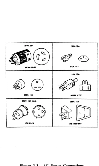
Refer to the Figure 4-1 to ensure that the receptacles are compatible with the plugs to be used with the equipment. If there are any questions concerning selection of the correct receptacles, contact an ARIX Customer Support Representative.
As in the United States, Canada, Japan, and Korea use a type A plug for 125 V power (see Figure 4-1). Other countries use 250 V. Most other countries use a type
8
plug. For some countries, plugs must be added by the customer.IIOV.IOA IRV. tOA
NEMA Ll-20 lEV t011
125V,1aA
2SOY, tlA NEMA I-tlP
HOV,
,.A
MAX. 2IOV,1:sAlEe I3ICI 8S 13131117
Figure 4-1. Power Plug Diagram
Section 5
Site Physical Planning
Section 5
Site Physical Planning
In addition to site environmental planning, physical requirements for the units in the installation facilities must also be considered:
• Weight of each unit
• Operator Access Space
• Service Access Space
• Air Circulation for operation within its environmental limits
• Entry and exit points for the interconnecting cables
• Maximum cable lengths.
It is recommended that a site map showing the Main- Cabinet and all peripheral locations be prepared. The drawing should be to scale to avoid overlooking the physical requirements specified here. Estimate interconnect cables lengths for the system from the drawing. Use the worksheet in Appendix A to determine cable requirements. If the cabling is to be overhead, be sure to add enough length to the cables for the run up to the ceiling and back down to the level of the system. Tables 5-1 and 5-2 provide the details for this physical placement planning.
PHYSICAL CHARACTERISTICS
Physical characteristics of the ARIX 800/825 system are summarized in Table 5-1.
Table 5-1. Physical Characteristics
HEIGHT WIDTH DEPTH WEIGHT
83.8 cm 28.6 cm 78.7 cm (33.0 in) (11.25 in) (31.0 in)
Site Physical Planning
Section
5
SPACE REQUIREMENTS
See clearance bullet on Page 1-2 for space requirements.
FLOOR LOADING
Raised or reinforced floors are not required for ARIX systems. Raised floors in existing installations can be used for convenience, but the additional strength of the reinforced floor structure is not required. Nominal floor loading for the systems is less than two pounds per square inch, which is approximately the same as a person of average weight would exert while standing on the floor.
Section 6
Cabling Considerations
Section 6
Cabling Considerations
The planning and preparation for use of the AR IX system must take into consideration all the terminals, printers, modems, and other devices in the system configuration. Considerations affecting the planning of a system cabling installation include the following:
• Matching cables by connector type and gender. • Matching cables by pinout or conductor usage. • Determining cable length and routing.
• Identifying (and avoiding) ambient noise sources. • Locating usable (existing) on-site cables.
• Determining lead times to make or buy cables.
CABLE LENGTH
Cable length is defined as the plug-to-plug distance between items of equipment. Routing requirements must be considered when planning a cable installation (conduit, corners, rises, drops, stress relief, etc.) in addition to excess length to accommodate equipment positioning. Excess length of cable should be folded carefully into protected areas such as cable runs or overhead. Do not coil unshielded cables and place them together.
CABLE ROUTING
Cabling Considerations
Section
6CABLE CONNECTORS
Cable connectors should be secured at the point where they are mounted. For best results, use the type of connectors that screw together.
NOISE ENVIRONMENT
Ambient electrical noise (radiation) produced by equipment such as motor generators, electromechanical devices, radiation equipment, or existing wiring and· cabling, can cause errors in data processing equipment. If such conditions exist, shielded cable must be considered for the installation. In addition, special grounding requirements may be considered.
CABLE TYPE
Cabling, generally, includes both unshielded and shielded types. Shielded cables are available in two types: one for above ground use (aerial or duct) and the other for underground installation (burial). Unshielded cable is typically used in the least demanding applications, such as short runs inside a building.
EXISTING ON-SITE CABLES
To use existing on-site cables with the ARIX system, first verify that the connectors and internal conductors are compatible. Refer to Section 5 in the Installation and Maintenance Manual for the ARIX Models 800 and 825 for pin usage or signal definitions.
MA-99243-00, Rev. A
NOTE
Ownership of existing on-site cabling (Le., whether the user owns or leases it) must be determined before any use can be made. The use of leased cables on other than the original equipment may be contrary to the policy of the particular original equipment manufacturer.
Section 6
Cabling Considerations
ARIX SYSTEM CABLES
Several types of communications cables can be connected to the system. All cables are designed to meet RS-232C or Centronics interface requirements.
Each interface has a different set of signal interconnect requirements. Console and remote diagnostic cables require male 08-25 pin connectors at the system end. The terminal end is dependent on the type of terminal used. Terminal cables require a RJ-12/RJ-11 connector at one end and a 08-25 connector at the other end. The cable for a parallel printer requires a 08-37 connector at one end and a Centronics-style ribbon cable connector at the other end. For more information about cables, pins, etc., refer to Section 5 of the Installation and Maintenance Manual.
Section 7
Planning and Preparation Checklist
Section 7
Planning and Preparation Checklist
The checklist in the following table is intended to help plan for and prepare the site where the computer system will be located. The time 'period shown in the checklist is estimated and can be modified to fit specific requirements. When ready, fill in the "Planned Date" column. As each item in the checklist is completed, record the date in the "Completion Date" column.
Recommended Site Planning and Preparation Checklist
(Part 1 of 5)
Planning and Planned Completion
Preparation Steps Date Date
INITIAL PLANNING
1.
Review description of system to be in-stalled to become familiar with options and peripherals, and uses of the equip-ment in the system.2.
Review content of this site preparation guide.3.
Prepare an initial layout showing loca-tions of all equipment.Planning and Preparation Checklist
Section 7
Recommended Site Planning and Preparation Checklist
(Part 2 of 5)
Planning and Planned Completion
Preparation Steps Date Date
90
DAYS BEFORE DELIVERY1. Determine space requirements.
2.
Check site dimensions and building ac-cess dimensions and prepare a layout showing each peripheral located at its selected site. Include any structural changes or relocation of other equip-ment which could affect the installation of peripherals or cables.3.
Select the location of power receptacles for peripherals to provide maximum flexibility for positioning the equipment and for ease of maintenance.4. Determine the method of installation and suitable routing of signal cables, which include cables between the host processor (direct connection), termi-nals, and printers.
5.
If any cables are to be installed during site preparation, request delivery early enough to meet site preparationschedule.
Section 7
Planning and Preparation Checklist
Recommended Site Planning and Preparation Checklist
(Part 3 of 5)
Planning and Planned Completion
PrelJaration Steps Date Date
60 DAYS BEFORE DELIVERY
1. Check environment at selected site for compliance with requirements. Arrange necessary rework of lighting and air conditioning, if necessary.
2.
Compare electrical facilities with power requirements of the ordered equipment to ensure compatibility. If not compati-ble, call an ARIX Customer Support Representative to change the facilities, as required.3.
Make final adjustments to planned lay-out of data communications devices, peripherals, and cables.Planning and Preparation Checklist
Section 7
Recommended Site Planning and Preparation Checklist
(Part 4 of 5)
Planning and Planned Completion
Preparation Steps Date Date
30 DAYS BEFORE DELIVERY
1. Start installation or improvement of air conditioning, if required.
2.
Start any structural modifications re-quired for cable routing or for preparing the work area.Section 7
Planning and Preparation Checklist
Recommended Site Planning and Preparation Checklist
(Part 5 of 5)
Planning and Planned Completion
Preparation Steps Date Date
7 DAYS BEFORE DELIVERY
1. Check electrical, structural, and air con-ditioning installation. (This work should be completed by this time.)
2.
Before the arrival of equipment, make sure that the appropriate cables have been properly installed.3. Make sure preparations have been completed for interconnect cables to be installed when the equipment is in-stalled.
4. Complete painting, draping, and carpet-ing of the site, if necessary.
5.
Make sure desks, tables, chairs,storage cabinets, and other furnishings needed at the site are available for the installation.
6.
Appty static-discharge treatment to the carpeting, if required.7. Clean the site location.
Appendix A
Cable Planning Chart
Appendix A
Cable Planning Chart
This appendix contains instructions and a planning chart for use in defining the cable configurations for an ARIX system. Once each cable is defined, use this appendix as a build order.
The charts that follow are designed to describe the configuration of each cable, port-by-port as it attaches to the ARIX system. The items in the chart are used as follows: Port Number
This is the number of the attachment pOint on the ARIX system. Each GCIIOCP board and its related interface provides 8 serial ports and 1 parallel or Centronics-type port. Typically, port numbering begins with zero, making the eighth port number seven. The second GCIIOCP board, for layout purposes, is numbered 8 through 15, and so on.
Port Type
Each GC/IOCP board that provides for synchronous communication uses Ports
o
and 1. All eight serial ports (numbered 0-7) provide for asynchronous communication. Check the manual for the device to be attached to determine whether the device is asynchronous or synchronous. Typically, terminals are set up as asynchronous devices, and attachments to modems or to other computers may be synchronous.Device Type
Terminals and serial printers are Data Terminal Equipment (DTE). Modems are Data Communication Equipment (DCE). Adjustments for differences between DTE and DCE can be made on the GC/lOCP interface board. The port should be configured opposite to the type of equipment to be connected to it. See the Installation and Maintenance Manual for details. Label each port for device type and name. For example, a port deSignated for a terminal/printer should be configured and labeled as DCE.
Cable Type
Cable Planning Chart
Appendix A
against noise from outside sources. In many cases, careful routing to keep the cable away from noise sources may be as important as the shielding. Four-conductor and six-Four-conductor designations refer to the number of wires in the cable. 00 not use cable designed for indoor use outside. If the cable length is greater than 50 feet, consider the use of short-haul modems or other types of line repeaters.
Cable Length
This is defined as the length of cable from the attachment point on the lower back panel to the device. The horizontal run can be estimated from the floor plan for the site. Allow sufficient length at the device end in case it might be moved later. The vertical run is simply the distance up or down, or up and down, that the cable has to cover that does not show on the two-dimensional floor plan. Add the two lengths for the total length.
Cable Connectors
The typical connector for an AS232C interface is a 08-25 pin connector. On the system end, ports that provide for synchronous communication require this 08-25 pin connection. Asynchronous communication ports on the 800/825
require an AJ11 (4 pin) or AJ12 (6 pin) for serial communication. For these ports, a 08-25 connector is not used on the system end. Terminal ends use a 08-25 pin connector at one end only. This end requires either a special cable or an adjustment to the 08-25 connector so that the following RS232 equivalent connection is made:
Signal
08·25
RJ·12/RJ·11
Names Pin Numbers Pin Numbers
TX 2 2
AX 3 3
SG 7 4
OTR 20 5
OSR 6 1
OCO 8 6
The Centronics parallel interface on the Model 800/825 requires a female 0837 style connector. Most parallel printers use a 36 pin Centronics-style connector. The simplest way to create an adapter cable is to use a 36 pin ribbon cable with
a
08-37 ribbon cable connector at one end, and a Centronics-style ribbon cable connector at the other end. Aligning each end on Pin 1 will provide the correct Signals between the system and the printer.Appendix A
Cable Planning Chart
Serial Connectors
Port Number
0 1
2
3
Port Synchronous N/A N/A
Type Asynchronous
Device Tvpe DTE or DCE Ribbon
Cable Shielded
Type 4-Conductor
6-Conductor
Cable Horizontal
Length Vertical
Total
Cable System-End D825 Female D825 Female RJ-12/11 RJ-12/11
Connectors Device-End
Port Number
4
5
6 7Port Synchronous
N/A
N/A
N/A
N/AType Asynchronous
Device Type DTE or DCE Ribbon
Cable Shielded
Type 4-Conductor
6-Conductor
Cable Horizontal
Length Vertical
Total
Cable System-End RJ-12/11 RJ-12/11 RJ-12/11 RJ-12/11
Cable Planning Chart
Appendix A
Serial Connectors (Cont.)
Port Number
8 9
10
11
Port Synchronous N/A N/A
Type Asvnchronous
Device Type DTE or DCE Ribbon
Cable Shielded
Type 4-Conductor
6-Conductor
Cable Horizontal
Length Vertical
Total
Cable System-End 0825 Female 0825 Female RJ-12111 RJ-12111
Connectors Device-End
Port Number
12
13
14
15
Port Synchronous N/A N/A N/A N/A
Type Asvnchronous
Device TYoe DTE or DCE Ribbon
Cable Shielded
Type 4-Conductor
6-Conductor
Cable Horizontal
Length Vertical
Total
Cable System-End RJ-12/11 RJ-12/11 RJ-12/11 RJ-12/11
Connectors Device-End
Appendix A
Cable Planning Chart
Serial Connectors
Port Number
16
17
18
19
Port Synchronous N/A N/A
Ty~e Asynchronous
Device Type DTE or DCE Ribbon
Cable Shielded
Type 4-Conductor
6-Conductor
Cable Horizontal
Length Vertical
Total
Cable System-End 0825 Female 0825 Female RJ-12111 RJ-12111
Connectors Device-End
Port Number
20
21
22
23
Port Synchronous
N/A
N/A
N/A
N/AType Asynchronous
Device Type DTE or DCE Ribbon
Cable Shielded
Type 4-Conductor
,..,... cfuct
a-vUIII Or
Cable Horizontal
Length Vertical
Total
Cable System-End RJ-12/11 RJ-12/11 RJ-12/11 RJ-12/11
Cable Planning Chart
Appendix A
Serial Connectors
Port Number
24
25
26
27
Port Synchronous N/A N/A
Type Asynchronous
Device Type DTE or DeE Ribbon
Cable Shielded
Type 4-Conductor
6-Conductor
Cable Horizontal
Length Vertical
Total
Cable System-End 0825 Female 0825 Female RJ-12111 RJ-12111
Connector. Device-End
Port Number
28 29
30
31
Port Synchronous N/A N/A N/A N/A
Tjtpe Asynchronous
Device Ty~e DTE or DeE Ribbon
Cable Shielded
Type 4-Conductor
6-Conductor
Cable Horizontal
Length Vertical
Total
Cable System-End RJ-12/11 RJ-12/11 RJ-12/11 RJ-12/11
Connectors Device-End
Appendix A
Cable Planning Chart
Serial Connectors
Port Number
32
33
34
35
Port S},nchronous
N/A
N/A
Type Asvnchronous
Device Type DTE or DCE Ribbon
Cable Shielded
Type 4-Conductor
6-Conductor
Cable Horizontal
Length Vertical
Total
Cable System-End 0825 Female 0825 Female RJ-12/11 RJ-12111
Connectors Device-End
Port Number
36
37
38
39
Port Synchronous N/A
N/A
N/A N/AType Asynchronous
Device Type DTE or DCE
Ribbon
Cable Shielded
Type 4-Conductor
6-Conductor
Cable Horizontal
Length Vertical
Total
Cable System-End RJ-12/11 RJ-12/11 RJ-12/11 RJ-12/11
Cable Planning Chart
Appendix A
Parallel Connectors
Port Number
0 1 2
3
4Cable Ribbon
Type Shielded
Cable Horizontal
Length Vertical
Total
Cable System-End D8-37 D8-37 08-37 D8-37 D8-37
Connectors Device-End
)
Models 825 And 800
Installation And Maintenance
Manual
Part Number MA-99236-00
Revision B
Copyright 1989
Preface
FCC WARNING:
This equipment generates, uses, and can
radiate radio frequency (RF) energy, and
if
not installed and used in accordance
with the information provided by ARIX,
may
cause
interference
to
radio
communications.
It has been tested and
found to comply with the limits for Class
A computing device pursuant to Subpart
J
of Part 15 of FCC rules, which are
designed to provide reasonable protection
against such interference when operated in
a commercial environment.
Operation of
this equipment in a residential
area is
likely to cause interference, in which case
the user, at 'his 'own expense, will be
required to take whatever measures may
be required to correct the interference.
Copyright 1989, ARIX Corporation
This document contains the latest information available at
th~time of
preparation. This document contains descriptions of functions available for
the 800 and 825 systems. Ensure that the latest infonnation is available
by
contacting your ARIX representative. ,
ARIX Corporation reserves the right to modify or revise the content of the
document. Contractual obligation of this document by ARIX Corporation
regarding level, scope, or timing of functional implementation is not
expressed or implied. It is further understood that in consideration of the
receipt or purchase of this document, the recipient or purchaser agrees not
to reproduce or copy it by any means whatsoever, nor to permit such
action by others, for any purpose without prior written permission from
ARIX Corporation.
ARIX is a registered trademark of ARIX Corporation.
UNIX is a registered trademark of AT&T.
Preface
This is the installation and maintenance manual for the models 825 and 800 systems. Reference throughout this manual to the 825 or 800 systems is 825/800.
This manual consists of instructions and procedures required to install, remove, test, and maintain the model 825/800 systems.
An overview of the buses, applications and Input/Output (I/O) processors, Printed Circuit (PC) boards, and other components is also included in this manual.
The intended audience for this manual is Field Engineers (FEs), Customer Support personnel, System Administrators and personnel with a technical (hardware) background.
ORGANIZATION
This manual was organized to provide the installation procedures of the system. boards, and peripherals, and the maintenance procedures for major field replaceable pans of the 825/800 AR.IX systems.
Also contained in this manual are preventive maintenance procedures, functional operations of the entire system, cable pin settings. and information about subassemblies contained in older systems.
CONVENTIONS
The documentation methods used in this manual are as follows:
• Where there are command line strings, "0" is the number zero, not the capital letter
"0".
• User command entries and/or actions are shown in bold, for example:
- <ex-> is a carriage return, pressing the carriage rerum once.
- <sp> is a space, pressing the space bar once.
- <esc> is an escape, pressing the escape key once.
• ARIX System prompts and responses are shown in M 0
n
0 C 0 font.• A control-command-character is pressing the control (Ctrl) key, and the specified character key at the same time. For example, a conttol-z is shown as
<Ctr 1-
Z>.• xxx?c, or XXXX represents numbers in octal, hexadecimal. or decimal notation.
Preface
All WARNINGS, CAUTIONS, and NOTES are defined as follows:
WARNING:
A WARNING
calls attention to the
previous procedure that' may result in
ersonal in ·urv if im ro erlv
erformed.
CAUTION:
A CAUTION calls attention to
the
previous procedure that may result in
damage to the equipment if improperly
Iperformed.
NOTE:
A
NOTE
calls attention to, and stresses the
importance of., a situation documented in the
associated text. .
)
Preface
Contents
Introduction ... . ' ... .. 1·1
Main Cabinet Installation 0 0 0 0 0 0 0 0 0 0 0 0 0 0 0 • • 0 • • • • • • • • • • • • • • • • • • • • • • • • • • • • • • • • • • 2-1
System Startup and Shutdown ...•... 3·1
AC Power Cord Installation ... 3-2 Power-Up Procedure ... 3-6 Booting The System ... 3-7 Booting from Tape (bt<sp» ... 3-8 Transferring Boot Image to Disk (ldsa) ... 3-9 Booting from Disk (b<sp» ... 3-10 Disk Test (disktest) ... " ... 3-11 Checking and Updating Disk Status ... 3-13 Disk Drive Formatting ... 0 • • • • • • • • • • • • • • • • • • ~ • • • • • • • • • • • • • • • • • • • • • • • • • • • • • 3-14
OPTION f, Fonnat Drive ... 3-14 ReadIWrite Test ... o. 0 • 0 . 0 0 • • • 0 0 . 0 . 0 0 0 . 0 • • • • • 0 0 0 • • • • • • • 0 . 0 . 0 . ' 0 ' • • • 0 0 . 0 0 • • • 0 3-16
OPTION a, Change Parameters 0 0 0 0 . 0 0 • • • 0 0 0 0 0 0 0 . 0 0 0 • • • • • • • • • • • • • • • • • • • • • • • • • 0 • • • • • 3-16
OPTION d, Readl\Vrite Test 0 • • • • • • • • • • • 0 . 0 • • • • • • • • • • • • • • • • • • 0 • • • • • • • • • • • • • • • • • • • • • 3-17
Halting ReadlWrite Test And Recording Errors ... 3-18 Disk Setup (dsetup) ... 0 • • • • • • • • • • • • • • • • • • • • • • • • • • • • • • • • • • • • • 3-19
Logical Disk Types ... o • • • • • • • • • • • • • • • • • • • 0 • • • • • • • • • • • • • • • • • • • • • • • • • • • • • • 3-21
Running The dsetup Program ... 0 • • • • • • • • • • • • • • • • • • • • 0 • • • • • • • • • • • • • • • • • • 3-22
dsetup Commands ... ~ ... 0 • • • • • • • • • • • • • • • • • • • • • • • • • • • • • • • • • • • • • • • • • • • • • • • 3-27
Multi-V ser State ... 3-29 . System Shutdown ... o • • • • • • • • • • • • • • • • • • • 0 • • • • • • • • • • • • • • • • • • • • • • • • 3-31
Power Removal ... 0 • • • • • • • • 0 • • • • • • • • • • • • • • • • • • • • • • • • • • • • • • • • • • • • • • • • • • • • • • • • • • • • • • • • • • • 3-.33
Printed Circuit Boards. 0 . 0 0 . 0 0 0 • • 0 0 . 0 . 0 • • • • • 0 • • • 0 0 0 0 • • • • • 0 • • • • • • • 0 • • • • • • • • • • • • 4· 1
CPU32 Master/Slave Selection ... 4-4 PC Board Removal And Installation ... 4-6 Logic Board Removal and Installation .... 0 • • • • • • • • • • • • • • • • • • • • • • • • • • • • • • • • • • • • • • • • • 4-6
l..ogic Board Removal ... 4-7 Logic Board Installation ... 4-8 Interface Board Removal And Installation ... 4-10
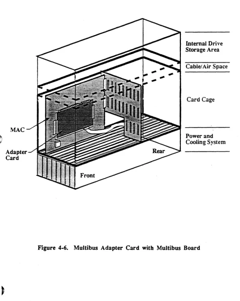
Interface Board RemovaL ... 4-10 Interface Board Installation ... 4- 11 GC/EGC/GC16 Interface Board Setup ... 4-13 GC/EGC DCEJDTE Pon Configuration ... 4-14 GC16 DCE/DTE Pon Configuration ... 4-16 SCSI Interface Board Setup ... 4-18 Single-ended Mode Configuration ... 4-18 Differential Mode Configuration ... 4-18 Multibus Adapter Card Setup ... 4-20 VMEbus Adapter Card Setup ... ; ... 4-22
Preface
Terminals, Printers, And Modems ...•... 5-1
The RS-232C' Standard ... 0 • • • • • • • 5-1. Console Terminal Installation ... 0 ••••••••••• 0.0 ••••• 5-3 CPU32 Remote Diagnostic Console ... 5-5 Multiple TellIlinal Installation ... ,; ... 5-6 Printer Installation ... 5-8 Mcxiems ... 5-9
Subassembly Removal And Installation ...•... 6-1
Internal Drive Storage Area ... 6-2Accessing The Internal Drive Storage Area ... 0 0 •• 0 •• 0 .• 6-2 Reassembly Of The Internal Drive Storage Area ... 0 • • • • 6-3
Cartridge Tape Drive Assembly ... 6-4 Removing a Cartridge Tape Drive ... 0 6-4
Installing a Cartridge Tape Drive ... 0 o • • 6-6
Keyswitch Assembly ... 0 • • • • 0 • • • • • • • • • 6-7
Removing the Keyswitch Assembly ... 6-7 Installing the Keyswitch Assembly ... 6-7 Fan Assembly ... 6-8 Main Fan Assembly ... 6-9 Removing the Main Fan, Assembly ... 6-9 Installing the Main Fan Assembly ... 6-9 Drive Storage Fan Assembly ... 6-10
Removing The Drive Storage Fan Assembly ... 6-10 Installing The Drive Storage Fan Assembly ... 6-10
rf
Disk Drive Assemblies .. : ... 6-11 \~Vertical HSMD/SMD Disk Drives ... 6-12 Removing a Vertical-Mount HSMD/SMD Disk Drive ... 6-12 Installing a Vertical-Mount HSMD/S:MD Disk Drive ... 0 • • • • • • • • 6-14
Venical S CS I Disk Drives ... 6-16 Removing a Vertical-Mount SCSI Disk Drive ... 6-16 Installing a Vertical-Mount SCSI Disk Drive ... 00.6-18 Horizontal SCSI Disk Drives ... 0 ••. 0 .•••.. 0 • 6- 21 Removing a Horizontal-Mount SCSI Disk Drive ... 6-21 Installing a Horizontal-Mount S-CSI Disk Drive ... 6-22 Power Supply Assembly ... 6-25 Removing the Power Supply Assembly ... 6-25 Installing the Power Supply Assembly ... 6-26 Power Supply Voltage Setting ... 6-27
Preface
Peripherals ... . -... " ... . 7·1 Expansion Cabinet ... 7 -2 Cartridge Ta}Je Drives ... 7-4
Archive Viper Cartridge Tape Drives ... 7-4
Wangtek Camidge Tape Drives ... 7-4
9-Track Operation ... 7-6 9-Track Device Numbering Scheme ... 7-6
Cipher 9-Track Operation ... 7-8 Disk Drives ... 7 -1 0
SCSI Optical Disk Drives ... ' ... 7 -10 Fujitsu Disk Drives ... 7-10 SCSI Disk Drives ... 7-11 Modular Communications Processor ... 7 -12 MCP Installation ... 7-12
Preventive Maintenance ... ' ... 8- 1 System Exterior ... 8-1
System Fan Filters ...
8-2
Cartridge TaJ>C Drives ... 8-2
Archive Viper Cartridge Tape Drives ... 8-3
Wangtek Camidge rape Drives ...
8-4
Cipher 9-Track Tape, Drive ... 8 -5
Functional 0 perations ... 9 -1 Bus System ... : ... 9-2
Communications and Control Bus (CCB) ... 9-2 Processor Memory Bus (PMB) ... 9-2
Mass Storage Bus (MSB) ... 9-3 Utility Transfer Bus (UTE) ... 9-3
Backolane ... 9-4
Computarionai Subsystem ... 9-5 Application Processor ... 9-5 Multiple AP Capabilities ... 9-5 Memory Management Unit {MMU) ... 9-6 Cache Memory ... 9-6 Cache Theory ... 9-7 Cache Data Bits ... 9-7 Cache Tag Bits ... 9-7
)
Preface,
Processor I/O 0 0 0 0 0 0 • • • 0 • • • • • • • • • • • • • • • • • • • • • • • • • • • • • • • • • • • • • • • • • • • • • • • • • • • • • • • • • • • • • • • • • • • 9-8
System Console, Pon .... ' ... ' ... ' ... 9~·8
System Status Input Register ... 9-8 Diagnostic LED Display ... : ... 9-9 PROM Monitor ... ~ ... ' ... 9-9 Direct Memory Controller (DMC) ... 0 0 • • 0 0 0 0 . 0 . 0 • • • • • • • • 0 . 0 0 0 • • • • • • • o • • 0 0 ' • • • • 9-9
CCB Interface. 0 0 • • • • • • • • • • • • • • • • • • • • • • • • • • • • • 0 • • • • • • • • 0 • • • • 0 • • • • ~ • • • • • • • • • o • • • • • • • • • • ·9-10
PMB Interface. 0 • • • • • • • • 0 0 0 • • • • 0 o • • • • • • • • • • • • • • • 0 · ' 0 • • • • 0 • • • • • • • • • • • • • • • • • • • • • • • • • • • • • • 9-10 Direct Memory Access Control ... ~ . ~ ... ~ .... 9-11 Memory Refresh Conanl ... 9-11 Error Detection And Correction (EDAC) ... ~.~ ... 9-11 Memory Board ... ; .. ' ... 9-12
Memory Organization And Performance ... " ... 9-12 CCB Interface ... 0 • • • • • • • • • • o • • • • 0 0 • • • 0 . 0 • o • • • • • • • • • • • • 0 • • • • • • • • • • • • • • . • • • • • • • • 9-13
PMB
Interface ... ' ... 9-13 Input/Output Subsystem ... 9-14 Database' Processor (OP) ... ~ ...•... 9-14Communications And Control B us Interface ... o • • • • • • 9-14
Data Bus Control (DBC) ... : ... 9-14
Mass Storage Bus Interface ... ' ... 9-15 Interface Bus (IB) ... ~ ... , ... 9-15
Disk
and TaI'C Drive ... 9-15 Intelligent Communications Processor (ICP) ... 9-16 CCB Interface 0 • 0 0 • 0 • • • • 0 • • • 0 0 0 • • • • • 0 0 • • 0 • • • • • • • • • • • • • • • • • • • • • • • • • • • • • • • • • • • • • • • • • • • • • 9-16Processor And Memory Section ... 9-17 I/O Section ... 9-17 Software Description ... 9-17 ~ Hardware Reliability ... 0 • • • • • • • 0 • • • • • • • • • • • • • • • • • • • • • • • • • • • • • • • 9-17
Tempera.tllIe Monitors ... ' ... 9-17
Technical
Support ...•.•.. ,
...
£-\-1Glossary ... G-l
Preface
Tables
Table 1-1. Base Configuration Summary of Model 825/800 ... 1-2
Table 1-2. ARIX System Power Capacities ... 1-2 Table 1-3. Maximum Cabinet Capacities. . . .. 1-3
Table 4-l.
I/O
Family Related Boards ... 4-3 Table 4-2.DP/ICP
Device Suppon ... 4-3 Table 4-3. OP Logic Board Device S uppon ... 4-3 Table 4-4. Card Cage Slot Assignments ... 4-4 Table 4-5. GC/EGC DCE/DTE Pon Configuration ... 4-14 Table 4-6. GC 16 DCE/DTE Port Configuration ... 4-16Table 5-1. EIA Voltage Definition ... 5-1 Table 5-2. Serial RS-232C And RJ-12 Signal Summary ... 5-2
Table 7-l. 825/800 Expansion Cabinet Maximum Capacities ... 7-1 Table 7-2. 9-Tra_ck Tape Drive Devices ... 7-6 Table 7-3. 9-Track Bit Map ... 7-7
~,
~
Table 7-4. 9- Track Options ... 7-8
Table 9-1. System Status Error Codes ... 9-9
)
Preface
Figure 1-1.
Figure 3-1. Figure 3-2. Figure 3-3. Figure 4-1. Figure 4-2. Figure 4-3. Figure 4-4. Figure 4-5. Figure 4-6. Figure 4-7. Figure 5-1. Figure 6-1. Figure 6-2. Figure 6-3. Figure 6-4. Figure 6-5. Figure 6-6. Figure 6-7. Figure 6-8. Figure 6-9. Figure 6-10. Figure 7-1. Figure 7-2. Figure 7-3. Figure 7-4. Figure 7-5. Figure 8-1. Figure 8-2.
Figures
ARIX Model 825/800 .... ~ ... ~ ... 1-4Rear Panel ... 3- 3 Front Panel ... 3-4 AC Power Connections ... 3-5
Logic and Interface Boards ... 4-2 CPU Master/Slave Switch ... 4-5 GC/EGC Interface Board ... 4-15 GC16 Interface Board ... ~ ... 4-17 SCSI Interface Board ... 4- 19 Multibus Adapter Card with Multibus Board ... 4-21 VMEbus Adapter Card with V~bus Board ... 4-23
Model
825/800,
Rear View ... 5-4 Internal Rear View ... 6-5Internal Front View ... 6- 8 SMD Disk Drive Settings ... 6-13 Vertical-Mount HS:MD/SMD Drives ... 6-15 Vertical-Mount SCSI Drives ... 6-17 CDC 170 Mbyte SCSI Disk Drive Settings ... 6-19 CDC 380 Mbyte SCSI Disk Drive Settings ... 6-20 Horizontal-Mount SCSI Drives ... 6-23 Power Supply, Front View ... 6-28
Power Supply, Rear View ... 6-29
E xpanslon . Cab' lnet ... . . . .. /--... " Expansion Connector Panel ... ' ... 7-3 Archive Viper Tape Drive-(Front View) ... 7-5 Cipher Control Panel ... 7-9 MCP Connections ... 7- 13
Cipher Air Filter Removal ... 8-6 Cipher 9-track Maintenance Locations ... 8-7
)
Section I Introduction
ARIX
825/800
1
Introduction
ARIX systems are high-performance, UNIX multi-application processing computers designed to quickly and reliably handle the high demands of multiple user-intensive applications and throughput~ for commercial applications.
The ARIX models 800 and 825 are functionally identical in bus snucrure and are referred to as the 825/800 throughout t~is manual.
The 825/800 systems suppon up to 10 boards: three rvtEMORY /CPU, one DMA controller (DMC2 or DMC4/2), and six Intelligent Communication Processor (ICP) boards.
The tables and figures in this section describe the ARIX system~ as follows:
• Table 1-1 is a base configuration summary of the models 825/800
• Table 1-2.shows the system power capacities.
• Table 1-3 shows the maximum main cabinet capacities of the 825/800 systems.
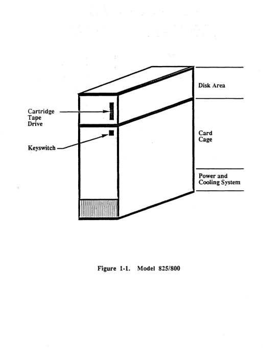
• Figure 1-1 is a front view of the model 825/800; notice the tape" cartridge.
Expansion Cabinets are used to house additional disk, cartridge, and/or 9-track tape drive devices and are added to the system to extend the peripheral device suppon capacity.
I nrroduction
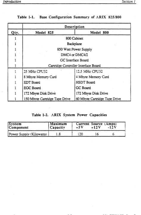
Table 1·1. Base Configuration Summary of ARIX 825/800
Description
.
Qty. Model 825 Model 800
1 800 Cabinet
1 Backplane
1 850 Watt Power Supply
1 DMC4 or DMC4/2
1 GC Interface Board
1 Cartridge Controller Interface Board
1 25 MHzCPU32 12.5 MHz CPU32
1 8 Mbyte Memory Card 4 Mbyte Memory Card
1 EDT Board HSDTBoard
1 EGCBoard GC Board
1 172 Mbyte Disk Drive 172 Mbyte Disk Drive
1 150 Mbvte Cartridge Tape Drive 60 Mbvte Cartridge Tape Drive
Table 1·2. ARIX System Power Capacities
!System Component
MaXimum Capacity
Current Source {Amps)
+5V +12V -12V
Power Suooiv (Kilowatts)
I
1.8 120 16 6Section 1
I
II
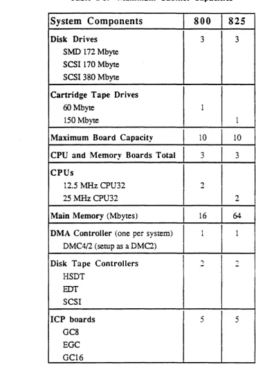
[image:52.617.93.567.34.759.2]Section I I nrroduction
Table 1-3. Maximum Cabinet Capacities
System Components
800
825
Disk Drives
3 3SMD 172 Mbyte SCSI 170 Mbyte SCSI 380 Mbyte
Cartridge Tape Drives
60 Mbyte 1
150 Mbyte 1
Maximum Board Capacity
10 10CPU and Memory Boards Total
3 3CPUs
12.5 ?v1Hz CPU32 2
25 MHzCPU32 2
Main Memory
(Mbytes) 16 64DMA Controller
(one per system) 1 1 DMC4/2 (setup as a DMC2)Disk Tape Controllers
2 ~...
,HSDT
EDT
SCSIICP boards
5 5GC8 EGC GC16
)
[image:53.615.67.438.95.639.2]I ntroducrion
Cartridge Tape Drive
Keyswitch
•
Figure 1-1. Model 8251800
Disk Area
C