HOW to DESIGN, BUILD
and TEST SMALL
LIQUID-FUEL
ROCKET ENGINES
NOTICE
ROCKETLAB cannot assume responsibility, in any manner whatsoever, for the use readers make of the information
presented herein or the devices resulting therefrom.
CORRESPONDENCE
Comments regarding this booklet should be sent to:
Note: The following address has not been verified and may not be current, since it was the address listed in the original text from 1967.
ROCKETLAB
Post Office Box 1139 Florence, Oregon 97439
COVER PHOTOGRAPH
Exhaust plume from small 75-lb thrust water cooled liquid-fuel rocket engine. Propellants are gaseous oxygen and methyl alcohol. Official U. S. Navy photograph.
Note: Photograph mentioned was not included in this PDF version due to it’s poor quality (my copy of the book is pretty ragged) and it appears to be the quality of a Xerox copy to start.
Copyright „ 1967 by Leroy J. Krzycki Printed in the United States of America First printing: March 1967
Second printing: March 1971 ISBN 9600-1980-4
HOW to DESIGN, BUILD and TEST
SMALL LIQUID-FUEL ROCKET ENGINES
CONTENTS
5 INTRODUCTION
7 PROPELLANT CHOICE
12 PROPELLANT PROPERTIES 13 DESIGN EQUATIONS
13 Nozzle
17 Combustion Chamber
18 Chamber Wall Thickness
19 Engine Cooling
20 Heat Transfer
21 Materials
23 Injectors
26 EXAMPLE DESIGN CALCULATION
33 Design
34 FABRICATION
39 TESTING EQUIPMENT
39 Feed System
39 Feed System Components
48 TEST STAND
51 SAFETY EQUIPMENT
53 ENGINE CHECK-OUT AND CALIBRATION 55 IGNITION AND OPERATION
60 THE LAW
61 BIBLIOGRAPHY 63 LIST OF SUPPLIERS 70 CONVERSION FACTORS
FOREWORD
The rocket engine is a relatively simple device in which the propellants are burned and the resulting high pressure gases are expanded through a specially shaped nozzle to produce thrust. Gas pressurized propellant tanks and simple propellant flow controls make operation of a small liquid-fuel rocket engine about as simple as operating an automobile engine. When then do so many amateur rocket engines fail or cause injury? The reason, usually and simply, is that the amateur is not accustomed to high pressure devices operating near material temperature limits. His normal every day life is, instead, filled with devices and gadgets operating at low pressures and at low thermal energy levels. With proper design, careful workmanship, and good test equipment operating in a safe manner, the amateur can build small liquid-fuel rocket engines which will have hours of safe operating life.
HOW to DESIGN, BUILD and TEST
SMALL LIQUID-FUEL ROCKTET ENGINES
INTRODUCTION
A liquid rocket engine employs liquid propellants which are fed under pressure from tanks into a combustion chamber. The propellants usually consist of a liquid oxidizer and a liquid fuel. In the combustion chamber the propellants chemically react (burn) to form hot gases which are then accelerated and ejected at high velocity through a nozzle, thereby imparting momentum to the engine. Momentum is the product of mass and velocity. The thrust force of a rocket motor is the reaction experienced by the motor structure due to the ejection of the high velocity matter. This is the same phenomenon which pushes a garden hose backward as water squirts from the nozzle or makes a gun recoil when fired.
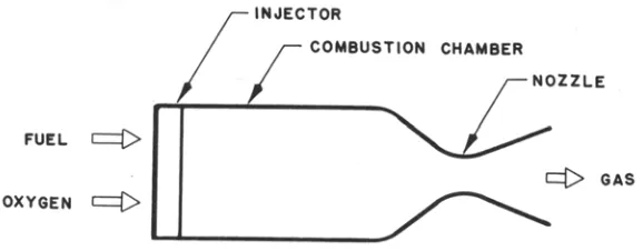
[image:5.612.162.451.554.667.2]A typical rocket motor consists of the combustion chamber, the nozzle, and the injector, as shown in Figure 1. The combustion chamber is where the burning of propellants takes place at high pressure.
The chamber must be strong enough to contain the high pressure generated by, and the high temperature resulting from, the combustion process. Because of the high temperature and heat transfer, the chamber and nozzle are usually cooled. The chamber must also be of sufficient length to ensure complete combustion before the gases enter the nozzle.
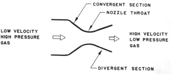
[image:6.612.168.450.524.650.2]The function of the nozzle is to convert the chemical-thermal energy generated in the combustion chamber into kinetic energy. The nozzle converts the slow moving, high pressure, high temperature gas in the combustion chamber into high velocity gas of lower pressure and temperature. Since thrust is the product of mass (the amount of gas flowing through the nozzle) and velocity, a very high gas velocity is desirable. Gas velocities from on to two miles per second (5,000 to 12,000 feet per second) can be obtained in rocket nozzles. Nozzles which perform this seemingly amazing feat are called DeLaval nozzles (after their inventor) and consist of a convergent and divergent section, as shown in Figure 2. The minimum flow area between the convergent and divergent section is called the nozzle throat.
The flow area at the end of the divergent section is called the nozzle exit area. The nozzle is usually made long enough (or the exit area is great enough) such that the pressure in the combustion chamber is reduced at the nozzle exit to the pressure existing outside the nozzle. If the rocket engine is being fired at sea level this pressure is about 14.7 pounds per square inch (psi). If the engine is designed for operation at high altitude the exit pressure is less than 14.7 psi. The drop in temperature of the combustion gases flowing through the nozzle is high and can be as much as 2,000° – 3,000° F. Since the gases
in the combustion chamber may be at 5,000° – 6,000° F, the gas
temperature at the nozzle exit is still about 3,000° F.
PROPELLANT CHOICE
Liquid rocket engines can burn a variety of oxidizer and fuel combinations, some of which are tabulated in Table I. Most of the propellant combinations listed are dangerous, toxic, and expensive. The amateur builder of rocket engines on the other hand, requires propellants that are readily available, reasonably safe and easy to handle, and inexpensive. Based on experience, ROCKETLAB recommends the use of gaseous oxygen as the oxidizer and a hydrocarbon liquid as the fuel. They give good performance, the combustion flame is readily visible, and their combustion temperature presents an adequate design challenge to the amateur builder. The propellants are used in the Atlas missile and the Saturn space booster. In these systems, however, liquid rather than gaseous oxygen is used as the oxidizer.
Hydrocarbon fuels, such as gasoline and alcohol, are readily available in any community. Safety precautions are already known by most responsible individuals due to wide use of the fuels in internal combustion engines for automobiles and power equipment.
All subsequent sections of this publication will refer to, and assume, that the propellants to be used in amateur liquid-fuel rocket engines are gaseous oxygen and hydrocarbon fuel.
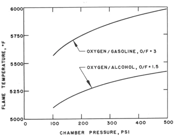
Figure 3 Flame temperature versus chamber pressure at stoichiometric mixture ratio
When a stoichiometric ratio is achieved just enough oxygen is present to chemically react with all of the fuel; the highest flame temperature is achieved under these conditions. If a lower flame temperature is desired it is usually better to have more fuel present than oxidizer; this is known as burning “off-ratio” or “fuel rich.” This condition is less severe on the rocket engine than burning at stoichiometric oxygen-rich conditions.
Figure 4 Flame temperature versus mixture ratio at a constant chamber pressure of 300 psi
The thrust developed per pound of total propellant burned per second is known as specific impulse and is defined as:
Figure 5 Isp performance of hydrocarbon fuels with gaseous
oxygen.
Since the minimum Isp mixture ratio (r) for oxygen and gasoline
PROPELLANT PROPERTIES
DESIGN EQUATIONS
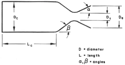
[image:13.612.187.426.184.309.2]The following section will detail simplified equations for the design of small liquid-fuel rocket motors. The nomenclature for the motor design is shown in Figure 6.
Figure 6 Motor Design Configuration
Nozzle
The nozzle throat cross-sectional area may be computed if the total propellant flow rate is known and the propellants and operating conditions have been chosen. Assuming perfect gas law theory:
where R = gas constant, given by R = R / M. R is the universal gas constant equal to 1545.32 ft-lb/lb° R, and M is the molecular
weight of the gas. The molecular weight of the hot gaseous products of combustion of gaseous oxygen and hydrocarbon fuel is about 24, so that R is about 65 ft-lb/lb° R.
gc is a constant relating to the earth’s gravitation and is
equal to 32.2 ft/sec/sec.
For further calculations the reader may consider the following as constants whenever gaseous oxygen and hydrocarbon fuel propellants are used:
Tt is the temperature of the gases at the nozzle throat. The
gas temperature at the nozzle throat is less than in the combustion chamber due to loss of thermal energy in accelerating the gas to local speed of sound (Mach number = 1) at the throat. Therefore
Tc is the combustion chamber flame temperature in degrees
Pt is gas pressure at the nozzle throat. The pressure at the
nozzle throat is less than in the combustion chamber due to acceleration of the gas to the local speed of sound (Mach number =1) at the throat. Therefore
The hot gases must now be expanded in the diverging section of the nozzle to obtain maximum thrust. The pressure of these gases will decrease as energy is used to accelerate the gas and we must now find that area of the nozzle where the gas pressure is equal to atmospheric pressure. This area will then be the nozzle exit area.
Mach number is the ratio of the gas velocity to the local speed of sound. The mach number at the nozzle exit is given by a perfect gas law expansion expression
Pc is the pressure in the combustion chamber and Patm is
The nozzle exit area corresponding to the exit Mach number resulting from the choice of chamber pressure is given by
Since g is fixed at 1.2 for gaseous oxygen and hydrocarbon propellant products, we can eliminate the parameters for future design use; the results are tabulated in Table III.
Therefore,
The temperature ratio between the chamber gases and those at the nozzle exit is given by
and the exit diameter is given by
A good value for the nozzle convergence half-angle b (see Figure 3) is 60°. The nozzle divergence half-angle, a, should be no
greater than 15° to prevent nozzle internal flow losses.
Combustion Chamber
A parameter describing the chamber volume required for complete combustion is the characteristic chamber length, L*,
which is given by
Where Vc is the chamber volume (including the converging
section of the nozzle), in cubic inches, and At is the nozzle throat
area (in2). For gaseous oxygen/hydrocarbon fuels, an L* of 50 to
100 inches is appropriate. L* is really a substitute for
determining the chamber residence time of the reacting propellants.
To reduce losses due to flow velocity of gases within the chamber, the combustion chamber cross-sectional area should be at least three time the nozzle throat area.
The combustion chamber cross-sectional area is given by
For small combustion chambers the convergent volume is about 1/10 the volume of the cylindrical portion of the chamber, so that
The chamber diameter for small combustion chambers (thrust levels less than 75 pounds) should be three to five times the nozzle throat diameter so the injector will have useable face area.
Chamber Wall Thickness
The combustion chamber must be able to withstand the internal pressure of the hot combustion gases. The combustion chamber must also be physically attached to the cooling jacket and, therefore, the chamber wall thickness must be sufficient for welding or brazing purposes. Since the chamber will be a cylindrical shell, the working stress in the wall is given by
Where P is the pressure in the combustion chamber (neglecting the effect of coolant pressure on the outside of the shell), D is the mean diameter of the cylinder, and tw is the thickness of the
cylinder wall. A typical material for small water-cooled combustion chambers is copper, for which the allowable working stress is about 8,000 psi. The thickness of the combustion chamber wall is therefore given by
Equation (22) can also be used to calculate the wall thickness of the water cooling jacket. Here again, the value of tw
will be the minimum thickness since welding factors and design considerations (such as O-ring grooves, etc.) will usually require walls thicker than those indication by the stress equation. A new allowable stress value must be used in Equation (22), dependent on the jacket material chosen.
Engine Cooling
The amateur should not consider building un-cooled rocket engines since they can operate for only a short time and their design requires a thorough knowledge of heat and mass transfer engineering. Cooled rocket motors have provision for cooling some or all metal parts coming into contact with the hot combustion gases. The injector is usually self-cooled by the incoming flow of propellants. The combustion chamber and nozzle definitely require cooling.
A cooling jacket permits the circulation of a coolant, which, in the case of flight engines is usually one of the propellants. However, for static tests and for amateur operation, water is the only coolant recommended. The cooling jacket consists of an inner and outer wall. The combustion chamber forms the inner wall and another concentric but larger cylinder provides the outer wall. The space between the walls serves as the coolant passage. The nozzle throat region usually has the highest heat transfer intensity and is, therefore, the most difficult to cool.
1. Use water as the coolant.
2. Use copper for the combustion chamber and nozzle walls.
3. Water flow velocity in the cooling jacket should be 20 to 50 feet per second.
4. Water flow rate should be high enough so that boiling does not occur.
5. Extend the water cooling jacket beyond the face of the injector.
6. A steady flow of cooling water is essential.
Heat Transfer
In water-cooled chambers the transferred heat is absorbed by the water. The water must have an adequate heat capacity to prevent boiling of the water at any point in the cooling jacket. The total heat transferred from the chamber to the cooling water is given by
where
Q = total heat transferred, Btu/sec
q = average heat transfer rate of chamber, Btu/in2-sec
A = heat transfer area, in2
ww = coolant flow rate, lb/sec
cp = specific heat of coolant, Btu/lb°F
T = temperature of coolant leaving jacket, °F
Ti = temperature of coolant entering jacket, °F
The use of this equation will be illustrated in the section Example Design Calculation.
Materials
Once the wall material of an operating rocket engine begins to fail, final burn-through and engine destruction are extremely rapid. Even a small pinhole in the chamber wall will almost immediately (within one second) open into a large hole because of the hot chamber gases (4000-6000°F) will oxidize or
melt the adjacent metal, which is then blown away exposing new metal to the hot gases.
Exotic metals and difficult fabrication techniques are used in today’s space and missile rocket engines, providing a lightweight structure absolutely required for efficient launch and flight vehicles. These are advanced metals and fabrication techniques are far outside the reach of the serious amateur builder. However, the use of more commonplace (and much less expensive!) metals and fabrication techniques is quite possible, except that a flight weight engine will not result. Since almost all amateur rocket firing should be conducted on a static test stand, this is not a severe restriction to the amateur builder. Experience with a wide variety of rocket engine designs leads to the following recommendations for amateur rocket engines:
1. The combustion chamber and nozzle should be machined in one piece, from copper.
2. Those injector parts in contact with the hot chamber gases should also be machined from copper.
3. The cooling jacket and those injector parts not in contact with the hot propellant gases, should be fabricated from brass or stainless steel.
Injectors
The function of the injector is to introduce the propellants into the combustion chamber in such a way that efficient combustion can occur. There are two types of injectors which the amateur builder can consider for small engine design. One of these is the impinging stream injector in which the oxidizer and fuel are injected through a number of separate holes so that the resulting streams intersect with each other. The fuel stream will impinge with the oxidizer stream and both will break up into small droplets. When gaseous oxygen is used as the oxidizer, and a liquid hydrocarbon is used as the fuel, the impingement of the liquid stream with the high velocity gas stream results in diffusion and vaporization, causing good mixing and efficient combustion. A disadvantage of this type of injector is that extremely small holes are required for small engine flow rates and the hydraulic characteristics and equations normally used to predict injector parameters do not give good results for small orifices. The small holes are also difficult to drill, especially in soft copper.
However, to provide a complete picture of the equations used in rocket engine design, we present below the equation for the low of liquid through a simple orifice (a round drilled hole, for example)
where
w = propellant flow rate, lb/sec A = area of orifice, ft2
DP = pressure drop across orifice, lb/ft2 r = density of propellant, lb/ft3
g = gravitational constant, 32.2 ft/sec2
The discharge coefficient for a well-shaped simple orifice will usually have a value between 0.5 and 0.7.
The injection velocity, or velocity of the liquid stream issuing from the orifice, is given by
Injection pressure drops of 70 to 150 psi, or injection velocities of 50 to 100 ft/sec, are usually used in small liquid-fuel rocket engines. The injection pressure drop must be high enough to eliminate combustion instability inside the combustion chamber but must not be so high that the tankage and pressurization system used to supply fuel to the engine is penalized.
The use of commercial spray nozzles for amateur-built rocket engines is highly recommended.
EXAMPLE DESIGN CALCULATION
The following example illustrates the use of the equations, tables, and concepts presented in the previous sections.
A small water-cooled liquid-fuel rocket engine is to be designed for a chamber pressure of 300 psi and a thrust of 20 pounds. The engine is to operate at sea level using gaseous oxygen and gasoline propellants.
Step 1
From Table I and Figures 3, 4, and 5 we determine that the optimum O/F ratio is about 2.5 and that the ideal specific impulse will be about 260 seconds. The total propellant flow rate is given by Equation (3)
Since the mixture ratio, r, is 2.5, we find from Equation (5)
From Equation (6) the oxygen flow rate is
Step 2
From Table I we note that the chamber gas temperature is 5 7 4 2°F, or about 6202°R. From Equation (9) the gas
temperature at the nozzle throat is
Step 3
From Equation (12) the pressure at the nozzle throat is
Step 4
The nozzle throat area is given by Equation (7)
Step 5
The nozzle throat diameter is given by Equation (17)
Step 6
so that the nozzle exit area is, from Equation (15)
Step 7
The nozzle exit diameter is, from Equation (17)
Step 8
For this propellant combination we will assume a combustion chamber L* of 60 inches. The combustion chamber
volume is given by Equation (19)
Step 9
The chamber length is found from Equation (21)
However, we must first determine the chamber area, or Ac. We
do this by assuming that the chamber diameter is five times the nozzle throat diameter or Dc = 5Dt, therefore
Step 10
Copper will be used for the combustion chamber and nozzle wall. The chamber wall thickness is given by Equation (23)
To allow for additional stress and welding factors we shall set the wall thickness equal to 3/32 or 0.09375 inch and will assume that the nozzle wall has this thickness also.
Step 11
Previous experience with small water-cooled rocket engines has shown that we can expect the copper combustion chamber and nozzle to experience an average heat transfer rate, q, of about 3 Btu/in2-sec. The heat transfer area of the
combustion chamber is the outer surface area of the chamber and nozzle. The surface area is given by
The area of the nozzle cone up to the throat can be assumed to be about 10% of the chamber surface area so that
Step 12
The cooling water flow rate can be calculated by assuming a desired temperature rise of the water. If this is 40°F then,
from Equation (24)
Step 13
The annular flow passage between the combustion chamber wall and the outer jacket must be sized so that the flow velocity of the cooling water is at least 30 ft/sec. This velocity is obtained when the flow passage has dimensions as determined below:
where vw = 30 ft/sec, ww = 0.775 lb/sec, r = 62.4 lb/ft3, and A is
the area of the annular flow passage, given by
where D2 is the inner diameter of the outer jacket and D1 is the
outer diameter of the combustion chamber, given by
The water flow gap is 0.0425 inch.
Step 14
The fuel injector for this small rocket engine will be a commercial spray nozzle with a 75° spray angle. The required
capacity of the nozzle is determined by the fuel flow rate
Since there are six pounds of gasoline per gallon, the spray nozzle flow requirement is 0.22 gallons per minute (gpm). The spray nozzle can now be ordered from any of several suppliers (see List of Suppliers); nozzle material should be brass to ensure adequate injector heat transfer to the incoming propellant.
If an impinging jet injector had been chosen, the determination of the required injector hole number and size would have been as follows:
The flow area for fuel injection is given by Equation (25)
We will assume that Cd = 0.7 with a fuel injection pressure drop
If only one injection hole is used (a poor practice which can lead to combustion instability) its diameter would be
A number 69 drill could be used for this hole.
If two fuel injection holes are used, their diameter would be
A number 75 drill could be used for these holes.
Step 15
The injection holes for the gaseous oxygen will be simple drilled orifices. The size of these orifices should be such that a gas stream velocity of about 200 ft/sec is obtained at design oxygen flow rate. The holes must not be so small that sonic velocity is achieved in the orifice passages since this would result in a high upstream pressure requirement to drive the required amount of oxygen through the orifices.
Assuming incompressibility, the injection flow area is given by
Since we know the oxygen flow rate and the desired injection velocity, we can easily find the total injection area
Since there are to be four holes, each hole has an area of 0.004375 in2 and the diameter of each hole is
A number 48 drill could be used for these holes.
These same size oxygen jets could also be used with two fuel jets in the impinging stream injector. The holes, oxygen and fuels, should be drilled at an angle of 45° with respect to the
injector face with the intersection point of the streams about 1/4 inch inside the combustion chamber.
Design
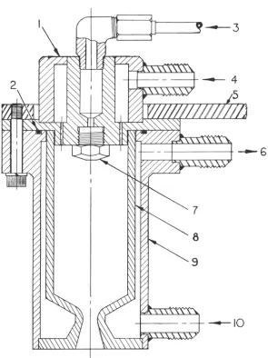
Using the dimensions obtained in the example calculation, and the design technique described above, the rocket engine assembly design shown in Figure 8 is obtained. The engine design features easy fabrication and assembly.
FABRICATION
The fabrication and assembly of a small liquid fuel rocket engine is no more difficult than the more serious amateur machine projects, such as model steam engines, gasoline engines, and turbines. Because the rocket engine has no rotating parts, dynamic balance of components is not required. However, the use of quality, homogeneous materials and careful fabrication technique are definitely required to produce a safe, working, rocket engine.
A properly designed small liquid-fuel rocket engine requires the following machine and hand tools:
1. 6” or 10” metal-turning lathe, with attachments
2. Precision drill press
3. hand files, calipers, micrometers, etc.
4. oxy-acetylene torch or small arc welder.
Since a properly designed engine will have symmetrical parts, a milling machine or planer will not be required. The metal-turning lathe should have a repeatable accuracy of 0.001 inch. The drill press will be used to drill small diameter holes and should have a true running, high speed chuck.
The joining of the various engine components is especially critical since the engine will operate at high pressure and high temperature.
Figure 8 Assembly drawing of small liquid-fuel rocket engine.
(1) injector assembly (6) coolant
(2) O-ring (7) fuel spray nozzle
(3) liquid fuel (8) combustion chamber
(4) gaseous oxygen (9) outer shell
The ability of the welder, and the welding techniques employed, should be as good as those required for aircraft work. Metal joints must be clean, with a close fit between parts to ensure adequate weld strength and integrity. To the extent possible, assembled components should be pressure tested with water (or nitrogen gas, but that is dangerous) prior to actual use with propellants. Repair of leaks or initially poor welds must be carefully done with subsequent retesting with pressurized water (called hydro-testing or hydrostatic testing).
As discussed previously, the combustion chamber and nozzle should be built as a one piece unit. This arrangement, while more difficult from a machining point of view, eliminates the requirement for a joint of some kind between the two parts; this joint would be exposed to the hot combustion gases (5700°F) on one side and would, in all probability, fail. Building
the combustion chamber and nozzle in one piece eliminates this potential failure point. Care must be exercised during the machining of the copper chamber-nozzle to ensure constant wall thickness and the correct taper in the nozzle region. Thin wall sections are potential failure points and could result in almost immediate catastrophic failure during firing.
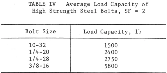
pounds) but, rather, the pressure forces attempting to separate the injector from the shell. The pressure acting on the injector area out to the point of sealing between the injector and the outer shell is the combustion chamber pressure, which is typically 100 to 300 psi. The force attempting to separate the injector from the shell is slightly over 600 pounds for the design shown in Figure 8 at a combustion pressure of 300 psi. The bolts holding the two components together (and in this case also holding the assembly to the test mount) must withstand this force with an adequate safety factor (typically a factor of two). The number and size of bolts required can be obtained from Table IV, which gives the average load capacity of high strength steel bolts of various sizes. The strength of these bolts, however, depends to some extent on the adequacy of the threads in tapped holes, the tapped material, and the bolt tightening procedure used in assembly.
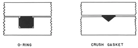
The outer shell must also contain a sealing device to prevent the high pressure combustion chamber gas from flowing back past the injector. Which an appropriately configured water-cooled design, the use of an elastomeric O-ring is highly desirable. A standard neoprene O-ring (manufactured by a number of companies, see List of Suppliers) will give reliable service if the surrounding metal does not exceed a temperature of 200-300°F. Dimensions and design parameters
Another method of sealing is the use of an asbestos-copper crush gasket (very similar to those used on automobile spark plugs, only larger; see List of Suppliers). The copper crush gasket in positioned by a V-groove cut in the surface of the outer jacket at the sealing point. The mating surface of the injector should be smooth and flat, with no machine marks.
Figure 9 illustrates the relationship between an O-ring and a copper crush gasket and their mating surfaces.
Figure 9 Detail on ring and crush gasket sealing methods. O-ring groove dimensions are critical and should be obtained from suppliers handbooks. Crush gasket groove dimensions are non-critical; groove depth should be about 1/3 the thickness of uncrushed gasket.
The injector should be fabricated from copper to provide maximum heat transfer from the injector face to the incoming propellants. The outer shell of the injector can be made from either copper, stainless steel, or brass. However, since the propellant inlet fittings (again these should be the tapered seat, metal-to-metal kind) should be stainless steel for best results. It is usually a good idea to make the injector outer shell from stainless steel so that the inlet fittings can be attached to the remainder of the injector by silver brazing without weakening the inlet fitting welds.
important that injector components be thoroughly cleaned and de-burred prior to assembly. After injector welding, hot water should be used to thoroughly clean the injector assembly of brazing flux and residues, and the assembly should receive a final rinse in acetone or alcohol.
TESTING EQUIPMENT
In this section we shall discuss the auxiliary equipment needed to operate the rocket engine, the installation of this equipment, and its safe use in engine operation.
Feed System
The feed system for amateur rocket engine testing consists of a tank to store the liquid fuel, a regulated supply of high pressure nitrogen gas to force the fuel from the tank into the engine, a regulated supply of high pressure gaseous oxygen, and a control device for regulating the propellant flow rates. A typical pressurized feed system is shown schematically in Figure 10.
Feed System Components
High Pressure Gas Cylinders
Figure 10 Schematic diagram of gas pressure feed system. Propellants are a liquid fuel and gaseous oxygen. (1) high pressure gaseous nitrogen supply, (2) pressure regulator, (3) check valve, (4) fuel tank, (5) gaseous oxygen cylinders, (6) relief valve, (7) vent valve, (8) fill port, (9) drain valve, (10) remotely operated propellant control valve, (11) fuel filter, (12) purge valve, (13) rocket engine. P is pressure gauge.
Gaseous Nitrogen
[image:41.612.187.434.68.419.2]Gaseous Oxygen
Oxygen will not itself burn but does vigorously support the rapid combustion of almost all other materials. The amateur must be concerned not only with suitability of components for high pressure service but also must use only components that are made from oxygen compatible materials and that are cleaned for oxygen service. All items, including lines, fittings, valves, regulators, etc., MUST be absolutely free from oil, grease, and similar contaminants. Thorough cleaning of all items in solvent, followed by a complete rinse in acetone, is an absolute must. Orders for commercial items should he marked to indicate their intended use with high pressure gaseous oxygen. Many commercial suppliers of valves and regulators offer a special service for cleaning their products for oxygen service. The amateur should avail himself of these services whenever possible, even though they will add slightly to the initial cost of the component.
When cleaning components with solvent or acetone, the amateur builder should observe all rules of safety applying to these chemicals. They are toxic and easily ignited. Cleaning should be done outside and away from buildings, fires, or other possible ignition sources. These fluids should not be stored indoors but in vented lockers away from main buildings.
Fuel Tank
The amateur may build (or have built) a tank especially for his requirements. Seamless tubing or pipe (mild steel or stainless steel) with welded flat end plates makes an excellent tank. Outlet ports are easily tapped in the flat end plates, The tank wall thickness is given by Equation (22)
where P is the pressure in the tank (1 1/2 times the desired operating pressure), D is the outside diameter of the tank, tw is
the wall thickness, and S is the allowable stress. The size of the tank is determined by the size of the rocket engine and the desired operating time. The engine discussed in Example Design Calculation had a fuel flow rate of 0.022 lb/sec. A tank with a 4-inch inside diameter and 12 4-inches long would hold enough gasoline to run this engine for 175 seconds. If the tank outside diameter is 4.5 inches, the allowable stress in the steel is 20,000 psi, and the operating pressure is 500 psi so that the design pressure is 750 psi, a tank minimum wall thickness of 0.085 inch is calculated. A wall thickness of 0.250 inch is chosen to allow for welding factors, stress concentrations, and the size of available seamless tubing. The tank inside diameter is 4.0 inches. The flat end plates for this tank should be at least twice the thickness of the tank wall (i.e. for this case, at least 1/2 inch thick). Drilling and tapping should be done prior to welding, to prevent oil and metal chips from falling into the tank. Welding should be done by an expert with several passes for each end plate (see Figure 11). End plate ports should then be re-tapped. The tank should be thoroughly cleaned and hydrostatically tested prior to use in the rocket engine feed system.
Figure 11 Fuel tank end detail. Several weld passes should be used to attach the end plates to the seamless tubing.
Tanks made from seamless tubing should not be greater than six inches in diameter; wall stress is a function of diameter, and at high stress, specialized design information, not usually available to the amateur builder, is required. Also, the force on the tank end plates increases rapidly with tank diameter.
Gaseous Nitrogen Regulator
Especially attractive is the Grove Mity-Mite regulator with internal regulation. Inexpensive, special fittings are required to attach these regulators to the gas cylinder. These fittings are available from several sources (see List of Suppliers).
Gaseous Oxygen Regulator
The discussion of regulators for gaseous nitrogen service applies to gaseous oxygen also, except that the regulator should be especially cleaned for oxygen service and, if possible, metal-to-metal seats should be used within the regulator. Regulator manufacturers should be consulted for recommendations on seat materials for use with gaseous oxygen in their regulators. Special fittings for attaching the regulator to the oxygen cylinder are available from the sources supplying nitrogen cylinder fittings. These sources can also supply cylinder manifold kits so that two or more oxygen cylinders can be used simultaneously to achieve long engine run durations.
Propellant Control Valves
Other Valves
Other valves required in the feed system include the fuel tank vent and fill valve, the drain valve, and the nitrogen purge valve. Inexpensive, high quality ball valves are highly recommended for these functions since they offer positive shut-off, easy operation with handle indication of on or shut-off, and full line opening. Brass or stainless steel valve bodies with Teflon seats are acceptable, and the valves may be line or panel mounted (see List of Suppliers).
Check Valves
Check valves permit fluid flow in one direction only. They are widely used in the aircraft and hydraulic industry and are manufactured by many companies. l/4-inch line size is recommended for all functions shown in Figure 10 with the exception Of the gaseous oxygen line check valve which should feature metal-to-metal seats and be at least 3/8inch line size. Check valves should be thoroughly cleaned prior to use and tested to insure that the check is working properly.
Relief Valves
The fuel tank requires a relief device of some type to prevent tank failure in the event of over-pressurization. While this is high unlikely, it could happen if the gaseous nitrogen regulator failed to function or shut-off properly. An adjustable spring-loaded relief valve is recommended because it may be set to different pressures as feed system uses change, and because, if used, does not have to be replaced. An alternate device is the burst disc which ruptures at a preset pressure and relieves the overpressure in the tank. Burst discs require replacement after actuation and are not pressure adjustable. A different disc must be used for each pressure range desired.
Fuel Filter
system. A fuel filter which can filter out particles down to ten microns in size is highly recommended and will save the amateur builder much grief when actual testing is started. Several concerns make small filters suitable for rocket engine feed systems (see List of Suppliers).
Pressure Gauges
Fuel, oxygen, water, and combustion chamber pressure are essential measurements for rocket engine operation. Buordon-tube pressure gauges offer accuracy, ruggedness, low cost, and availability for this requirement. Numerous manufacturers make these gauges in a bewildering variety of styles, sizes, and prices. Bronze Bourdon tubes are recommended since they are fully compatible (when cleaned) with gaseous oxygen or hydrocarbon fuel and are so widely used that significant cost savings are possible.
Small (2 1/2 or 3-inch diameter) high pressure gauges similar to those used on oxygen welding regulators should be used by the amateur builder for measuring pressure in the high pressure gas cylinders or manifolds. These gauges can be obtained from a welding supply shop.
Gauges for fuel, oxygen, water, and combustion chamber pressure should be at least 3 1/2 inch diameter for easy reading, from a distance. These 3 1/2 Acaloy gauges of Helicoid (see List of Suppliers) are recommended because of their reliability and low cost. These gauges are easily panel mounted and make a neat test stand installation.
Plumbing
fuel, oxygen, and nitrogen supply system but is not as desirable as stainless steel and is more easily flared. The amateur builder should use only good flaring tools and should form or bend tubing only with a tube bender. Where the fittings screw into fuel tank, valve, or other components having pipe threads, the use of Teflon tape on the threads is recommended. No other pipe thread compound should be used, especially on gaseous oxygen components.
TEST STAND
The amateur rocket engine test stand is a structure which incorporates a method for firmly mounting the rocket engine (preferably in a nozzle-down attitude), a mounting for the propellant flow control needle valves, the fuel tank and associated plumbing, and the oxygen and nitrogen cylinders with regulators and associated plumbing. The operator's station, which is really a part of the test stand, should be physically separated from the test stand proper by at least 20 feet, with a shrapnel barricade between. The operator's station should contain the control valve extensions, the ignition system battery and associated switches, and a mirror system so that the operator does not directly view the operating rocket engine.
The greatest hazard in testing small rocket engines is from shrapnel in the event of engine explosion or disintegration. Therefore, the test stand proper should be suitably barricaded to reduce shrapnel effect in all directions.
(one nitrogen and two oxygen) are mounted at the rear of the test stand and are separated from the control valves compartment by another barricade made from one-inch thick plywood. The nitrogen and oxygen regulators are mounted on this plywood barricade above the cylinders. In this manner, expended cylinders may he replaced with charged cylinders without disturbing the regulators or plumbing. A formed piece of stainless steel tubing between the oxygen manifold and the oxygen regulator and a similar piece of tubing between the nitrogen cylinder and its regulator are removed during cylinder exchange, and then reconnected. Lines should always be capped when not in use to prevent entry of dirt and other foreign objects.
The fuel tank is mounted between the forward steel barricade and the rear plywood barricade on a metal cross-piece attached to both barricades. The tank is mounted in the vertical position with the liquid outlet at the bottom.
Figure 12 Test stand for a small liquid-fuel rocket engine.
cooling water can be observed by the operator as an indication that cooling water is actually flowing through the engine.
The test stand proper should have a framework made from welded or bolted steel angle. The forward steel and rear plywood barricade are bolted to this angle framework providing rigidity and strength. Thee test stand should be firmly attached to the surface of the test area either by bolting to a concrete pad or by weighing down with sand bags or concrete weights.
SAFETY
Because of the physical hazards involved in handling propellants and controlling high pressure combustion proeesses, certain elementary safety precautions must be observed in static testing of rocket engines. During the design, and later, the operation of amateur liquid rocket engines, the following general safety precautions shou1d be observed:
1. The operator should be protected by a suitable
barricade located some distance (at least 20 feet) from the test unit.
2. Control of valves during engine ignition and steady-state operation should be by remote means, which for amateur units is best achieved by manual control of needle valves via valve stem extensions.
3. A large chemical fire extinguisher (or, at least, a plentiful supply of water) should always be on hand.
5. Separating of fuel and oxidizer storage reduces the fire and explosion hazard and limits the amount of
propellant stowed in any one area.
6. The test stand unit should be barricaded on several sides to reduce shrapnel effect in event of explosion.
7. Valves, pressure gauges, and other components which directly sense fluid properties should not be located in the operator's station, but should be on the test stand and remotely read. This rule does not apply to electrical instrumentation wherein a transducer is located on the test stand and an electrical readout (such as a meter) is located at the operator's station (this type of
instrumentation is very expensive and is beyond the reach of most amateurs).
8. Warning signals should be given prior to tests (or whenever gas cylinder valves are open) to notify personnel that the area is hazardous. A test must NEVER be conducted until the operator has assured himself that all personnel are behind safety barricades or otherwise protected.
9. Personnel should be permitted to work in the test area only if fuel and oxidizer are separated and not
pressurized.
10. Personnel handling propellants should wear safety equipment such as gloves, face shields, or rubber aprons. Remember that most fuels are toxic; do not breathe fuel vapors for even a short time.
12. A check-off list is helpful when conducting a rocket engine firing and should be made up of both technical events and safety items to be completed prior to the firing.
ENGINE CHECK-OUT and CALIBRATION
After the rocket engine has been fabricated, several check-out tests and flow calibrations should be made prior to testing with live propellants.
Leak Testing
Connect the engine cooling jacket to a readily available source of pressurized water (such as lawn or house supply; pressure should be 50-100 psi with no flow). Attach a pressure gauge to the outlet port of the jacket and open the water valve, allowing water to fill the jacket. Observe the jacket and engine for leaks. There should be no leaks.
A similar pressure check should be performed on the fuel manifold of the injector. Since the injector face is not easily blanked off, perform this test by flowing water through the injector. Use a filter in the water line to avoid plugging the small fuel injection holes. Use a pressure gauge attached to the water line as near to the injector fuel entry port as possible. There should be no leaks.
Flow Calibration
for a period of 30 seconds, then quickly remove the hose from the container. Use a stop or sweep second watch for the timing and be accurate! Obtain the net weight of collected water by subtracting from the weight of the filled container its empty weight. Divide the net weight by the time during which water was collected and the result will be water flow rate in lb/sec. This operation should be repeated several times at different pressures to obtain the flow characteristics of the coolant jacket. If insufficient water pressure is available to achieve the design water flow rate, check the size of tubing or hose used between the water source and the engine; it may be restricting the water flow rate. Check also the size of the flexible duct hose used. If these tests show that greater pressure is required to achieve the desired flow rate, a different source of cooling water may be required. Under extreme conditions, an air-pressurized water tank or a motor-driven pump may be required. Another solution is to disassemble the engine and re-bore the outer shell to open up the water flow passage. Material should NOT be removed from the combustion chamber/nozzle.
Flow rate tests of the injector, using water, can be performed in a manner similar to the cooling system calibration, although their worth is questionable. The flow characteristics of water and the hydrocarbon fuels are different, so that a water calibration is not directly comparable to what will occur when fuel is used. However, the pressure drop required to flow a given quantity of water will provide some indication of how closely design objectives were achieved. This test should be conducted in the same manner as the cooling water calibration test except that the flow time should he long enough to accumulate at least ten pounds of water.
Test Stand Checkout
solution can be used to check around all fittings and seals. Soap bubbles indicate the presence of a gas leak. If no leaks are present, increase the pressure to 200 psi and repeat the detection procedure. Continue this procedure until the test stand operating pressure is reached and no leaks are present. Depressurize the system and refill the fuel tank with clean water. Attach the rocket engine to its test mount and connect all tubing. Pressurize the stand in the normal manner and practice the ignition and operating sequence using water as fuel (gaseous oxygen can safely he used in these tests, if desired). If no leaks develop, empty the fuel tank of water and dry by flushing with nitrogen gas for several seconds. The engine and test stand are now ready for their first hot firing.
IGNITION and OPERATION
Discussion of propellant ignition has been reserved until this point since it is really a test stand function and is required only for actual operation of the engine. The propellants used in amateur rocket engines require a separate source for ignition. Because the engines are small, the use of an engine-mounted spark plug is not generally feasible. Even if it were, the ignition of incoming propellants in the combustion chamber by a small spark plug is dangerous and unreliable. Propellant timing is extremely important in a bi-propellant liquid rocket engine. An excess of either propellant (if both are liquid) in the combustion chamber can lead to severe over-pressure upon ignition (known as "hard" start) and possible fracture of the combustion chamber. The amateur engine using gaseous oxygen is not nearly as sensitive to hard starts as if the oxidizer were a liquid.
gap but not obstructing it. This ignition assembly is pushed through the nozzle into the combustion chamber of the rocket engine so that the spark gap is in the lower end of the combustion chamber but not blocking the nozzle throat. The wires outside the engine are bent or taped to hold the ignition assembly in position during the ignition phase. The free ends of the two wires are attached to the spark source (a Ford Model-T spark coil is ideal for this purpose). Figure 13 details this hot-source igniter. The ignition procedure, after the test stand is prepared for firing is:
Figure 13 Hot-source igniter for small liquid fuel rocket engines using gaseous oxygen oxidizer. Ignitor is consumed during each use and must be replaced.
1. The operator ascertains that the area is clear and ready for firing.
2. The operator checks operation of the spark coil and then disconnects the coil from the battery for safety. The battery should be at the operator's remote station.
4. The ignitor is pushed through the nozzle into the combustion chamber and secured.
5. Gas cylinder valves are opened, the fuel tank is
pressurized, and all gas pressures adjusted to operating values.
6. Cooling water is allowed to flow through the engine at the proper rate.
7. The firing bell or horn is sounded. The spark coil is reconnected to its battery.
8. The oxygen flow needle valve is opened very slightly to allow a very small flow of gaseous oxygen to pass over the ignitor and out the combustion chamber.
9. The spark coil is energized. Inside the combustion
chamber the cotton igitor should immediately burst into flame in the oxygen atmosphere. The operator may have difficulty ascertaining that the cotton is actually burning although small flaming bits of material may be ejected from the nozzle.
10. The fuel control needle valve is now opened very slightly to allow fuel to flow into the combustion chamber. A flame should immediately appear at the nozzle exit and a low whistling sound should be heard.
11. The oxygen and fuel flow rates should now be rapidly and simultaneously increased by opening the control needle valves until tie combustion chamber pressure gauge indicates that desired conditions Exist inside the chamber.
oxygen flow should he decreased slightly. The correct mixture ratio is achieved when the exhaust gases are transparent (or nearly so) but the supersonic standing shocks (Mach diamonds) in the exhaust are clearly seen. Remember that as you vary the fuel and oxidizer flows you are changing not only the amount of material passing through the engine but are also affecting the temperature of the burning gases. Both of these effects will affect the combustion chamber pressure.
13. The noise from the engine will he quite high, but it is a good indicator of engine operation. It may be necessary to wear ear protection because of this high noise level.
14. The operator should have a timer or have someone time the engine run. It is quite safe to simply let the engine run out of liquid fuel. The gaseous nitrogen pressurizing the fuel tank then purges the fuel supply system
automatically. The engine will abruptly stop operation and the operator can then turn off the flow of gaseous oxygen. If the engine is to be stopped prior to fuel depletion the fuel flow control valve should be quickly turned off, followed by opening of the nitrogen purge valve. After the engine has stopped operation (thus assuring that the nitrogen purge has forced all fuel from the engine) the gaseous oxygen valve may be turned off. The nitrogen purge valve is closed, the cylinder valves are closed, and the fuel tank vent valve opened. The oxygen line is vented by briefly opening the oxygen flow need1e valve. Water should be allowed to flow through the engine cooling jacket for several minutes after run termination.
16. A new ignitor will be required for each ignition attempt or firing. The ignitor assembly is partially consumed during the ignition process and residue is quickly blown from the combustion chamber upon ignition of the liquid fuel.
17. Always inspect the engine and other components for damage, apparent overheating or hot spots prior to another firing.
18. Some engine designs may exhibit combustion instability (chugging, chuffing, erratic combustion, etc.) at low chamber pressures or low fuel injection velocities. To avoid this problem, the operator should rapidly increase the chamber pressure after initial introduction of the liquid fuel.
Ignition and operation of small liquid-fuel rocket engines in the manner described offers the amateur a relatively safe and interesting activity. The operator will quickly discover and use many procedures to improve engine and test stand operation.
THE LAW
There are no known laws prohibiting the design or construction of rocket engines, rocket vehicles or accessories, in the United States. However, certain communities do have laws prohibiting the operation of rocket motors or engines or the free flight of rocket powered vehicles. Prior to actually firing a rocket engine the amateur builder should make certain that he is not violating established ordinances. If ordinances prohibit local testing, a remote site may be needed.
BIBLIOGRAPHY
The reader is urged to consult any of the following books for further information relating to rocket engines, materials, or design.
Rocket Propulsion Elements, by George P. Sutton. John Wiley & Sons, Inc., New York, 1964.
Design of Liquid, Solid, and Hybrid Rockets, by R. L. Peters. Hayden Book Co. Inc., New York, 1965.
Elements of Flight Propulsion, by J. V. Foa. John Wiley & Sons, Inc., New York, 1960.
Rocket Propulsion, by M. Barrere and others. Elsevier Publishing Co., Netherlands 1960.
Aerospace Propulsion, by Dennis G. Shepherd, Elsevier
Publishing Company, 335 Vanderbilt Avenue, New York, NY, 1972. ISBN 71-190302.
Rocket Encyclopedia Illustrated. Aero Publishers. Inc., Los Angeles 26, California, 1959.
Thermodynamics, by Gordon J. Van Wylen. John Wiley & Sons, Inc., New York 1959.
Fluid Mechanics, by Victor L. Streeter. McGraw Hill Book Company, Inc., New York, 1966.
Design of Machine Elements, by M. F. Spotts. Prentice-Hall, Inc., Englewood Cliffs, N.J., 1955.
Mechanics of Materials, by Laurson & Cox. John Wiley & Sons, Inc., New York, 1955.
Stainless Steel Handbook, published by Allegheny Ludlum Steel Corp., Pittsburgh 22, Pa., 1959.
Alcoa Aluminum Handbooks published by Aluminum Company of America. Pittsburgh. 1959.
Alcoa Handbook of Design Stresses for Aluminum, published by Aluminum Company of America, Pittsburgh.
LIST of SUPPLIERS
The following list of suppliers is not complete since there are literally hundreds of companies in the United States manufacturing items of interest and use to the amateur rocket engine builder. The reader is urged to consult his nearest city's telephone book Yellow Pages. Illustrated catalogs can be obtained by writing the companies listed below; ask for a current price list and the name of the nearest supplier.
Note: Those suppliers listed in the original text, who are still around and now have a web site, have their company’s web site listed under their mailing address information.
Regulators
Grove Valve and Regulator Co. 6 529 Hollis Street
Oakland, California 94608
http://www.grove.it/
Victor Equipment Co. 840-854 Folsom Street
San Francisco, California 94107
http://www.thermadyne.com/vec/index.asp?div=vec
The Harris Calorific Co. 5501 Cass Avenue Cleveland, Ohio 44102
http://www.harrisweldingsupplies.com/
Hoke Incorporated 10 Tenakill Park
Cresskill, New Jersey 07626
Needle Valves
Dragon Engineering Co.
Excelsior Drive & Carmenita P. O. 80x 489
Norwalk, California 90650
http://www.dragonvalves.com/
Hoke Incorporated 10 Tenakill Park
Cresskill, New Jersey 07626
http://www.hoke.com/
Republic Manufacturing, Co. 15655 Brookpark Road Cleveland Ohio 44142
Robbins Aviation, lnc. 3817 Santa Fe Avenue Vernon, California 90058
Circle Seal Products Co., Inc. East Foothill Blvd. & Craig Street Pasadena, California 91107
http://www.circle-seal.com/
Ball Valves
Hoke Incorporated 10 Tenakill Park
Cresskill, New Jersey 07626
Jamesbury Corporation 669 Lincoln Street
Worcester, Massachusetts 01605
http://www.Jamesbury.com/
Hydromatics, Inc. 7 Lawrence Street
Bloomfield, New Jersey 07003
http://www.hydromatics.com/
Republic Manufacturing Co. 15655 Brookpark Road Cleveland Ohio 44142
Check Valves
Circle Seal Products Co., Inc. East Foothill Blvd. & Craig Street Pasadena, California 91107
http://www.circle-seal.com/
Republic Manufacturing Co. 15655 Brookpark Road Cleveland, Ohio 44142
Hoke Incorporated 10 Tenakill Park
Cresskill, New Jersey 07626
Filters
Purolator Products, Inc.
1000 New Brunswick Avenue Rahway, New Jersey 07065
http://www.pureoil.com/
Hoke Incorporated 10 Tenakill Park
Cresskill, New Jersey 07626
http://www.hoke.com/
Microporous Filter Division Circle Seal Development Corp. P. O. Box 3666
Anaheim, California 92803
http://www.circle-seal.com/
Relief Valves
Circle Seal Products Co., Inc. East Foothill Blvd & Craig Street Pasadena, California 91107
http://www.circle-seal.com/
Hoke Incorporated 10 Tenakill Park
Cresskill, New Jersey 07626
Pressure Gauges
Helicoid Gage Division
American Chain & Cable Co.
Connecticut Avenue & Hewitt Street Bridgeport, Connecticut 06602
United States Gauge Division American Machine & Metals, Inc. Sellersville, Pennsylvania 18960
Marsh Instrument Co. 3501 Howard Street Skokie, Illinois 60076
http://www.marshbellofram.com/
Heise Bourdon Tube Co., Inc. 1 Brook Road
Newtown, Connecticut 06470
http://www.heise.com/
O-Rings
Parker Seal Co.
10567 Jefferson Blvd.
Culver City, California 90230
http://www.parker.com/
Minnesota Rubber Co. 3628 Wooddale Avenue
Minneapolis, Minnesota 55416
Crush Gaskets
Gasket Manufacturing Co., Inc. 319 West 17th Street
P. O. Box 15438
Los Angeles, California 90015
Spray Nozzle
Delaval Manufacturing Co. Grand Avenue & 4th Street West Des Moines, Iowa 50265
Spraying Systems Co. 3265 Randolph Street Bellwood, Illinois 60104
http://www.spray.com/
Tube Fittings
Parker Tube Fittings Division Parker-Hannifin Corp.
17327 Euclid Avenue Cleveland, Ohio 44112
http://www.parker.com/
Imperial-Eastman Corp. 6300 West Howard Street Chicago, Illinois 60648
http://www.imperial-eastman.net/
Featherhead Co.
Gas Cylinder Fittings
Western Enterprises, Inc. 27360 West Oviatt Road P. O. Box 9737
Bay Village, Ohio 44140
Hoke Incorporated 10 Tenakill Park
Cresskill, New Jersey 07626
CONVERSION FACTORS
Multiply by To Obtain
Btu/minute 0.02356 Horsepower
Btu/minute 17.57 Watts
Cubic feet 1728 Cubic inches
Cubic feet 7.48052 Gallons
Feet 12 Inches
Gallons 0.1337 Cubic feet
Gallons 231 Cubic inches
Gallons water 8.3453 Pounds water
Miles 5280 Feet
Miles/hour 1.467 Feet/sec
Minute 60 Seconds
Pounds 16 Ounces
Pounds water 0.1198 Gallons
Square feet 144 Square inches
Temp (degC + 17.78) 1.8 Temp (deg F)
Temp (degF + 460) 1 Abs. Temp (deg R)
ADDITIONAL ONLINE RESOURCES
Note: Since this book originally came out in 1967 the following resources are listed for your convenience. They should provide you with more up-to-date information and resources online.
For many more equipment suppliers: http://www.rocketry.org/suppliers/
To find clubs and organizations that build, test and launch experimental rockets near you:
http://www.rocketry.org/organizations/
Many more current, and still in print, experimental rocketry and related texts and books are available online:
http://www.rocketry.org/books/
Rocketry related software programs for MS DOS, MS Windows, Macintosh OS, Mac OS X, Linux/UNIX, and Palm PDAs:
http://www.rocketry.org/software/
Frequently Asked Questions (FAQ) regarding experimental rocketry terminology and other helpful information:
http://www.rocketry.org/faq/