RASTER TECHNOLOGIES MODEL ONE/25
Raster Technologies Model One/25 Programming Guide March 31, 1983
Copyright 1983 by Raster Technologies, Inc. All rights reserved. No part of this work covered by the copyrights herein may be reproduced or copied in any form or by any means--electronic, graphic, or mechanical, including photocopying, recording, taping, or infonnation and retrieval systems--without written permission.
NOTICE:
The information contained in this document is subject to change without notice.
RASTER TECHNOLOGIES DISCLAIMS ALL WARRANTIES WITH RESPECT TO THIS MATERIAL (INCLUDING WITHOUT LIMITATION WARRANTIES OF MERCHANTIBILITY AND FITNESS FOR A PARTICULAR PURPOSE), EITHER EXPRESS OR IMPLIED. RASTER TECHNOLOGIES SHALL NOT BE LIABLE FOR DAMAGES RESULTING FROM ANY ERROR CONTAINED HEREIN, INCLUDING, BUT NOT LIMITED TO, FOR ANY SPECIAL, INCIDENTAL, OR CONSEQUENTIAL DAMAGES
ARISI~~ OUT OF OR IN CONNECTION WITH THE USE OF THIS MATERIAL.
This document contains proprietary information which is protected by copyright.
This manual applies to Revision 4.0 (and beyond) of the Model One firmware.
Model One/25 Programming Guide
1.0 INTRODUcrION 8
2.0 MODES OF OPERATION 10
2.1 ALPHA Mode 10
2.2 GRAPHICS Mode 10
2.2.1 GRAPHICS Mode From the Local Tenninal 11 2.2.2 GRAPHICS Mode From the Host Computer 12 2.2.3 The Input and Output Buffers 14 2.3 The Model One's Special Characters 15
3.0 COORDINATES AND IMAGE MEMORY ADDRESSING 17 3.1 The Coordinate Origin 17
3.2 The Clipping Window 18
3.3 The Screen Origin 19
3.4 The Scale Factor 19
3.5 Zooming the Displa~ 19
3.6 Inhibiting Screen Refresh 20
3.7 The Current Point 20
3.8 The Coordinate Registers 21
3.9 The Crosshairs 23
4.0 PIXEL VALUES, LOOK-UP TABLES, AND IMAGE MEMORY 25
4.1 Pixel Values 25
4.2 Look-Up-Tables 27
4.3 USlng the Look-Up-Tables 29 4.3.1 4-Bit Plane Model One Sxstems 30 4.3.2 8-Bit Plane Model One S~stems 31 4.3.3 16-Bit Plane Model One Slstems 32 4.4 The Model One's Value Registers 34
4.5 The Pixel Processor 35
4.6 Write-Enable and Read-Enable Masks 36 4.7 Blinking Colors and the Blink Table 38 4.8 The CLEAR and FLOOD Corrmands 38
5.0 1024xl024 ADDRESSING MODE 40
6.0 GRAPHICS PRIMITIVES 42
6.1 Points 42
6.2 Lines 42
6.3 Circles and Arcs 43
6.4 Rectangles 44
6.5 Polygons 44
6.6 Text 46
6.7 Filled Primitives 48
6.8 Seeded Area Fills 48
7.0 DUAL-OVERLAY PLANES 50
7.1 Overlay Plane Screen Origin 51
7.2 Overla~ Plane Color 51
7.3 Overlal Plane write-Protect 51 7.4 Overlal Plane Read-Enable 52
7.5 Overla~ Plane Zooming 52
7.7 Overlay Plane Crosshairs 53
8.0 PIXEL MOVER 54
8.1 Source and Destination Windows 54
8.2 Data Routing 56
9.0 DATA READ-BACK AND IMAGE TRANSMISSION 58 9.1 Reading Back Infonnation to the Host Computer 58
9.2 Image Transmission 60
10.0 MACRO PROGRAMMING 62
10.1 Defining a Macro Command 62
10.2 Executing a Macro 62
10.3 Erasing a Macro 63
10.4 Suggestions for Writing Macros 63 10.5 Using the Button Table 65 10.6 Advanced Macro Programning 66
10.6.1 Panning 66
11.0 APPLICATION DEVELOPMENT FEATURES 69
11.1 The Local Debugger 69
11.2 Command Stream Translator 70
11.3 Instant Replay 72
12.0 PROGRAMMING THE Z8000 73
13.0 HOST FORTRAN LIBRARY
13.1 Output to the Model One 13.2 Entering Graphics Mode
13.3 Initializing I/O to the Model One 13.4 ONELIB COMMON Blocks
13.5 ONELIB Error Reporting 13.6 Input From the Model One 13.7 Additional ONELIB Subroutines
14.0 HOST COMPUTER DMA
15.0 ERROR CONDITIONS
16.0 ALPHABETICAL COMMAND REFERENCE
17.0 QUICK REFERENCE
18.0 INDEX
Appendix I A Model One/20 lK Mode FORTRAN Program .
74 74 75 76 77 77 79 79
81
82
Model One/25 Programming Guide
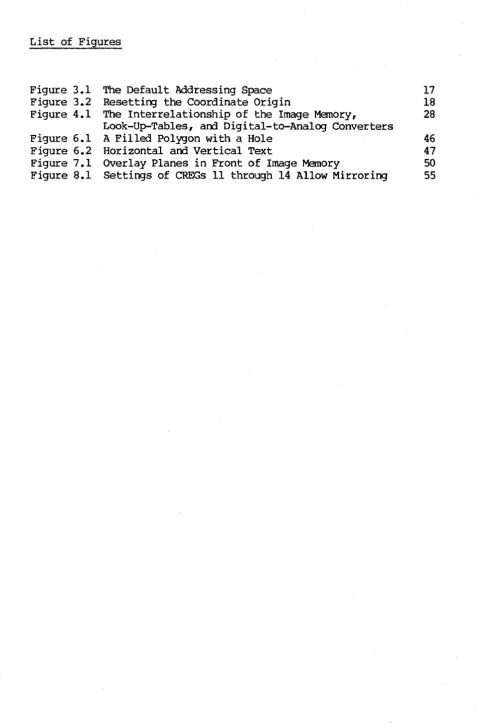
List of Figures
Figure 3.1 The Default Addressing Space 17 Figure 3.2 Resetting the Coordinate Origin 18 Figure 4.1 The Interrelationship of the Image Memory, 28
Look-Up-Tables, and Digital-to-Analog Converters
[image:7.615.50.551.48.775.2]List of Examples
Example 4.1 Example 10.1 Example 10.2 Example 10.3 Example 10.4 Example 10.5 Example 10.6 Example 10.7 Example 10.8 Example 11.1 Example 11.2 Example 13.1 Example 13.2
A Crawling Circle Demonstrates Shading Defining a Macro
Lots of Little Boxes
Another Fine-Shading Macro Interactive Cursor Tracking Display Pans Continuously Cursor-controlled Panning Button-controlled Zooming
Rubberbanding Lines Create a Pattern Using the DEBUG Command
Using the Local Debugger and the DEBUG Ccmnand Enter and Exit GRAPHICS Mode
Initializing ONELIB
26 63 64 65 66 66 67 67 67-68 71 71 76
Model One/25 Programming Guide
List of Tables
Table 2.1 Default I/O Buffer Sizes
Table 2.2 The Model One's Special Characters Table 3.1 Coordinate Register Assignments
Table 4.1 Cammon Look-Up-Table Routing Settings Table 4.2 Value Register Assignments
Table 4.3 PIXFUN Modes and Functions Table 4.4 Settings for bankm
Table 8.1 PM::TL Parameter Values
Table 11.1 Summary of Local D~ugger Commands Table 13.1 Raster COMMON Blocks
Table 13.2 ONELIB Error Codes and Messages Table 13.3 ONELIB Image Data Transfer Commands
15 15 21-22
29
34
1.0 INTRODUCTION
This manual describes, in detail, the standard commands of the Raster Technologies Model One/25. It is intended for the experienced graphics applications programmer, and assumes that the user has read the Introduction to the Raster Technologies Model One.
Before beginning this manual, the user should verify:
1. that the Model One/25 has been installed and tested on the host computer . system, and
2. that graphics commands may be successfully executed locally at the alphanumeric tenninal and from the host computer system.
Detailed installation and testing instructions are included Installation Guide for the Raster Technologies Model One.
in the
This manual has two parts: the first fifteen sections present the Model One and its commands in conceptual groups, using a tutorial structure; Section 16 provides an alphabetical command reference to all the Model One commands. Section 16 is intended for reference and gives complete details of every command. Finally, Section 17 provides a quick reference to the Model One corrmands.
Each Section is described below.
1.0 Introduction
2.0 Modes of Operation: this section describes the two operating modes for the Model One: ALPHA mode, in which the programmer communicates in alphanumerics with the host computer, and GRAPHICS mode, in which the Model One's command interpreter is used to decode and execute graphics commands. (Graphics commands may originate fram the host or fran the local terminal.)
3.0 Coordinates and Image Memory Addressing: this section Model One's two-dimensional coordinate addressing. origin, clipping window, screen origin, current point, registers are described in detail.
describes the The coordinate am coordinate
4.0 Pixel Values, Look-Up Tables, and Image Memory: this section explains the use of look-up tables (LUTs), value registers, and write- and read-enable masks. Pixel values and the pixel processor are explained. Blinking colors and the blink tables are descr'ibed; the CLEAR and FLOOD commands are also explained.
5.0 l024xl024 Addressing Mode: this section explains how to use the Model One/25 in 1K mode.
MOdel One/25 Programming Guide
in detail.
7.0 Dual-Overlay Planes: this section describes the Model One/25 dual-overlay planes and the associated commands. This section should be used only by programmers whose systems include the Option Card.
8.0 Pixel Mover: this section explains the Pixel Mover option, and should be used only by those programmers whose system includes the Option Card.
9.0 Data Read-Back and Image Transmission: this section describes loading image memory from the host computer and reading back infonmation to the host canputer.
10.0 Macro Programming: this section explains how to define, write, and execute a Model One macro program. Use of the button table, which may be used to execute macros under user control, is covered.
11.0 Application Development Features: this section describes the Model One local debugger, the cormnand stream translator, and the REPLAY corrmand (which allows the user to play back the last 32 characters sent fran the host to the Model One).
12.0 Programming the Z8000: this section describes the commands associated with downloading and debugging Z8000 object code. This section will be
needed only by those programmers who are adding commands to the Model One's command set.
13.0 Host FORTRAN Library: this section describes the MOdel One's host FORTRAN library in detail.
14.0 Host Computer DMA: this section describes the use of the Option Card DMA (Direct Memory Access) port for high-speed transfers between the host computer and the Model One's image memory. This section should be used only by those programmers whose system includes the Option Card.
15.0 Error Conditions: this section lists the possible error messages and their causes. The possible responses are given.
16.0 Alphabetical Command Reference: this section provides a complete reference to every MOdel One/25 command. Organized alphabetically, it supplies full details of all commands.
2.0 MODES OF OPERATION
The Model One functions in two modes: GRAPHICS mode, in which the Model One comnam interpreter decodes am executes graphics coomands, and ALPHA mode, in which ASCII characters are passed through the Model One to connect the local alphanumeric tenninal am the host computer •
. 2.1 ALPHA Mode
When the Model One is powered up, or if the RESET button mounted on the rear panel is pressed, a COLDstart command is executed. After COLDstart, the Model One is in ALPHA mode. You can then use the local alphanumeric terminal or keyboard to communicate directly with the host computer.
The Model One's mLDstart coomand, executed by pressing the RESET button or by entering the COLD command directly, perfonns a complete COLDstart on the Model One. The OOLDstart includes clearing defined macros, coordinate and value registers, resetting the clipping window, am setting the Look-Up-Tables to the default. Section 16 gives complete details of the OOLDstart command. You should execute a COLDstart command after each example in this manual to reset the Model One.
The Model One supports three different host transmission fonmats: 8-bit binary, ASCII hexadecimal, and pure ASCII. The choice between 8-bit binary and ASCII hexadecimal is made at installation, as described in the Model One Installation Guide. ASCII hexadecimal fonnat is used when the host computer cannot be programmed to transmit 8 bits of binary data over each character
sent to the ter.minal.
Pure ASCII fonnat allows the host computer to issue graphics cammands in exactly the same fonnat as commands typed at the local tenminal. The ASCII flag command is used to set the host interface for pure ASCII fonnat; all subsequent commands must be sent from the host to the Model One exactly as they would be typed in locally.
Pure ASCII fonmat requires many more characters to be sent from the host to execute a series of commands and should be used only when the command stream must be directly interpreted by the programmer or user rather than the Model One.
2.2 GRAPHICS Mode
In GRAPHICS mode, the Model One command interpreter decodes and executes graphics commands coming from the local tenminal or from the host computer. To enter GRAPHICS mode, a [CTRL-D] (04H or 84H) is' sent from the host camp.lter or fram the local ter.minal. The [CTRL-D] must be sent as a 7-bit ASCII character, independent of whether the the Model One has been set to accept data in 8-bit binary or ASCII hex. The SPeHAR (see section 2.3) comnand can
Model One/25 Programming Guide
Only one I/O port, either the port to the local tenninal (ALPHASIO port) or one of the ports to the host computer (HOSTSIO, HOSTGPIB, or HOSTDMA), can be
in GRAPHICS mode at any given time. When the ENTERGRAPHICS control character appears at one of these ports, the Model One enters GRAPHICS mode. Once the Model One is in GRAPHICS mode, the Model One expects graphics commands fran the host computer or from the local terminal, whichever one initially issued the ENTERGRAPHICS code.
2.2.1 GRAPHICS Mode From the Local Terminal
When the ENTERGRAPHICS control character appears at the Model One's ALPHASIO port, the local tenninal is put into GRAPHICS mode; the GRAPHICS pranpt character! is displayed at the terminal. Now, commands that you type are processed directly by the Model One and not sent to the host canputer.
The fonmat for graphics commands typed locally is:
COMMAND_MNEMONIC parameterl ••• parameterN
For example, the command to draw a circle of a given radius around the current point is:
CIRCLE 40
where CIRCLE is the canmand mnemonic, and 40 is the desired radius. Parameter values may be entered as signOO, base-10 numbers (such as 117 or 45), or as unsigned hexadecimal numbers when preceded by a
*
sign (such as #FF, #9E, or #OAOF).The parameter values must be separated by a canma or space, as desired. This can be used to set off sections of the commands, or to clarify what the command is doing:
Ale 10 45,135
This command draws an arc of radius 10, with starti~g angle 45 degrees and ending angle 135. You can also use commas to set off x,y pairs or groups of values, as you will see in the examples in this manual. Same further examples of locally-typed commands are:
MOVABS 0,0 DRWREL 30 150 VOCPAT #FOFO
The MOdel One command interpreter includes a HELP subsystem. list of all the Model One comnands, type
HELP
HELP may also be used to obtain parameter information, by typing
HELP COMMAND
For example, typing
HELP MOVABS
displays this infonnation:
MOVABS: OPCODE
=
001 1. <16 BIT SIGNED NUMBER> 2. <16 BIT SIGNED NUMBER>and typing
HELP PRMFIL
displays
PRMFIL: OPCODE
=
031 1. OFF ONAbbreviations may be used for the command mnemonic; these abbreviations are indicated in the Alphabetical Command Listing (section 16). The shortest abbreviation allowed is indicated by underscores: CIRCLE indicates that C is a valid abbreviation for the CIRCLE command. AdditTonal characters may be used, if desired: C, CI, CIR, CIRC, and CIRCL are all valid abbreviations.
The QUIT command is used to leave GRAPHICS mode and return to ALPHA mode. Type the ENTERGRAPHICS control character [CTRL-D] and then a QUIT command, to verify that the Model One returns to ALPHA mode. In ALPHA mode, you can once again use your tenminal to communicate with the host computer.
2.2.2 GRAPHICS Mode From the Host Computer
When the ENTERGRAPHICS character is sent from the host computer to the Model One, the host port which sent the ENTERGRAPHICS character, whether it was the HOSTSIO, HOSTGPIB, or HOSTDMA port, is put into GRAPHICS mode.
A host computer application program, using the Model One's Host FORTRAN library, sends the ENTERGRAPHICS control character by calling the subroutine ENTGRA. All graphics comnands from the host canputer to the Model One must be sent between a call to the ENTGRA subroutine and a call to the QUIT subroutine, as shown in the example below. (The host FORTRAN library is described in more detail in section 13.)
INTEGER I,J,K,L
INTEGER IRAn, lANG, IJANG
CALLENTGRA
Model One in ALPHA Mode No graphics commands may be
issued unti 1 a CALL ENTGRA corrmand is given.
Alphanumeric I/O is allowed.
Model One/25 Programning Guide
CALL MOVABS(I,J) CALL CIRCLE (M) CALL DRWABS(K,L)
CALL QUIT
·
·
CALL ENTGRA
·
·
CALL CIRCLE (IRAD)
CALL ARC ( IRAD, lANG, JANG) CALL DRAWBS (J , K)
CALL QUIT STOP
END
Graphics subroutine calls are allowed: no alphanumeric I/O to Model One.
Quit GRAPHICS Mode; return to ALPHA· Mode. Alphanumeric data
to local terminal allowed.
Reenter GRAPHICS Mode.
Exit GRAPHICS Mode.
If you are not using the Model One's host FORTRAN library, your program will have to send the ENTERGRAPHICS control code to the Model One in same other way. You should verify that your host programs can send the ENTERGRAPHICS control code and properly issue graphics commands before continuing. Graphics canmands from the host comfX,lter are composed of a stream of opcodes and parameters. Each opcode is one byte, ranging from OOH to FFH. The opcode for a MOVABS command is OlH. The opcode for a CIRCLE comnand is OEH. The M:>VABS command has four bytes of parameter data which must immediately follow its opcode. Thus, the byte stream for a complete M:>VABS corcmand would be:
OlH 03H FFH OOH OFH opcode parameters
This host command stream is equivalent to typing:
MOVABS #03FF,#OOOF
or
MOVABS 1023,15
at the local alphanumeric keyboard.
The CIRCLE command has one two byte parameter which gives the radius of the circle to be drawn. Thus, the CIRCLE command would be:
OEH OIH 03H opcode parameters
CIICLE #0103
or
CIRCLE 259
at the local alphanumeric terminal.
The QUIT conrnand, which returns the Model One to ALPHA mode, has an op:::ode of FFH (with no parameters). Each command stream to the Model One which is to be followed by normal terminal I/O must end wi th a QUIT corrmand. Thus, a complete command stream to the Model One would be:
04H (or 84H) OlH ENTERGRAPHICS opcode
03H FFH OOH OOH OEH parameters opcode
OIH 03H FFH parameters QUIT
Note that the ENTERGRAPHICS control code mayor may not have its high bit set; it is interpreted as a 7-bit ASCII code.
If the Hodel One has been configured to accept 8-bi t binary host transmission (see the Model One Installation Guide), each byte in the command stream is sent in a single character from the host computer. For 8-bit binary to work properly, the host computer may not use the eighth bit of each character for parity or force it high or low. It also must allow every control code to pass to the terminal. In addition, the host computer must not insert carriage control characters unpredictably into the output stream.
ASCII hex fonmat removes all of these restrictions at the cost of doubling the transmission time. In ASCII hex format, each byte is expanded into two hexadecLnal characters, one for the high nibble (four bits) of the byte,
follo~ by a second character for the low nibble of the byte. The byte stream
OIH 03H FFH OOH OFH
requires only five characters when using binary transmission. In ASCII hex, it would require ten characters:
"0" "1" "0" "3" "F" "F" "0" "0" "0" "F"
In ASCII hex fonmat, all carriage control characters are ignored, so that a FORTRAN WRITE statement or a BASIC PRINT statement will work properly.
2.2.3 The Model One's InEut and OutEut Buffers
While the local terminal is in GRAPHICS mode, any characters sent by the host to any of the Model One's host ports (HOSTSIO, HOSTDMA, or HOSTGPIB) are stored in the Model One's input queue until you type QUIT to reenter ALPHA mode. The HOSTSIO input queue defaults to 4096 bytes (characters) • The HOSTDMA input buffer is 2 characters.
Model One/25 Programming Guide
input queue holds 256 characters.
The ALPHASIO and HOSTSIO input queues can be changed with the CONFIG command; details are given in section 16.0.
Table 2.1 shows the default I/O buffer sizes for the MOdel One.
Port
HOSTS 10
HOSTDMA ALPHAS 10
HOSTGPIB Input 4096 2 256
o
Output 256 256 16o
Table 2.1 Default I/O Buffer Sizes
2.3 The MOdel One's Special Characters
The Model One responds to a set of special control characters, such as the ENTERGRAPHICS [CTRL-D] described above, to perfonn certain functions. These are:
Function
Enter GRAPHICS Mode Send BREAK to host Execute WARMstart Kill current line Backspace
ACKnowledge
Negative ACKnowledge Enter local debugger Suspend communications Restart communications
Default Special Character
[CTRL-D] [CTRL-P]
[CTRL- [] or [ESC]
@ [CTRL-H] [CTRL-F] [CTRL-U] [CTRL-X] [CTRL-S] [CTRL-Q]
Table 2.2 The Mbdel One's Special Characters
Note that [CTRL-S] and [CTRL-Q] are not sent to the host if you are not using the HOSTSIO port. They do, however, stop and start communications to the local terminal.
The SPCHAR char,flag,code command can be used to change the default special characters for the MOdel One. The most commonly modified default special character is the WARMstart character, which defaults to an ESCAPE. The SPeHAR command to change the ~start character to a [CTRL-G] (the bell) is:
The carmaoo
SOCHAR 2,0,0
disables the ~tart character entirely. (While this is dangerous during program development, it may be desirable after debugging has been completed.)
Model One/25 Programming Guide
3.0 COORDINATES AND IMAGE MEMORY ADDRESSING
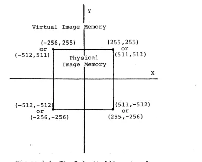
The Model One uses a two-dilnensional coordinate system to describe the graphic entities that are drawn into image memory. Each coordinate is stored as an X canponent am a Y canponent; these canponents are stored wi thin the Model One as two's ccmplement 16-bi t integers. The r-txlel One' s graphics commands use this 16-bit "address space" to specify the position of points, lines, circles, arcs, polygons, rectangles, and so on.
Because the physical ilnage memory of the Model One is not large enough to allow a full 16-bits of addressing in both the X and Y dimensions, the physical image memory covers only a patch of the 16-bit address space, ranging from (-256,-256) to (255,255) in the Model One/25 in 512x512 addressing mode and (-512,-512) to (511,511) in 1024x1024 addressing mode. (The l024xl024 addressing mode--also called 1K mode--is covered in more detail in section 5.0.) The patch of image memory is called the physical image memory, as it is that section of the virtual l6-bit address space that can be written into when making an image.
3.1 The Coordinate Origin
The CORORG x,y conmandcan be used, iIMlediately after a CX>LDstart, to reposition the physical image memory in the 16-bit address space. Figure 3.1 shows the default coordinate system for the Model One/25. Figure 3.2 shows the use of the CX>RORG corrmand to set up the screen so that (0,0) is in the lower-left hand of the screen and all points can be addressed as positive numbers.
Virtual Image Memory
(-256,255) (255,255)
or or
(-512,511) Physical (511,511) Image Memory
X
(-512,-512 (511,'-512)
or or
(-256,-256) (255,-256)
(
[image:19.615.122.517.413.729.2]y (511,511)
CORORG -256,-256
(0,0)
x
Figure 3.2 Resetting the Coordinate Origin
The CORORG command should be issued only immediately following a COLDstart, because all coordinate registers are modified by the CORORG command.
3.2 The Clipping Window
When a graphic primitive, such as a line or circle, is to be dr2!im, its coordinates are given as 16-bit addresses. When the primitive is then drawn by the Model One" it is clipped so that it is dr.awn only into the physical
image manory.
The Model One automatically clips all graphics primitives to a prer~t clipping window. If no clipping window was specified, it draws only that portion of all graphics primitives which lie in physical nnage memory. To support this clipping, the Model One maintains a clipping wirrlow; the clipping window defines a rectangular area of the virtual address space outside of wh.ich nothing is drawn. The defaul t clipping window is defined by the physical image manory. In the M:>del One/25, the default clipping window has the corners (-256,-256), (-256,255), (255,255), (255,-256). In the Model One/25 lK mode, the corners are (-5l2~-512), (-512!51l), (51l~511), and (51l~-512).
[image:20.612.113.463.60.370.2]Model One/25 Programming Guide
3.3 The Screen Origin
Ordinarily, the video monitor displays the entire contents of image memory. The displayed image is essentially a window into image memory, however, and it can be modified in both size and position.
The screen origin specifies the physical nnage memory location that will appear at the center of the screen; it may be placed on 4-pixel boundaries horizontally and 2-pixel boundaries vertically. The default screen origin is
(0,0) '"
The SCRORG x,y command is used to change the position of the screen orlgln within image memory. For example, SCRORG -40,-40 puts the point (-40,-40) at the center of the screen. If the image is large enough, wrapping around of the image can be seen when the corrmarrl is executed. The Model One automatically wraps the image around (side-to-side and top-to-bottom panning) when any part of the screen falls off the edge of physical image memory, as the screen refresh addresses are generated modulus 512 for 512 addressing mode or modulus 1024 for lK addressing mode. This wraparound cannot be disabled.
3.4 Display Scale Factor
The display scale factor determines the number of pixels that are displayed on the screen:
Scale Factor
1
2 4
8
512 Mode 5l2x5l2 256x256 l28xl28 64x64
3.5 Zooming the Display
1K Mode
1024xl024 (averaged to 512x512) 5l2x5l2
256x256 l28x128
The size of the window of image memory that is displayed is controlled by the ZOOM and ZOOMIN commands, which modify the display scale factor.
The ZOOM factor command allows explicit definition of the display scale; the display scale may be 1, 2, 4, or 8. For example, ZOOM 4 sets the display scale to 4.
The ZOOMIN command zooms in the display by a factor of two; ZOOMIN sets the scale to 4 if the current scale is 2, or 8 if the current scale is 4. Finally, if the current scale is 8, the display is restored to a scale factor of 1 by a ZOOMIN command.
ZOOM and ZOOM IN do not change the current screen origin, clipping window, or coordinate origin.
To zoom in a specific portion of the nnage, you should move that portion of the image to the center of the screen, using the OCRORG command, then execute the zoan cannarrl.
3.6 Inhibiting Screen Refresh
The BLANK flag command totally inhibits screen refresh, leaving image memory available all of the time for updates by the vector generator, pixel processor, or optional host DMA. BLANK 1 inhibits screen refresh: BLANK 0 restores nonmal screen refresh. When screen refresh is inhibited, the displayed image is forced to black.
The BLANK command can be used to increase the pixel writing rate, since more time is available for vector writing when screen refresh is inhibited.
3.7 The Current Point
All MOdel One commands which draw graphics primitives use the current point as a reference. For example, the CIRCLE command draws a circle of given radius around the current point.
To draw a line in hnage memory from a given starting point to a specified ending point, the current point must first be set to the starting point of the line. Then, the line is drawn fran the current point to the specified ending point. The line-drawing commands leave the end point of the line as the new current point after the line is drawn.
Five commands move, and therefore modify, the current point: MOVABS, l'{)VREL, M:>V3R, MOV2R, an:1 M:>VI.
The M:>VABS x,y command specifies a new current point: MOVABS -10,-10 sets the current point to (-10,-10).
The MDVREL dx,dy command moves the current point a relative distance from the previous current point. For example, the carmand sequence
MOVABS 143,271 MOVREL -10,-10
would place the current point at (133,261).
The MOV3R dx,dy andMOV2R dx,dy commands are special fonms of the l'{)VREL cannand for use when the displacenent to the new current point is small. The M:>V2R command requires only two bytes to be sent fram the host computer; the MOV3R comnand requires three bytes. The ~S and MOVREL cammands require five bytes when sent from the host. Details of the MOV2R and MOV3R commands are given in Section 16.0.
Model One/25 Programming Guide
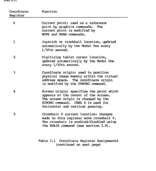
3.8 The Coordinate Registers
The Model One stores 64 coordinate registers internally. The coordinate registers store coordinate values within the Model One: some have a predefined function within the Model One, others are available for programmer
use.
Each coordinate register (CREG) stores a 16-bit X coordinate and a 16-bit y
coordinate. Table 3.1 shows the coordinate register assignments for the Model One/25.
Coordinate Register
o
1
2
3
4
5
Function
Current point: used as a reference point by graphics cannands. The current point is modified by MOVE and DRAW commands.
Joystick or trackball location, updated automatically by the Model One every 1/30th second.
Digitizing tablet cursor location, updated automatically by the Model One every 1/30th second.
Coordinate origin: used to position physical image memory within the virtual address space. The coordinate origin is modified by the CORORG command.
Screen origin: specifies the point which appears at the center of the screen. The screen origin is changed by the SCRORG canmand. CREG 4 is used for horizontal and vertical panning.
Crosshair 0 current location: changes made to this register move crosshair
o.
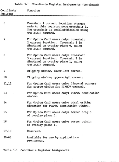
The crosshair is enabled/disabled using the XHAIR conmand (see section 3.9). [image:23.617.60.559.194.740.2]Table 3.1 Coordinate Register Assignments (continued)
Coordinate Register
6
7
8
9
10
11,12
13
14
15
16
17-19
20-63
Function
Crosshair 1 current location: changes made to this register move crosshair 1.
The crosshair is enabled/disabled using the XHAIR coomand.
For Option Card users only: crosshair 2 current location. Crosshair 2 is displayed on overlay plane 0, using
the XHAIR carmand.
For Option Card users only: crosshair 3 current location. Crosshair 3 is displayed on overlay plane 1, using
the XHAIR coomand.
Clipping window, lower-left corner.
Clipping window, upper-right corner.
For Option Card users only: diagonal corners for source window for PIXMOV command.
For Option Card users only: PIXMOV destination window.
For Option Card users only: pixel writing direction for PIXMOV destination window.
For Option Card users only: screen origin of overlay plane O.
For Option Card users only: screen origin of overlay plane 1.
Reserved.
Available for use by applications programner.
Table 3.1 Coordinate Register Assignments
[image:24.613.94.552.74.695.2]Model One/25 Programming Guide
The CLOAn creg x,y command loads a given 16-bit X coordinate and a 16-bit y
coordinate into the specified coordinate register. For example, CLOAD 25 -75,75 loads the point (-75,75) into coordinate register 25.
The CMOVE edst, csrc command copies data from one coordinate register into another: CMOVE 0 2 moves the contents of coordinate register 2 (the cursor location) into coordinate register 0 (the current point). The command CMOVE 0
2 thus specifies that the new current point is to be taken fram the cursor location on the digitizing tablet.
CADD csum, creg and CSUB edif, creg add and subtract coordinates between two specified coordinate registers: CADD 0 21 adds the contents of CREG 21 to the
contents of CREG O.
Note that in the coordinate register pairs specified as parameters for CMOVE,
CAnD, and CSUB, the register which is to be modifia:l is specifia:l first.
Several graphics pr imi ti ve canmands include an indirect addressing form. In this fODm, coordinates which are needa:l to execute the command are given by specifying a coordinate register instead of being supplied directly: MOVI moves to the point given by a coordinate register, RECTI uses a coordinate
register to specify the diagonal corner of a rectangle, and so on.
Finally, the command READeR creg reads or displays the contents of a specified coordinate register. For example, READeR 0 displays the contents of CREG 0
(the current point).
3.9 The Crosshairs
The XHAIR num,flag command controls the crosshairs. For the Model One/25, four crosshairs are available; two of these are optional and are drawn into the overlay planes. num gives the crosshair number; if flag=l, the crosshair is displaya:l. If flag=O, the crosshair returns to its default "invisible" state.
Crosshairs, when displayed, take their location fram the coordinate registers. Crosshair 0 uses CREG 5. Crosshair 1 uses CREG 6. For the crosshair to track the cursor on the digitizing tablet, it is necessary to write a small macro.
(Macro programming is describa:i in detail in section 10.)
MACDEF 10
CMOVE 5 2 Load crosshair 0 location with cursor location
MACEND
BUTTBL 0 10 Execute macro 10 every 1/30th second
Model One/25 Programming Guide
4.0 PIXEL VALUES, LOOK-UP TABLES, AND IMAGE MEMORY
The Model One's image memory can be used in several ways. In a fully-configured, 24-bit plane Model One/25, up to 24 bits per picture element
(pixel) can be used to store and display
a
5l2x5l2 image with a-bits of shading for each primary color. This allows 256 levels for each color: red, green, and blue; full-color imaging is thus provided, with over 16 million possible simultaneous colors.This full-color imaging configuration, where the red, green, and· blue components of the linage are stored independently, is most frequently used to display smoothly-shaded three-dimensional objects. In a full-color imaging application, the 24 bits per pixel of Dnage memory are divided into three banks: red, green, and blue.
In a Model One/25 with less than 24 bit planes, the Model One's image memory is used for pseudo-color (or false-color) imaging. In pseudo-color imaging, the Model One's three 5l2x5l2x8 L~age memory banks may not be fully populat9d, and the Model One's look-up-tables are then used to produce a color display. Also, a fully populated 24 bit per pixel Model One/25 can be used to store three independent Sl2x5l2x8 pseudo-color images.
In lKx1K addressing mode, the Model One supports up to 6 bits per pixel, allowing up to 64 simUltaneous colors (see Section 5).
4.1 Pixel Values
Colors for drawing graphics primitives are selected with the VALUE red,grn,blu command or stored in value registers. Value registers are analogous to coordinate registers and are described in more detail below. Combinations of red, green, and blue are used to create specific shades and varied colors.
Same examples are:
PRMFIL ON
~UE 255,0,0 Selects full-intensity red CIRCLE 100
VALUE 255,0,255 Selects full-intensity magenta CIRCLE 80
VALUE 255,255,0 Selects full-intensity yellow CIRCLE 60
~UE 255,100,100 Selects a shade of pink
MACDEF 10
VADD 0 10
CADD 0 21
Starts a macro definition
Add contents of value register 10 to value register 0
Add contents of coordinate register 21 to coordinate register 0
CIRCLE 50 Draw a circle
MAC END End macro definition
PRMFIL ON Draw filled graphics primitives VALUE 0,0,0 Set value te black
MOVABS -256,-256
VLOAD 10 1,0,0
Set current locatien to lower-left corner .of the screen
Load value register 10 with 1
CLOAD 21 1,1 Load coerdinate register 21 with (1,1) BUTTBL
°
10 Set up butten table to execute Macro 10every 1/30th .of a second
Example 4.1 A Crawling Circle Demonstrates Shading
AlIef the above commands are described in this manual; for the moment, you can enter them by typing an ENTERGRAPHICS character [CTRL-D] at the alphanumeric tenninal, then typing the commands exactly as they are written. Execution can be stepped by typing BUTTBL
° °
at the terminal.There are three commands available to specify the current pixel value. VALUE, which specifies a 24-bit pixel value, is described above. The other two commands are ~8 and ~lK; all three commands modify the current pixel value.
The current pixel value, stored in value register 0, gives the 24-bit value to be used whenever graphics primitives are drawn into image memory. For example, if yeu issue the drawing commands te draw a line into image memory, the line will be drawn using the current pixel value.
The VALUE r,g,b canmand specifies 24 bits of data, with 8 bits for each of the red, gr-een, and blue banks. The parameters .of the VALUE corrmand are red, green, and blue, in that .order. For example, ~UE 0,255,0 sets the current pixel value~ full-intensity green. The VALUE command is used for 24-bit full-color imaging applications.
Model One/25 Progranming Guide
In using the Model One for pseudo-color imaging, four special commands are available to optimize the number of bytes which must be transmitted from the host to specify the new pixel values. The four commands are VAL 8 , PIXEL 8 , RUNLN8, and LOT8. These commands end in 8, indicating that they are designed specifically for pseudo-color applications and systemss with less than 24 bit planes. Details of each command are given in the appropriate section8
The VALlK val command specifies the six bits of pixel value data for l024xl024 addressing mode and is described in more detail in Section 5.0.
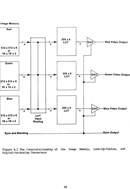
4.2 Look-Up Tables
Image Memory
Red
.,-,---.
~
256 x 8
1
J
-
J-
LUT, 8 r , 8 ,
8
512x512x8
V
Red Video Output
or 1Kx1Kx2
Green
J . . J i I
""'" 256 x 8 I
Ef-t 8 ~ t 8
-
LUT 18512 x 512 x 8
Green Video Output
or 1Kx1Kx2
Blue
J
..
,
..
256 x 8 I~B
' 8 r , I ..
-
LUTI .
e
---512 x ---512 x8 L-UT
lue Video Output
or Input
1Kx1Kx2 Routing
Sync and Blanking ~ ync Output
[image:30.615.56.558.59.791.2]Model One/25 Programming Guide
Each look-up-table drives one DAC: the red LUT drives the red DAC, the green LUT drives the green DAC, and the blue LUT drives the blue DAC. However, the input to a given look-up-table does not have to come from its respective bank of image memory. Figure 4.1 shows the LUT Input Routing block, which controls the correspondence between the banks of image· memory and the red, green, and blue LUTs.
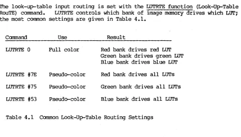
The look-up-table input routing is set with the LUTRTE function (Look-Up-Table RouTE) command. LUTRTE controls which bank of image memory drives which LOTi the most common settings are given in Table 4.1.
Canmarrl Use
LUTRTE 0 Full color
LUTRTE #7E Pseudo-color
LUTRTE #75 Pseudo-color
LUTRTE #53 Pseudo-color
Result
Red bank drives red LOT Green bank drives green LOT Blue bank drives blue LUT
Red bank drives all LOTs
Green bank drives all LUTs
Blue bank drives all LUTs
Table 4.1 Common Look-Up-Table Routing Settings
The Model One can be programmed to provide double buffering by writing into a single bank of image memory While driving all three look-up-tables from another bank, and switching between banks to change the display rapidly.
4.3 Using the Look-Up Tables
In a 24 bit-per-pixel system, the red, green, and blue banks of image manory dri ve the roo, green, am blue look-up-tables. The LUTs are then used to provide contrast or linearity correction to the displayed image. This direct correspondence (LUTRTE 0) is the default input routing on 24 bit plane Model One systems.
The look-up-tables are set to the system default at COLDstart. The default sets all three LUTs to a linear ramp with an index of 0 as the lowest intensity of the color, and 255 as full intensity. Combinations of red, green, and blue are used to create specific shades and variOO colors.
Six Model One commands are available to load the look-up-tables: LUTA, LUTB, LUTG, LUTR, LUTS, am LUTRMP.
[image:31.618.76.554.161.432.2]LUTB index, entry, LUTG index, entry, am LUTR index, entry: The LUTB corrmand sets a location in the blue look-up-table; LUTG sets a location in the green look-up-table; LUTR sets a location in the roo look-up table. For example, LUTR 100 255 sets location 100 in the red LUT to 255 (full intensity). If you did this after executing the series of commands above, you would see a sudden change to the displayed Unage as location 100 was changed. (This creates an arc of full intensity red.)
LUT8 index r ,g ,b: The LUT8 coamand changes the same location in all three look-up-tables to the three values specified. For example, LUT8 100 50,100,200 changes location 100 in all three LUTs: location 100 of the red LUT is changed to 50, location 100 of the green LUT to 100, and location 100 of the blue LOT to 200.
LOTRMP code sind,eind sent,eent: "ramp" of look-up-table values ..
The LUTRMP command is used to set a The ccm:nand includes five parameters:
code indicates the look-up-table to be loaded. code=l indicates the blue LUT.
code=2 indicates the green LUT. code=4 ind icates the red LOT. code=7 indicates all LOTs.
sind,eind these indicate the starting and ending locations within the look-up-table. sent,eent these indicate the starting and ending
values (entries) to be made into the look-up-table.
linear
For example, LUTRMP 4 0,255 255,0 totally reverses the power-up default entries in the red look-up-table. To go back to the example above (Example 4.1), if you typed in LUTRMP 4 0,255 255,0, you will see the background became red, the areas that were red become black--in general, the intensity components of the image will reverse.
LUTRMP 7 0 255
°
255 restores the power-on default contents of the red, green,and blue LUTs.
4.3.1 4-Bit Plane Model One Systems
In a Model One with four bit planes, the least significant four bit planes of the BLUE image memory bank have been populated. After power-on or COLDstart, the LUTRTE canmand should be issued:·
LUTRTE #53
CALL LUTRTE (83 )
when typed locally
When executed by an applications program fran the host
This LUTRTE carmand instructs the Model One to drive the RED, GREEN, and BLUE look-up-tables from the BLUE Unage memory bank.
RDMASK #OF
CALL RDMASK (15)
Model One/25 Programming Guide
when typOO locally
when executed by an applications program fram the host
You can now use a series of LOT8 commands to initialize the look-up-tablesto map the pixel values in image memory to the desired colors, as shown:
LtJr8
°
0,0,0 LtJr8 1 255,0,0 LtJr8 2 0,255,0 LtJr8 3 100,100,100canmand is used.
VAL83
FLOOD
LtJr8 3 100,255,100
VAL8 15
CIOCLE 50
Pixel value of 0 is black Pixel value of 1 is red Pixel value of 2 is green Pixel value of 3 is grey
For example:
Change the current pixel value to 3,3,3
Flood image memory with the current pixel value
Pixel value of 3 is light green Change current pixel value to
l5,15,15-the maximum for the 4-bit system
Draw circle of radius 50
In summary, for a four-bit plane MOdel One system, you should use the cannands
LUTRTE #53 RDMASK #OF
to configure the look-up-table routing, and then use the LOT 8 command to initialize the look-up-table entries from 0 to 15 to correspond with the sixteen simultaneously displayable colors you wish to use.
4.3.2 8-Bit Plane Model One Systems
In a Model One with eight bit planes, the BLUE image memory bank has been popula ted. After power-on or COLDstart, the LUTRTE cannarrl should be issued:
LUTRTE #53
CALL LUTRTE (83)
when typed locally
when executed by an applications program from the host
This LUTRTE coomarrl instructs the Model One to dr i ve the RED, GREEN, am BLUE
look-up-tables from the BLUE image memory bank.
You can now use a series of LUT8 coomands to initialize the look-up-tables to map the pixel values in image memory to the desired colors, as shown:
LOT8 0 0,0,0 LUT8 1 255,0,0 LUT8 2 0,255,0 LUT8 3 100,100,100
.
.
Pixel value of
°
is black Pixel value of 1 is red Pixel value of 2 is green Pixel value of 3 is greyLOT8 255 255,255,255 Pixel value of 255 is white
To change the current pixel value in a 8-bit per pixel system, the VAL8 canmand is used. For example:
VAL83
FLOOD
LOT8 3 100,255,100 VAL8 15
CIRCLE 50
Change the current pixel value to 3,3,3
Flood image memory with the current pixel value
Pixel value of 3 is light green Change current pixel value to
255,255,255--the maxDnum for the 8-bit systan
Draw circle of radius 50
In sunmary, for a eight-bit plane Model One system, you should use the ~ammand
LUTRTE #53
to configure the look-up-table routing, and then use the LUT8 corrmand to initialize the 1ook-up-table entries from
°
to 255 to correspond with the 256simultaneously displayable colors you wish to use.
4.3.3 l6-Bit Plane Model One Systems
In a Model One with sixteen bit planes, the GREEN and BLUE image memory banks have been populated. After power-on or COLDstart, the LUTRTE command should
be issued:
LUTRTE #75 when typed locally
to select the GREEN image memory bank, or
LUTRTE #53 when typed locally
to select the BLUE image memory bank.
To select the bank from an applications program:
CArL LUTRTE (117) to select the GREEN bank
or
, Model One/25 Programnling Guide
The LUTRTE #75 comnarrl instructs the Model One to drive the RED, GREEN, and BLUE look-up-tables from the GREEN image memory bank, which is necessary to display the contents of the GREEN bank.
The LOTRTE #53 carmand instructs the Model One to drive the RED, GREEN, and BLUE look-up tables fran the BLUE image manory bank, which is necessary to display the contents of the BLUE bank.
You can now use a series of LOT8 commands to initialize the look-up-tables to map the pixel values in image memory to the desired colors, as shown:
LUT8 0 0,0,0 LOT8 1 255,0,0 LOT8 2 0,255,0 LOT8 3 100,100,100
Pixel value of
°
is black Pixel value of 1 is red Pixel value of 2 is green Pixel value of 3 is greyLUT8 255 255,255,255 Pixel value of 255 is white
To change the current pixel value in a l6-bit per pixel system, the VAL8 command is used. You should also use the write-protect masks to control whether pixel data is written into the BLUE or GREEN bank. For example:
LUTRTE #75 WRMASK 255 2 VAL83
·CI~LE 25
LUT8 3 100,255,100 LUTRTE #53
WRMASK 255 1 VAL8 255
CIR:~ 50
LUTRTE #75
Select the GREEN bank for display write-enable the GREEN bank
Change current pixel value to 3,3,3 Draw circle of radius 25
Pixel value of 3 is light green Select the BLUE bank for display write-enable the BLUE bank
Change the current pixel value to 255,255,255 (maximum for l6-bit system) Draw circle of radius 50
Select the GREEN bank for display
In summary, for a sixteen-bit plane Model One system, you should use the command
LUTRTE #75
or
LUTRTE #53
to configure the look-up-table routing, and then use the LOT8 command to initialize the look-up-tab1e entries from
°
to 255 to correspond with the 256 simultaneously displayable colors you wish to use.4.4 The Model One's Value Registers
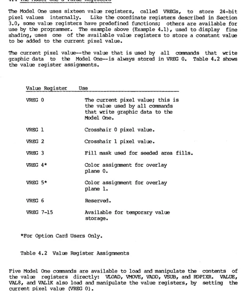
The Model One uses sixteen value registers, called VREGs, to store 24-bit pixel values internally. Like the coordinate registers describal in Section 3.0, same value registers have predefined functions; others are available for use by the programmer. The example above (Example 4.1), used to display fine shading, uses one of the available value registers to store a constant value to be added to the current pixel value.
The current pixel value--the value that is used by all coomands that write graphic data to the Model One-is always stora3 in VREG 0. Table 4.2 shows the value register assignments.
Value Register
VREG 0
VREG 1
VREG 2
woo
3VREG 4*
VREG 5*
VREG 6
VREG 7-15
Use
The current pixel value; this is the value used by all commands that write graphic data to the Model One.
Crosshair 0 pixel value.
Crosshair 1 pixel value.
Fill mask used for sea3ed area fills.
COlor assignment for overlay plane O.
COlor assignment for overlay plane 1.
Reserva3.
Available for temporary value storage.
*For Option Card Users Only.
Table 4.2 Value Register Assignments
Five Model One commands are available to load and manipulate the contents of the value registers directly: VLOAD, VMOVE, VADD, VSUB, and RDPIXR. VALUE,
VAL8, and VALIK also load and manipulate the value registers, by setting the current pixel value (VREG 0).
[image:36.613.58.554.89.688.2]Model One/25 Programming Guide
by the VADD command every time the macro is executed.
VMOVE vdst,vsrc moves the contents of one value register into another value register: VMOVE 10 11 copies the contents of value register 11 into value register 10.
VADD vsum,vreg and VSUB vdif,vreg add and subtract values between two value registers. As you saw above, VADD 0 10 adds the contents of value register 10 to the contents of value register 0; in the same way, VSUB 0 10 subtracts the contents of value register 10 from the contents of value register O.
RDPIXR vreg places the value found in image memory at the current point into the specified value register. RDPIXR 10 determines the value at the current point and then places that value into VREG 10. The RDPIXR command can be used
to select from a menu of colors, allowing the user to be given a choice of colors, select a color using the cursor, and make that color the current pixel value: RDPIXR 0 would make the pixel value at the chosen point the current pixel value.
The READVR vreg command does not affect the value within the value register: instead, the value of the specified VREG is displayed at the port that is in GRAPHICS mode (to the host if the host has sent the ENTERGRAPHICS character, to the local te~inal if the local terminal ·has sent the ENTERGRAPHICS character.
4.5 The Pixel Processor
Whenever pixel data is written into image memory, the Model One's pixel processor is used. The pixel processor performs ari ttInetic am logic functions between incoming pixel data and the pixel values which are already in image memory. The pixel processor supports addition, subtraction, and the logical functions XOR, AND, and OR.
The pixel processor has three independent a-bit arithmetic logic units (ALUs)--one for each of the red, green, and blue image memory banks. The pixel processor operates on data coming from the Model One's hardware vector generator (which may came from the host serial port or from the optional host DMA (Direct Memory Access) port). All graphics prllnitives are drawn into image memory by the hardware vector generator and are thus performed by the pixel processor.
Two commands control the pixel processor: PIXCLP and PIXFUN.
The PIXFUN mode command controls the arithmetic or logic function to be
Mode Mnemonic
0
1 INS 2 SUBI 3 SUBN 4 XOR
5 OR 6 AND
7 PRESET 8 CONDITIONAL
Pixel Function
Replace linage memory with incoming data
Subtract image memory data from incoming data Subtract incoming data from image memory Add incoming data values to image memory Exclusive OR incoming data values with
image memory
OR incoming data values with image memory AND incoming data values with image memory PRESET: write all l' s into image memory Conditional: inhibit writing of pixel values of (0,0,0). This mode is not available when performing a PIXMOV command.
Table 4.3 PIXFUN Modes and Functions
PIXCLP flag tells the pixel processor what to do if there is an underflow or overflow from an add or subtract operation on pixel values. PIXCLP 0
instructs the pixel processor ALUs to wrap-around on overflow or underflow; this effectively perfonns all computation modulus 256. PIXCLP I tells the pixel processor ALUs to clip their output to a maximum value of 255 or a minimum value of O. Clipping may be useful when intensity values from two images are to be added or subtracted, to avoid unexpected results. If PIXCLP
1 were set, the intensity would reach its maximum value without wrapping arourrl to black.
4.6 write-Enable and Read-Enable Masks
The MOdel One's image memory planes can be selectively read-enabled and read-disabled, write-enabled and write-protected.
The Model One's video output section includes an eight-bit register called a read-enable mask. The read-enable mask is ANDed with the data from image memory inmediately before the data enters the red, green, and blue look-up-tables: the same 8-bit read-mask is usej for all three LUTs. If a bit in the read-mask is zero, the corresponding input bit in all three LUTs is forcOO to zero.
The RDMASK mask ccmnand sets the read-mask. For example, RDMASK 0 sets the read-mask to all zeroes and thus completely suppresses display of the image, forcing the input to all three LUTs to O. (Note that this does not necessarily force the display to black; the display is dependent on the contents of the LUTs at index 0.) RDMASK #AA (hexadecimal) converts to alternating ones and zeroes, suppressing output of every other bit plane.
[image:38.615.55.555.83.429.2]Model One/25 Programming Guide
You should use the RDMASK command with caution because the Read mask register is logically "in front of" the look-up-tables. Thus, it has an effect on the addressing of the look-up-tables. For example, if you have the Read Mask set to #OF and then issue the command LUTA 255 255, you will actually change the
look-up-table value at address zero to (255,255,255), because of the masking of the higher-order bits by the Read Mask. NOTE: if you want to be sure you are changing only the correct look-up-table indices, you should first set the Read Mask to iFF, then issue the look-up-table commarrls, then reset the Read Mask to the desired value.
The WRMASK bibn,bankm cam\and selectively write-protects bit planes in the Model One's image memory. WRMASK uses two parameters: bitm and bankm. bitm is a single-byte mask controlling the write-protect status of each of the eight bit planes of image memory in all three image memory banks: each bit of bibn corresponds to one bit plane in all three banks. Whenever a bit of bibn is set, the corresponding plane in all three banks is writing-enabled. For example, setting bitm to iFO (hexadecimal) write-enables the four most significant bit planes in the red, green, and blue banks; the four least significant bit planes are write-protected.
bankm is a five bit mask: each bit corresponds to one of the three image memory banks and the two overlay planes. The least significant bit (bit 0) corresponds to the blue bank; bit 1 sets the green bank; bit 2 corresponds to the red bank. If any of these three bits of bankm are set, the corresponding bank of image memory is then wri te-enabled.
The WRMASKcammand can also be used to write-protect the optional overlay planes (see section 7.0), as shown in Table 4.4.
bits 7,6,5 bit 4 bit 3 bit 2 bit 1 bit 0
(bit O=LSB,
must be zero
if=l, write-enable overlay plane 0 if=l, write-enable overlay plane 1
if=l, wri te-enable roo image memory bank if=l, write-enable green image memory bank if=l, write-enable blue bnage memory bank bit 7=MSB)
Table 4.4 Settings for bankm
Thus, the bitm and bankm parameters of the WRMASK create a write-enable matrix (see Figure--i.2). A specific bit plane will be written only if'both bitm and bankm indicate that the plane is write-enabled. -WRMASK iF il write:enables only the four least significant bit planes of the blue bank; all other nnage memory bit planes are write-protected.
[image:39.618.86.567.227.601.2]green, arrl blue.
Read-masks may be used in conjunction with the write-enable masks in applications which use the 24 bit-plane capacity of the Model One to store multiple frames of a movie-loop animation sequence. The write-enable masks ensure that that only one frame at a time is written by the host; the read-masks and LOTRTE functions simplify the display of one frame at a time.
Section 10 (Macro Programming) gives examples of the use of the read-enable and write-enable masks for this type of animation.
4.7 Blinking Colors arrl the Blink Table
The Model One uses its look-up-tables and a blink table to provide blinking colors. The blink table lists addresses in the look-up-table; for each index, a pair of LOT entries is stored. The index specifies an address in the look-up-table: the contents of that address is toggled autanatically between the specified entries. The blink rate determines the amount of time each· entry stays in the look-up-table.
Four cannands are used for blinking colors: BLINKC, BLINKD, BLINKE, and BLINKR.
The BLINKC command clears the blink table and stops all look-up-tables from blinking. After clearing, the first value given (entryl of BLINKE) remains.
The BLINKD lut,index command removes a single entry fran the blink table and leaves the rest of the blink table intact. For example, BLINKD 7 100 disables blinking of address 100 in all look-up-tables.
The BLINKE lut,index entryl,entry2 command enables blinking of a specified index in the look-up-tables by making an entry in the blink table. For example, BLINKE 7 100 255 125 blinks location 100 in all look-up-tables between values 255 and 125. Up to 32 entries may be made in the blink table. The BLINKR frames command sets the blink rate. The blink rate can be set to a
multiple of the frame time (1/60th of a secorrl). For example, BLINKR 30 sets the blink rate to once per secorrl.
4.8 The CLEAR and FLOOD Commands
The CLEAR and FLOOD commands fill image memory with a uniform pixel value.
The CLEAR coomand fills the current clipping window as defined by CREGs 9 and 10 (WINDOW command) with the current pixel value. The selected pixel function (PIXFUN cammand) determines the actual pixel values that left in image memory when the CLEAR is done. For example:
VALUE 100,200,50 CLFAR
PIXFUN ADD VALUE 20,0,200 CLFAR
Model One/25 Programming Guide
All pixels in image manory would have (20,0,200) ADDed to their current pixel value of (100,200,50), resulting in a value of (120,200,250) in image menory.
The CLEAR command does not affect the current point.
The VECPAT mask command can be used to change the fill pattern for a CLEAR command, by specifying a pattern of pixels to be repeated along every scan line during the execution of the CLEAR ccmnarrl. mask is a 16-bit parameter; for example, VECPAT iAAAA contains alternating ones and zeroes. CLEARing the image memory with VECPAT iAAAA set will create a-dotted fill pattern. More infoDnation on the VECPAT command is given in section 6.2.
5.0 l024xl024 ADDRESSING MODE
The Model One/25 can also use its image memory as a l024xl024 array, instead of a 5l2x5l2 array. with a full memory configuration (24 bit planes), the Model One/2S can store up to 6 bit planes of image data at l024xl024. Each of the red, green, and blue banks stores l024xl024x2.
In l024xl024 addressing mode, the Model One/25's look-up-tables are bypassed. The output of the red, green, and blue banks are used to drive the red, green, and blue DACs (digital-to-analog converters) directly. The MODElK func command selects the pixel data routing. The command description in Section 16.0 gives full details.
The MODDIS flag command selects between the 512xS12 and 1024xl024 addressing modes:
MOODIS 1
sets the display mode to 1024xl024.
MODDIS 0
sets the display mode to S12x5l2 (the power-on default).
In addition, the MODDIS command clears image memory to a pixel value of (0,0,0) whenever the addressing mode is changed. Whenever MODDIS is executed, the look-up-tables and clipping window are reset to their default values. CREG 0, VREG 0, PIXE'UN, PIXCLP, PRMFIL, and DEBUG are also reset to their COLDstart default values.
The VALlK val command specifies the six bits of pixel value data which are needed for l024xl024 addressing mode. Two bits of data are used for each bank. (The format is packed red-green-blue, in a single byte.) The VALlK val command is the most efficient way of changing the current pixel value when running in l024xl024 addressing mode.
When reading back data to the host computer (see section 9.2 for details), the READF command allows you to select the appropriate format for reading back the pixel data. READF func, with func=4, will read back data to the host using the same format as the pixel values in the lK command. However, you should note that no image transmission commands are available to support this format, should you wish later to reload the Model One with the image. To store a complete ~age, you should use READF 0 and then restore the image with either RUNLEN or PIXELS.
Model One/25 Programming Guide
6.0 GRAPHICS PRIMITIVES
The Model One graphics primitive commands support local generation of common geometric entities: points, lines, circles, arcs, rectangles, polygons, and text. These entities are called graphics primitives and are used as building blocks for more complex images.
All commands which draw graphics primitives use the Model One's 16-bit virtual address space to define position and shape. The coordinate registers (current point, coordinate origin, and clipping window) control the placement of the graphics primitives within physical image memory, as described in Section 3.0, Coordinates and Image Memory Addressing.
6.1 Points
The simplest graphic entity, the point, is drawn with the POINT command~
POINT sets the pixel located at the current point (CREG 0) to the current pixel value (VREG 0); the current pixel value and current point are unchanged.
6.2 Lines
When drawing lines or vectors, the Model One uses the current point as the starting point for the line; a DRAW command then specifies the ending point of the line.
Five DRAW commands are available, which are analogous to the five MOVE commands described in section 3.7. All DRAW commands use the current pixel value to draw the line. The DRAW comnands are: DRWABS, DRWREL, DRW2R, DRW3R, and DRWI. The current point is always set to the endpoint of the line after the DRAW command has executed.
The DR~S x,y command draws a line from the current point to the given ending
point. The current point is set to (x,y) after execution. For example, DRWABS 10,10 draws a