Evaluating Kubernetes as an orchestrator of the
Event Filter computing farm of the Trigger and
Data Acquisition system of the ATLAS
experiment at the Large Hadron Collider
Giuseppe Avolio1,*, Mattia Cadeddu2, and Reiner Hauser3 1CERN, CH-1211 Geneva, Switzerland
2CERN, CH-1211 Geneva, Switzerland (on leave)
3Department of Physics University of Michigan, Ann Arbor MI
Abstract. The ATLAS experiment at the LHC relies on a complex and distributed Trigger and Data Acquisition (TDAQ) system to gather and select particle collision data. The Event Filter (EF) component of the TDAQ system is responsible for executing advanced selection algorithms, reducing the data rate to a level suitable for recording to permanent storage. The EF functionality is provided by a computing farm made up of thousands of commodity servers, each executing one or more processes. Moving the EF farm management towards a solution based on software containers is one of the main themes of the ATLAS TDAQ Phase-II upgrades in the area of the online software; it would make it possible to open new possibilities for fault tolerance, reliability and scalability. This paper presents the results of an evaluation of Kubernetes as a possible orchestrator of the ATLAS TDAQ EF computing farm. Kubernetes is a system for advanced management of containerized applications in large clusters. This paper will first highlight some of the technical solutions adopted to run the offline version of today’s EF software in a Docker container. Then it will focus on some scaling performance measurements executed with a cluster of 1000 CPU cores. In particular, this paper will report about the way Kubernetes scales in deploying containers as a function of the cluster size and show how a proper tuning of the Query per Second (QPS) Kubernetes parameter set can improve the scaling of applications in terms of running replicas. Finally, an assessment will be given about the possibility to use Kubernetes as an orchestrator of the EF computing farm in LHC’s Run 4.
1 Introduction
During Run 2, the Large Hadron Collider (LHC) [1] operated at a centre-of-mass energy of 13 TeV, with a peak luminosity of about 2.0 x 1034 cm-2 s-1 and more than 60 interactions per
*Corresponding author: [email protected]
bunch crossing. The High Luminosity LHC project (HL-LHC) [2], planned to start in 2026, will target a peak luminosity of 7.5 x 1034 cm-2 s-1 with more than 200 interactions per bunch
crossing. The HL-LHC upgrades will occur during the so-called Long Shutdown 3 (LS3, from 2024 to 2026). Therefore, the ATLAS [3] Trigger and Data Acquisition (TDAQ) system will undergo a substantial upgrade [4] in order to cope with the higher luminosity provided by the accelerator and exploit the HL-LHC physics potential.
The upgraded TDAQ system will sustain an input rate of 1 MHz (10 times more than in Run 2) with an average event size of about 5 MB (4 times more than in Run 2). It will include a large IT infrastructure, with thousands of computing nodes and applications to supervise. The Event Filter (EF) component of the TDAQ system is responsible for the reduction of the data rate to a level suitable for recording to permanent storage. The EF functionality will be provided by a large computing farm, made up of about 3000 hosts.
The Storage Handler component will stand between the detector read-out and the EF. The Storage Handler will buffer data received from the read-out (up to one hour of event buffering), actually decoupling the read-out and the EF operations. Therefore, the presence of the Storage Handler will allow to operate the EF in several different manners:
Decoupled or not from the LHC cycles. Executing prompt or delayed processing.
Hosting mixed workloads (e.g., Monte Carlo production).
A robust and reliable mechanism for the management of all processes running in the EF farm is a requirement to guarantee a stable and efficient execution of the EF service. The following chapters will focus on the evaluation of a possible candidate to orchestrate the EF computing farm operations.
2 Event Filter farm orchestration
The EF computing farm hosts both the processing units (PUs) and all the supporting services needed to implement the last step of the event selection of the TDAQ system. In modern software architectures, the management of large clusters of computing nodes is delegated to so-called “Cluster Orchestrator” services. In a system like the TDAQ, a Cluster Orchestrator will fulfill a series of well-defined requirements:
It will support different types of application lifecycles (i.e., always-running, run-to-completion and cron-like services).
It will allow both dynamic and static allocation of processes to computing nodes; It will be able to dynamically handle cluster resources (i.e., enabling/disabling
computation units at runtime, efficient exploitation of the available CPU power and memory).
It will scale to thousands of hosts.
It will control (i.e., start or stop) and monitor the status of all active processes. It will completely allow for the description of the requirements for every process
that needs to be started, including the definition of command-line parameters and environment variables to be passed to the executable.
A survey of the offers currently available on the open-source market (based on the requirements above) highlighted Kubernetes [5] to be an excellent candidate as an orchestrator for the EF computing farm. Kubernetes was announced by Google to the open-source community in 2014 [6] and is based on 15 years of experience at Google in managing
and orchestrating large clusters. Since its first release, the Kubernetes open-source community has experienced steady-growth, reaching more than 1500 commits per month and more than 150 contributors per month in February 2017 [7]. Today, Kubernetes is a mature product contributed to by several technology partners like RedHat, CoreOS and Intel.
Kubernetes can be described as “a system for automating deployment, scaling and management of containerised applications”. Among several supported features, Kubernetes provides a set of services facilitating easy and effective management of applications in a cluster:
Scheduling of applications based on required resources and other constraints. Automatic re-scheduling of applications when the application itself fails or the
node where the application is running dies.
Built-in support for service discovery and load-balancing.
Management of several storage back-ends, allowing transparent mounting of both local and network storage volumes.
Easy (via command line tools or GUIs) and automated (based on CPU usage) scaling of the number of application instances.
Kubernetes requires applications to be packed into software containers. Containers exploit virtualisation at the level of the operating system and are lightweight and simpler to build than Virtual Machines, which instead exploit hardware virtualisation. Packing an application into a container makes it possible to create immutable images disentangling the application itself from the host operating system. In such a way, containers not only provide strong resource isolation but also make the development, integration and deployment cycle easier, thus simplifying software portability and distribution. Kubernetes supports Docker [8] containers. Docker is currently the market-leading container platform.
3 Event Filter processing units in software containers
As a proof of concept, a small Kubernetes cluster (4 nodes) was set up using the CERN IT Virtual Infrastructure [9], with the goal of running EF Processing Unit (PU) instances in software containers. The PUs themselves were emulated with the offline version of today's EF software (i.e., AthenaHLT) using a realistic trigger menu. A Docker container image was created starting from a base SLC6 [10] image and adding a few additional packages. The EF software was retrieved directly from the CVMFS [11] installation repository. Kubernetes was able to mount the CVMFS volume (via a dedicated Flexvolume [12] driver installed on all the nodes) and transparently make it available to the containers, allowing keeping the size of the Docker image to a few hundred megabytes. In order to better simulate a data processing activity and mimic the future interaction between the EF and the Storage Handler, two additional mount points were added to the container: an input directory with data files containing real events, and an output directory receiving the results of event selection algorithms. The AthenaHLT image was distributed to and executed by the Kubernetes cluster. Events were correctly retrieved from the input data files and processed by the PUs, with selection results stored in the output directory.
4 Performance and scaling
satisfy this requirement Kubernetes fulfils two performance goals for the reported cluster size:
99% of the calls to its backend (e.g., the calls to inspect the state of a container) return in less than 1 s.
Containers (with pre-pulled images) are able to start within 5 s with a probability of 99% †.
It is worth noting that the performance goals were achieved with the cluster being fully populated; giving also an estimation of the time needed to restart a container in case of failures. Larger clusters are also supported, but with degraded performance.
The time needed to completely fill the cluster represents another crucial performance and scaling figure, particularly important for system operations. Since Kubernetes does not provide any official result in that respect, some specific and dedicated experiments were performed on a cluster made up of about 1000 virtual cores. The cluster was organised in the following way: one Kubernetes master node (32 CPU cores and 60 GB of RAM) and 240 slave nodes (4 CPU cores and 8 GB of RAM each). All the nodes were equipped with CPUs of the Intel Broadwell family clocked at 2.2 GHz. The latest Kubernetes version (1.5) available on the CERN virtual infrastructure was used.
The tests aimed at measuring the time needed to scale an application to a certain number of replicas (from one to five instances per host). In order to minimize the impact of the started applications on the measurement (i.e., they may consume CPU cycles competing with the Kubernetes system), a pause container was used and its image was pre-pulled into the cluster. Such a container sleeps for an undefined period of time after being started with very minimal resource usage.
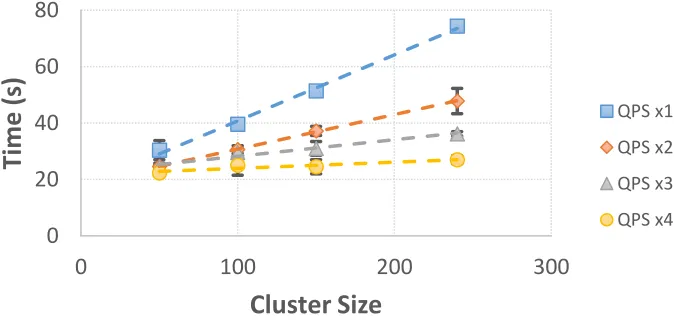
Figure 1 shows the time needed to scale the pause container up to five replicas per node as a function of the cluster size, for a total of 1200 started containers in a 240 host cluster.
Fig. 1. Time to scale the pause container up to five replicas per node as a function of the cluster size. The plot reports the measured times for four different values of the QPS parameter set.
† Performance of a big cluster is sensitive to the size of the Kubernetes “master” node (i.e., the cluster
control plane). The Kubernetes documentation indicates that the reported performance figures were achieved running tests on the Google Compute Engine using a n1-standard-32 [14] virtual machine for the master node.
0
20
40
60
80
0
100
200
300
Time (
s)
Cluster Size
satisfy this requirement Kubernetes fulfils two performance goals for the reported cluster size:
99% of the calls to its backend (e.g., the calls to inspect the state of a container) return in less than 1 s.
Containers (with pre-pulled images) are able to start within 5 s with a probability of 99% †.
It is worth noting that the performance goals were achieved with the cluster being fully populated; giving also an estimation of the time needed to restart a container in case of failures. Larger clusters are also supported, but with degraded performance.
The time needed to completely fill the cluster represents another crucial performance and scaling figure, particularly important for system operations. Since Kubernetes does not provide any official result in that respect, some specific and dedicated experiments were performed on a cluster made up of about 1000 virtual cores. The cluster was organised in the following way: one Kubernetes master node (32 CPU cores and 60 GB of RAM) and 240 slave nodes (4 CPU cores and 8 GB of RAM each). All the nodes were equipped with CPUs of the Intel Broadwell family clocked at 2.2 GHz. The latest Kubernetes version (1.5) available on the CERN virtual infrastructure was used.
The tests aimed at measuring the time needed to scale an application to a certain number of replicas (from one to five instances per host). In order to minimize the impact of the started applications on the measurement (i.e., they may consume CPU cycles competing with the Kubernetes system), a pause container was used and its image was pre-pulled into the cluster. Such a container sleeps for an undefined period of time after being started with very minimal resource usage.
Figure 1 shows the time needed to scale the pause container up to five replicas per node as a function of the cluster size, for a total of 1200 started containers in a 240 host cluster.
Fig. 1. Time to scale the pause container up to five replicas per node as a function of the cluster size. The plot reports the measured times for four different values of the QPS parameter set.
† Performance of a big cluster is sensitive to the size of the Kubernetes “master” node (i.e., the cluster
control plane). The Kubernetes documentation indicates that the reported performance figures were achieved running tests on the Google Compute Engine using a n1-standard-32 [14] virtual machine for the master node.
0
20
40
60
80
0
100
200
300
Time (
s)
Cluster Size
QPS x1 QPS x2 QPS x3 QPS x4The number of replicas was chosen to match the number of applications executed on each EF host during LHC’s Run 2 (as a reference, in Run 2 fully populating the EF cluster - 2000 hosts - took about 30 seconds). The size of the cluster could be easily changed by enabling or disabling the corresponding hosts in the Kubernetes scheduler. The measurements are reported for different values of the Kubernetes Query per Second (QPS) configuration parameter. The QPS set is used to set a limit on the maximum number of requests the different Kubernetes components can handle. In such a way it is possible to avoid overloading the system, resulting in a possible denial of service. The default QPS values are quite conservative and defined to safely allow Kubernetes to run on a wide range of hardware platforms. Tests were executed increasing QPS values to up to four times their defaults.
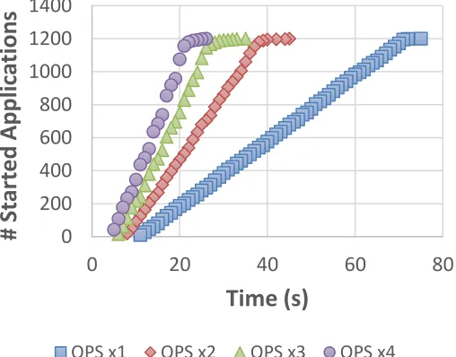
Kubernetes performance proved to be strongly dependent on the QPS configuration. As an example, the time to fully scale the pause container to 1200 replicas in a 240 hosts cluster decreased from about 74 seconds down to 27 seconds with the most aggressive QPS configuration. The impact of QPS settings can also be seen in Figures 2 and 3. The QPS value not only strongly impacts the rate at which Kubernetes manages to deploy applications, but it also has an impact on the time needed to start the first container (from 11 seconds down to 5 seconds for QPS values four times higher than the default configuration). At the same time it is evident how the time needed to have all the containers up and running is impacted by a few outlier instances beyond the 95th percentile. That behaviour could not be traced back to
any slow node in the cluster and needs further investigation in order to be properly understood. At the same time, it impacts performance figures only marginally.
Fig. 2. Number of started pause containers as a function of time for a cluster of 240 hosts and five replicas per host. Time is counted from the moment the command to deploy the containers is sent to Kubernetes. Measured times are reported for four different values of the QPS parameter set.
0
200
400
600
800
1000
1200
1400
0
20
40
60
80
#
St
ar
ted App
lic
at
ion
s
Time (s)
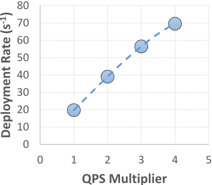
Fig. 3. Sustained rate of the pause container deployment for different values of the QPS parameter set. With QPS values four times higher than the Kubernetes default configuration, a sustained rate of 70 containers per second is reached.
5 Conclusions
In general, the executed tests demonstrated that:
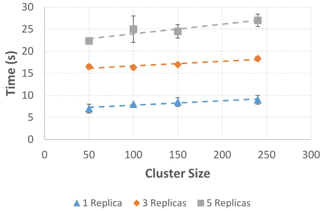
The Kubernetes container deployment rate in a cluster scales linearly with the size of the cluster itself. Assuming no higher order effects with larger clusters (Kubernetes officially supports 5000 hosts clusters), an EF PU service instance can be fully deployed on each node of a 3000 host cluster in about 35 seconds (Figure 4), matching the corresponding performance figures in Run 2 after a proper choice of the QPS values.
Kubernetes performance is highly dominated by its QPS configuration. QPS values four times higher than their defaults make it possible to reach a sustained deployment rate of almost 70 containers per second (to be compared to about 20 containers per second with the out-of-the-box configuration). The Kubernetes development road map aims to reach a rate of 100 containers per second on a 5000 host cluster in upcoming releases.
0
10
20
30
40
50
60
70
80
0
1
2
3
4
5
Depl
oy
men
t Ra
te
(s
-1
)
Fig. 3. Sustained rate of the pause container deployment for different values of the QPS parameter set. With QPS values four times higher than the Kubernetes default configuration, a sustained rate of 70 containers per second is reached.
5 Conclusions
In general, the executed tests demonstrated that:
The Kubernetes container deployment rate in a cluster scales linearly with the size of the cluster itself. Assuming no higher order effects with larger clusters (Kubernetes officially supports 5000 hosts clusters), an EF PU service instance can be fully deployed on each node of a 3000 host cluster in about 35 seconds (Figure 4), matching the corresponding performance figures in Run 2 after a proper choice of the QPS values.
Kubernetes performance is highly dominated by its QPS configuration. QPS values four times higher than their defaults make it possible to reach a sustained deployment rate of almost 70 containers per second (to be compared to about 20 containers per second with the out-of-the-box configuration). The Kubernetes development road map aims to reach a rate of 100 containers per second on a 5000 host cluster in upcoming releases.
0
10
20
30
40
50
60
70
80
0
1
2
3
4
5
Depl
oy
men
t Ra
te
(s
-1
)
QPS Multiplier
Fig. 4. Time to fully populate the cluster with pause containers as a function of the cluster size and for different number of replicas on each host. QPS values are set to four times the default Kubernetes configuration. Extrapolating the results for one replica to a cluster of 3000 nodes, the cluster itself would be fully populated in about 35 seconds.
Overall Kubernetes performance has proven to be sufficient for its usage as an orchestrator of the EF computing farm. Even so, it will be worthwhile to keep monitoring upcoming Kubernetes releases in order to track and verify evolving performance figures.
Acknowledgments
The authors would like to thank the CERN IT-CM-RPS section for the enormous and precious support provided to realize this work. Our gratitude goes especially to Ricardo Rocha and Spyridon Trigazis: nothing would have been possible without their precious help.
Appendix
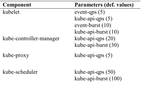
Several Kubernetes modules expose some QPS parameters, mainly to configure the interaction with the API server. As reported in the previous paragraphs, the out-of-the-box configuration resulted in poor performance in terms of container deployment rate. The QPS values can be modified applying changes to the command line parameters of the concerned modules. Table 1A reports all the parameters that have been modified for this study: the first column contains the concerned Kubernetes components, while the second column contains the corresponding command line option(s). Default values are reported in brackets and they were coherently scaled by a constant factor ranging from one to four.
0
5
10
15
20
25
30
0
50
100
150
200
250
300
Time (
s)
Cluster Size
Table 1A. QPS-related command line parameters that have been modified for each Kubernetes component. Default values are reported in brackets.
Component Parameters (def. values)
kubelet event-qps (5)
kube-api-qps (5) event-burst (10) kube-api-burst (10) kube-controller-manager kube-api-qps (20)
kube-api-burst (30)
kube-proxy kube-api-qps (5)
kube-scheduler kube-api-qps (50)
kube-api-burst (100)
References
[1] L. Evans and P. Bryant (editors), JINST 3, S08001 (2008)
[2] G. Apollinari et al., High-Luminosity Large Hadron Collider (HL-LHC): Technical
Design Report V. 0.1. CERN Yellow Reports: Monographs. CERN, Geneva, 2017
CERN-2017-007-M http://cds.cern.ch/record/2284929 [3] The ATLAS Collaboration, JINST 3, S08003 (2008)
[4] The ATLAS Collaboration, Technical Design Report for the Phase-II Upgrade of
the ATLAS TDAQ System CERN-LHCC-2017-020, ATLAS-TDR-029
https://cds.cern.ch/record/2285584?ln=en
[5] Kubernetes: Production-Grade Container Orchestration https://kubernetes.io/
[6] An update on container support on Google Cloud Platform
https://cloudplatform.googleblog.com/2014/06/an-update-on-container-support-on-google-cloud-platform.html
[7] The Kubernetes Open Source Project on Open Hub
https://www.openhub.net/p/kubernetes
[8] Docker: the world's leading software container platform https://www.docker.com/
[9] CERN Cloud Infrastructure https://openstack.cern.ch/
[10] SLC6: Scientific Linux CERN 6 http://linux.web.cern.ch/linux/scientific6/
[11] CernVM File System https://cernvm.cern.ch/portal/filesystem
[12] Kubernetes Flexvolume
https://github.com/kubernetes/community/blob/master/contributors/devel/flexvolum e.md
[13] Scalability updates in Kubernetes 1.6: 5000 node and 150000 pod clusters
http://blog.kubernetes.io/2017/03/scalability-updates-in-kubernetes-1.6.html
[14] Google Cloud Platform: Machine Types