ABSTRACT
LIU, YING. Shape Programming of Polymeric Materials from 2D to 3D. (Under the direction of Dr. Michael D. Dickey and Dr. Jan Genzer).
This Ph.D. dissertation focuses on converting planar two-dimensional (2D) shape programmable polymeric materials into three-dimensional (3D) shapes. The desire to create 3D shapes is based on the general premise that shape defines function in many materials. Working with 2D planar forms is appealing because they are compatible with many planar processes developed for semiconductor processing as well as other patterning techniques including screen printing, roll-to-roll processing, and inkjet printing. Specifically, my work is centered on developing assembly methods leading to generating 3D structures by employing out-of-plane sheet folding and on formation of buckled surface topographies from 2D forms.
We study macroscopic thermal shrinkage of the pre-strained polymer sheets as a function of temperature, time, and heating rate to provide information about the temperature required for folding to occur and to comprehend the kinetic of shrinkage of the polymer sheets during folding. A simple geometrical model that incorporates these macroscopic measurements predicts successfully the maximum bending angle as well as the dynamic bending angle for different hinge widths.
We demonstrate self-folding in planar polymer sheets using focused laser light. The laser power, intensity and beam width have been shown to control the folding time and the bending angle. The utilization of laser light is appealing because the approach requires no patterning of pre-defined hinges.
We also document the benefits of using light-emitting diodes (LEDs) as light sources for folding of polymer sheets. Selective wavelengths of the LED sources in conjunction with the color and width of the hinge regions enable us to fine-tune folding pathways within the sheets. We demonstrate that sequential folding (or rolling) can be realized by combining hinges with different degrees of light absorption (adjusted by varying the greyscales or color of hinges). The ability to program self-folding pathways can be potentially utilized in manufacturing grippers and actuators, and can be employed in folding of complex origami structures.
Shape Programming of Polymeric Materials from 2D to 3D
by Ying Liu
A dissertation submitted to the Graduate Faculty of North Carolina State University
in partial fulfillment of the requirements for the degree of
Doctor of Philosophy
Chemical Engineering
Raleigh, North Carolina 2013
APPROVED BY:
_______________________________ ______________________________
Jan Genzer Michael D. Dickey Committee Chair Co-Chair
________________________________ ________________________________ Gregory Parsons Jon-Paul Maria
DEDICATION
This dissertation is dedicated to my dearest parents and grandparents for their lifelong encouragement, support, sacrifices and love.
谨以此博士论文献给我最亲爱的父母和祖父母,
BIOGRAPHY
ACKNOWLEDGMENTS
First, I acknowledge my advisors Prof. Michael D. Dickey and Prof. Jan Genzer. I cannot survive my Ph.D. life without their valuable advice, great discussions, time investment, and encouragement. They are such great mentors who always support and trust in me, always present strong passion and positive thoughts to motivate the research, especially when I have hard time for the project. I also learn to fulfill multitask with effective time management, good cooperation, and strong communication skills from them as professional examples.
Next, I would like to thank Dr. Gregory N. Parsons, Dr. Veena Misra and Dr. Jon-Paul Maria for serving as my Ph.D. committee members and offering me helpful advice and valuable cooperation for projects we worked together.
I feel very lucky to have such nice and supportive group members: Rashed, Robin, Berc, Daniel, Mohammed, Collin, Duncan, Gilbert, Julie, Casey, Erich, Xiaojing, Preeta, Rohan, Matt, Phillip, Edwin, Sean, Eric, Moshe, Pandi, who help me in the lab work, train me for the use of the instruments, and provide great suggestion throughout my PhD research.
I would also like to thank Dr. Gregory N. Parsons, Dr. Jon-Paul Maria, Dr. Veena Misra, Dr. Saad Khan, Dr. Wesley Henderson, Dr. Orlin Velev and Dr. Michael Escuti for their generosity to allow me use instruments and software in their labs. I appreciate the help from the staff in the department of Chemical and Biomolecular Engineering too.
I am very grateful for my nice friends to have fun time together, give me passion and positive attitude what can help me overcome hard times. I really enjoyed the leisure and sports time with them.
Finally, I would like to express my deep gratitude to my beloved parents and other family members in China for always believing that I could achieve anything I believed and tried hard, and always showing me the positive attitude for life. The family reunion is always short for me when I had a trip back home in China from US, but all your love around is always endless power source to support me. There is a big thank for you.
TABLE OF CONTENTS
LIST OF TABLES....………. ix
LIST OF FIGURES....………... xi
CHAPTER 1 Introduction to Shape Programmable Polymers ... 1
Overview ... 2
1.1 Why Shape Programming from 2D is Interesting ... 4
1.2 Strategies of Converting 2D Plane to 3D Structure ... 5
1.2.1 Active Materials for Shape Programming ... 5
1.2.2 Approach to Shape Programming: Self-folding... 12
1.2.2.1 Designs of 2D Sheets for Self-folding ... 13
1.2.2.2 Different Stimuli Utilized for Self-folding ... 16
1.2.2.3 Management of Stress/Strain Gradient to Control Folding Process ... 18
1.3 Strategies of Converting 2D plane to 2D with Surface Topography ... 21
1.3.1 Surface Topography via Buckles Formation ... 22
1.3.1.1 Mechanism for Buckles Formation ... 24
1.3.1.2 Applications ... 30
1.3.2 Surface Topography via Shape Memory Effect ... 31
1.3.3 Surface Topography via Polymer Brushes ... 32
1.4 Summary and Dissertation Outline ... 33
References ... 36
CHAPTER 2 Self-folding of Polymer Sheets Using Local Light Absorption*... 50
2.1 Introduction ... 51
2.2 Experimental ... 54
2.3 Results and Discussion ... 55
2.4 Conclusion ... 65
2.5 Acknowledgements ... 66
References ... 67
CHAPTER 3 Modeling Self-Folding Kinetics Using Thermal Shrinkage of
Pre-strained Polymer Sheets* ... 74
3.1 Introduction ... 75
3.2 Experimental ... 76
3.3 Results and Discussion ... 77
3.4 Conclusion ... 90
3.5 Acknowledgements ... 92
References ... 93
Supporting Information ... 95
CHAPTER 4 3D Folding of Pre-Strained Polymer Sheets via Laser Light ... 100
4.1 Introduction ... 101
4.2 Experimental ... 102
4.3 Results and Discussion ... 102
4.4 Conclusion ... 111
4.5 Acknowledgements ... 111
References ... 112
Supporting Information ... 114
CHAPTER 5 Sequential Folding of Polymer Sheets via Color Selection ... 115
5.1 Introduction ... 116
5.2 Experimental ... 117
5.3 Results and Discussion ... 118
Sequential Folding via Applying Black Ink and Utilizing IR Heat Lamp ... 118
Sequential Folding via Applying Color Inks and Utilizing LED Lights ... 123
5.4 Applications of Sequential Folding... 131
5.5 Conclusion ... 132
5.6 Acknowledgements ... 133
References ... 134
CHAPTER 6 Formation of Isotropic Buckles on Polystyrene and Enhancement of its
Aspect Ratio ... 138
6.1 Buckles based on Polystyrene Laminates ... 139
6.2 Experimental ... 140
6.3 Results and Discussion ... 140
6.4 Effort to Enhance Limited Aspect Ratio of Isotropic Buckles ... 148
6.5 Buckles with Enhanced Aspect Ratio via Electric-field Amplification ... 152
6.5.1 Hypothesis of Electric-field Amplification... 152
6.5.2 Experimental ... 154
6.5.3 Results and Discussion ... 156
6.6 Summary ... 159
6.7 Acknowledgements ... 160
References ... 161
Supporting Information ... 164
CHAPTER 7 Summary and Future Outlook ... 166
7.1 Summary ... 167
7.2 Future Outlook ... 170
Appendices ... 174
Appendix A ... 175
LIST OF TABLES Chapter 1
Table 1.1 Representative research work on self-folding regarding different stimuli applied……….…..17 Table 1.2 The aspect ratio of buckles resulting from different UVO doses. The applied
axial strain is 50% for all samples, and the thickness of PDMS is ≈ 1 mm. The power density of UVO is 7.6 mW/cm2………..…26
Chapter 2
Table S2.1 Folding angles as a function of line width patterned across the narrow dimension of a Shrinky-Dink (L = 25 mm, L’ = 10 mm)……….71 Table S2.2 Folding angles for double-line hinges as a function of line spacing on
Shrinky-Dinks (25 mm x 10 mm). Two lines (each with a width of 1 mm) were patterned parallel to each other across the center of the sheet with a space placed between the lines………..…..71
Chapter 3
Table S3.1 Parameters of the exponential fitted curves using Equation (3.2):
( ) ,in different isothermal conditions for the isothermal shrinkage of
pre-strained sheets……….96 Table S3.2 Parameters of the exponential fitted curves using Equation (3.4):
[ ( )] , at different heating rates for the non-isothermal
shrinkage of pre-strained PS sheets………...…97 Chapter 5
Table 5.1 Key process parameters important for sequential folding…….…….…..…127 Table 5.2 Examples of color selection for sequential folding. 1st hinge represents the hinge which folds first in that case, while 2nd hinge represents the hinge which folds following 1st hinge. Yes or No represents folding or no folding separately……….130 Table S5.1 Measured power density for different LED lights used for the folding
Chapter 6
Table S6.1 Spin conditions used to spin-coat PS films in our experiment…….……....164 Appendix A
Table A1 Transmission, sheet resistance and roughness of as-sputtered and commercial ITO………...180 Table A2 Short-circuit current densities (Jsc), fill factors (FF), open circuit voltages
(Voc) and efficiencies of OPV based on P3HT:PCBM blends with and
without post-annealing and with different active
areas……….……….……..184 Table A3 Short-circuit current densities (Jsc), fill factors (FF), open circuit voltages
(Voc) and efficiencies of OPV based on solutions with different concentrations….……….186 Table A4 Short-circuit current densities, open-circuit voltages, fill factors and
efficiencies for devices with different device
LIST OF FIGURES Chapter 1
Figure 1.1 Cross-sectional illustration of strategies to generate 3D shapes by using shape programmable polymeric materials in two categories: 3D structures by out-of-plane bending or folding, and 2D in-plane form with surface topography………..3 Figure 1.2 (a) A typical piezoelectric materials with the electrodes applied on the top and bottom faces. The dash lines sketch a deformed shape in response to the electric field26; and (b) Schematic of piezoelectric PVDF films used as a pressure sensor due to the deflection.21………..6 Figure 1.3 3D coil induced by local bending due to ionoprinting of a copper wire on
pNaAc gel. A consequent gel gripper is demonstrated to catch and release a small blue cube of PDMS (~1g) in ethanol and water respectively. The scale
bar is 10 mm.39………8
Figure 1.4 (a) SMA actuators can be folded by applying Joule-heating (red arrows show the heating direction). b) Demonstration of folding a “boat” from a 2D planar composite sheets patterned with SMA hinges which can cause the
folding through Joule-heating.1………...9
Figure 1.5 Photographs of folded cubes from a pre-programmed 2D SMP sheet.54...11 Figure 1.6 Schematics of the comparison between self-assembly and self-folding...12 Figure 1.7 Schematics of different designs on 2D planar template for self-folding in cross-sectional view. (a) heterogeneous “hinge” materials (red) embedded in the bulk materials ; (b) bilayer structure with one responsive layer (red); and (c) pre-programming of homogeneous materials………..13 Figure 1.8. Schematics of bending of bi-metal strip.102 E1 and E2 are elastic moduli; α1
and α2 are thermal expansion coefficients for two layers separately; h1 and h2 are film thicknesses; and h is total thickness. P1 is tensile force for layer 1 and P2 is compressive force for layer 2……….18 Figure 1.9 a) Schematic of the formation of buckles on an elastic substrate; b) optical
optical microscopy image of isotropic buckles (oriented in random
directions).120……….23
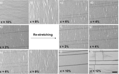
Figure 1.10 a) Photograph of the custom-designed stretcher. The sample such as a PDMS sheet is sandwiched tightly by screws, the sample is stretched axially (labeled in red) by rotating the shaft (labeled in blue); b) AFM image of unidirectional buckles on stretched PDMS with air plasma treated surface and c) Map scan by profilometry of unidirectional buckles on stretched PDMS with UVO treatment………..………25 Figure 1.11 Hierarchically-buckled topography due to large strain applied to UV/Ozone-treated PDMS. a) Illustration of hierarchically-buckled topography; b) hierarchical profile collected by profilometry and c) wavelengths of multiple generations of buckles as a function of applied strains. 119………..….26 Figure 1.12 Optical microscopy images of buckles formation when releasing and re-applying strain on an ITO sputtered PDMS sheet. The image was first taken right after ITO sputtering (ɛ ≈ 10%), more images were taken when slowly releasing the strain from 10% to 2%. The film was re-stretched after total release (ɛ ≈ 0%) to ɛ ≈ 10% and overstretched to ɛ ≈ 12%. The images were taken consecutively (scale bar: 20 µm for all images)………..28 Figure 1.13 (a) Schemcatic, optical microscopy image and 3D profilometer image of
isotropic buckles formed due to spontaneous swelling of a gradient crosslinked UV-curable resin (2-phenoxyethyl acrylate, crosslinker is 1,6-hexanediol diacrylate, photoinitiator is Irgacure 184). 130 (b) Optical microscopy images of ordered buckles on Polyacrylamide/NP-TiO2-CTAB PVP hybrid gel before and after water vapor treatment. (CTAB: cetyltrimethylammonium bromide; NP-TiO2: titania nanoparticles).131 (c) Schematic of reversible surface buckles of UVO-treated PDMS to oxidize the surface due to the swelling in response to different solvents.132……….30 Figure 1.14. Surface topography due to shape memory effect in an acrylate-based SMP
heating at ~120 °C. The pattern has a pitch of ~ 800 nm and a height of ~
180 nm.141……….…32
Chapter 2
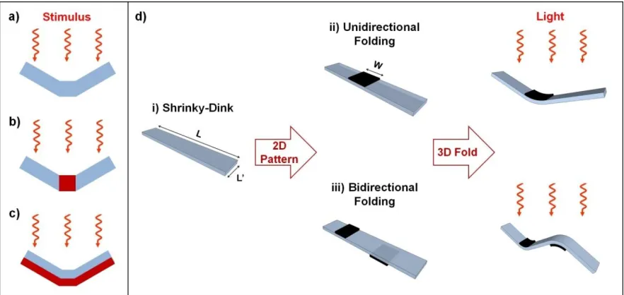
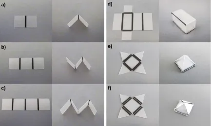
Figure 2.1 Schematic of different approaches to self-folding via thermal actuation (a-c are in cross-sectional view). Previous approaches include folding induced by25: a) pre-programming of shape memory polymers; b) responsive hinges (red) composed of materials that differ from the bulk (blue); c) expansion mismatch of multilayer film stacks; and d) Our approach uses a uniform sheet and an even stimulus that is localized by surface patterns: i) A plain Shrinky-Dink; ii) Unidirectional folding via absorption of light by black ink (width, w) patterned on one side of the Shrinky-Dink; and iii) Bidirectional folding due to ink on both sides of the transparent Shrinky-Dink. Due to effective light absorption by the ink, the polymer under the black ink heats up faster than the rest of the polymer. The thicknesses of polymer films and black ink are not drawn to scale………54 Figure 2.2 Photographs of 3D structures created by self-folding of Shrinky-Dinks patterned with a desktop printer. a) Single line (w = 1 mm, L’ = 10 mm) patterned on the top side of the Shrinky-Dink; b) two lines (w = 1 mm, 12 mm spacing, L’ = 10 mm) patterned on either side of the Shrinky-Dink; c) three lines patterned on alternating sides of the Shrinky-Dink (w = 1 mm, 12 mm spacing, L’ = 10 mm); d) rectangular box (20 mm x 10 mm x 10 mm, w = 1.5 mm); e) tetrahedral box (w = 2.0 mm); and f) tetrahedral box with adjacent double hinges (w = 1.0 mm, inter-hinge spacing 0.3 mm). Both tetrahedrons have a square bottom facet (10 mm x 10 mm) and equilateral triangles on the other facets………..57 Figure 2.3 a) Experimental time needed to initiate folding (folding,exp) as a function of
Figure 2.4 Simulated cross-sectional temperature profiles on the top (solid lines) and bottom (dotted lines) sides across the length of Shrinky-Dinks with different line widths (w = 0.5 mm and w = 2.0 mm) at two different support temperatures (TS = 20 °C and TS = 90 °C. a) w = 0.5 mm, TS = 20 °C; b) w = 2.0 mm, TS = 20 °C; c) w = 0.5 mm, TS = 90 °C; and d) w = 2.0 mm, TS = 90 °C. Each profile depicts a snap-shot of the temperature near the patterned line when the top central surface first reaches 120 °C. Times listed in each panel indicate response times for onset of folding as determined from the COMSOL simulation………..62 Figure 2.5 Depiction of a folding / unfolding scenario. A grain of rice (left) can be
packaged into a self-folded box (center). Uniformly heating the box above the glass transition temperature causes it to unfold and shrink in plane (right)………64 Figure 2.6. Demonstration of some origami structures induced by self-folding utilizing
Figure S2.4 Colored maps of the modeled temperature profile in the cross-section of a Shrinky-Dink during the first 4.2 seconds of exposure at TS = 20 °C. The heat originates from the top surface, which is the location of the ink. The two vertical dashed lines represents the patterned line width (w = 1.5 mm)………73 Figure S2.5 Photographs of (a) a 2D Shrinky-Dink (diameter 10 mm) patterned with
black toner in the shape of a concentric circle (w = 1 mm, outer diameter 6 mm) and (b) the resulting 3D saddle structure that forms upon exposure to light………73
Chapter 3
Figure 3.1 Temperature dependence on the exposure time to a heat lamp for a plain pre-strained PS sheet (open symbols) and a pre-pre-strained PS sheet printed with black ink (solid symbols). Photographs of representative black and plain PS sheets depict the geometry for selected data points. Curled samples are flattened for imaging. The PS sheets (initial dimension 20 mm x 20 mm) rest on a hotplate at 90 °C during the exposure to IR light………...78 Figure 3.2 Thermal shrinkage of pre-strained PS sheets (initial dimension 20 mm x 20 mm) as a function of heating time at a constant temperature. The symbols represent the experimental data and the lines are best fit curves using Equation (3.2). The inset magnifies the data from 0 to 50 s………80 Figure 3.3 (Left) Ultimate shrinkage (S∞) of PS sheets as a function of temperature
during isothermal heating. The line is the best fit to the experimental data using Equation (3.3). (Right) Dependences of the shrinkage constant (kt) on temperature during isothermal heating. The values of kt have been obtained by fitting the data in Figure 2 to Equation (3.2). The slopes give activation energy for thermal shrinkage of PS above and below the critical temperature required for self-folding………82 Figure 3.4 (Left) Thermal shrinkage of pre-strained PS sheets (initial dimension 20 mm
Figure 3.5 (Left) Side-view schematic of the polymer sheet (blue) and ink (black) depicting the simple geometrical model used to calculate the bending angle. (Right) Bending angles (αB) as a function of hinge width obtained from experiment (circles) and calculated using the geometric model (squares). Experimental data were collected form pre-strained PS sheets as depicted in top-view schematic (initial dimension 25 mm x 10 mm) with a single line of ink patterned across the center of the sample resting on hotplate at 90 °C and exposed to external IR light at a distance of 5 cm………88 Figure 3.6 (Left column) Temperature of the inked hinge, Th (solid squares) measured
by IR camera. (Middle column) Thermal shrinkages of the PS sheets on the top surface (solid circles) derived from the temperature temporal profile. (Right column) Experimental bending angle change with time (solid triangles) compared with bending angle calculated based on the thermal shrinkage derived from the temperature temporal profile (open triangles). The different rows correspond to data with different hinge widths, W, equal to (from top to the bottom): 1.0, 1.2, 1.5, and 2.0 mm………..90 Figure S3.1 (Left) Representative in-plane shrinkage of the pre-strained PS sheets in both X and Y directions with time at a constant temperature of 110, 120 and 160 °C. The experiment is operated in a hot stage at constant temperatures. (Right) Representative in-plane shrinkage of the pre-strained PS sheets in both X and Y directions with time at a constant heating under the exposure to IR light (479 °C /min and 142 °C/min) and in the hot stage (20 °C/min). All samples (initial dimension 20 mm x 20 mm) rest on a hotplate at 100 °C or with the initial temperature at 100 °C in the hot stage………..95 Figure S3.2 Thermal shrinkage of the pre-strained PS sheets (initial dimension 20 mm x 20 mm) as a function of temperature during constant heating rate. Experimental shrinkage data are realized by using hot stage (blue), halogen lamp (green), and IR lamp (red), respectively. The numbers in the parentheses denote different heating rates (in C/min). The lines are best fits to Equation (3.4): ( ) ………98 Figure S3.3 Temperature of ink patterned pre-strained PS sheets as a function of time.
sample. All samples (initial dimension 10 mm x 10 mm) rest on a hotplate at 90 °C during the light exposure………98 Figure S3.4 Bending angles (αB) as a function of hinge width obtained from experiment
(circles) and calculated using the geometrical model (squares). Experiment data were collected form pre-strained PS sheets (initial dimension 10 mm x 25 mm) with a single line of ink patterned across the center of the sample resting on hotplate at 90 °C and exposed to external IR light at various distances (5, 10, and 15 cm)………..99 Figure S3.5 Thermal shrinkage of black ink patterned pre-strained PS sheets (initial
dimension 20 mm x 20 mm) as a function of temperature under the IR lamp exposure at the distance of 5 cm from the sample. The line represents the best fit to Equation (3.4): ( ) . S 55% is assumed. The samples are rested on the hotplate at 90 °C………99
Chapter 4
Figure 4.1 Photographs of the folding of a pre-strained polymer sheet coated with black ink triggered by IR laser light. The sample is 10 mm x 50 mm and is irradiated with a laser beam that spans the width of the sample and irradiates from the left side of the images. The beam, though not visible to the naked eye, can be clearly seen in the captured images impinging on the sample at times 1 and 2 s. The sample is held in place at the bottom by a clamp supported by a laser table………103 Figure 4.2 Bending angle and onset time of folding as a function of laser incident power
or incident intensity when the folding is triggered by IR laser light in a static linear manner. The samples are black ink coated pre-strained polymer sheets (4 mm x 40 mm)………..106 Figure 4.3 (a) Temperature profiles in 3D from the simulation of COMSOL multiphysics; (b) Cross-sectional schematics of heat loss on the edge of the hinge. W1 and W2 are the beam widths, and d is the dimension of the edge for heat loss (outlined by dashed line and noted by yellow arrows); and (c) Onset energy as a function of onset time of folding for various beam widths (legend) and incident intensity (color scheme)………...109 Figure 4.4 Fitting parameters for the inflection point, I0 obtained from the bending angle
Figure S4.1 UV-Vis Spectra of plain pre-strained polymer sheets and black ink printed pre-strained polymer sheets……….114 Figure S4.2 The relationship between onset time and total time of folding. (Legend: laser beam width in the unit of microns)………..114
Chapter 5
Figure 5.5 Absorption spectra of color inks printed on plain pre-strained polymer sheet and plain sheet. Dash lines represent the typical wavelengths for blue (470 nm), green (530 nm) and deep-red (660 nm) LEDs as shown in inset photos………..124 Figure 5.6 (a) Photographs for “sequential folding” by utilizing the hinges in yellow (in
Figure S5.3 Dependence of onset time (left) and bending angle (right) for folding on the key process parameters (i.e., ink absorption and light intensity) for different hinge widths of (a) 1.0 mml (b) 1.5 mm; and (c) 2.0 mm………..137
Chapter 6
Figure 6.1 AFM images of isotropic buckles based on ITO (40 nm)/PS (200 nm) bilayer resting on top a silicon substrate. 2D top view (a) and 3D tilt view (b). The wavelength is ≈1.76 µm and the aspect ratio is ≈0.06……….141 Figure 6.2 Investigation of buckle formation on ITO (thickness ~100 nm) coated
free-standing PS sheet under optical microscope under (a) 1000X and (b) 200X magnifications……….142 Figure 6.3 Optical microscope images of isotropic buckles based on ITO (40 nm)/PS films with different thicknesses of PS (a) 150 nm; (b) 370 nm; (c) 530 nm and (d) 650 nm on a silicon substrate. The ITO thin film was deposited by 20W RF sputtering with 4 mTorr Ar pressure. The sample was heated on the hotstage with the heating rate of 10 °C/min from room temperature to 120 °C. The scale bar is 100 µm………144 Figure 6.4 Real-time investigation of isotropic buckles based on an ITO (50 nm)/PS (1.5
buckles on 0.5 µm thick PS film and (b) e-field buckled on 5 µm thick PS film………..159 Figure S6.1 Film thickness as a function of the concentration of polystyrene stock solution
(wt%) in toluene and spin speed for coating process based on (a) results from literature;26open circles represent 0.5 wt%; open square 1 wt%; open diamond 2 wt%; “X” represents 4 wt%; “+” represents 6 wt%; open triangle represents 8 wt%; solid circles represent 10 wt%; solid squares represent 15 wt%; solid diamond represent 20 wt% and solid triangles represent 30 wt%, and (b) our experimental results.14………..164 Figure S6.2 Real-time investigation of isotropic buckles based on ITO (40 nm)/PS (500 nm) bilayer on a silicon substrate. The buckles start to grow around temperature of 107 °C, and then fully grow on the show surface and remain when the sample is cooled down. ITO thin film is deposited by 20W RF sputtering with 4 mTor process pressure. The sample is heated in the hot-stage with the heating rate of 10 °C/min from room temperature to 120 °C. The scale bar is 100 µm………..165
Appendix A
Figure A.1 Schematic of photocurrent generation in an OPV.8 (a) photon absorption; (b) exciton diffusion; (c) separation of an exciton at heterojunction and (d) transport of charge carriers (electrons and holes)………176 Figure A.2 Previous work on light trapping in OPVs based on a) microprism;18 b) lambertian light scatterer;20 c) V-shaped/W-shaped configuration24 and d) surface relief gratings pattern.22...178 Figure A.3 Similar transmission spectra of as-sputtered ITO/glass compared with that of
commercial ITO/glass in the range from 400 nm to 650 nm………..181 Figure A.4 Amorphous as-sputtered ITO and crystalline commercial ITO from XRD
profiles……….181 Figure A.5 Photographs of reference device layouts on a) commercial ITO; b) homemade device on as-sputtered ITO with large active area and c) homemade device on as-sputtered ITO with small active area. The substrates are 1x1
Figure A.6 Current density-voltage curves for the reference device and the homemade device. Reference device: Voc=0.42 V; Jsc=6.36 mA/cm2; PCE=1.18%; FF=0.45. Homemade device: Voc=0.40 V; Jsc=4.80 mA/cm2; PCE=0.65%; FF=0.34………...183 Figure A.7 Current density-voltage curves for device without post-annealing (left) and
with post-annealing (right)………..185 Figure A.8 Photographs of P3HT:PCBM films cast from different concentrations: a) 10:8
mg/ml P3HT:PCBM solution, spin speed is 600 rpm for 60 sec and b) 20:16 mg/ml P3HT:PCBM solution spin speed is 2000 rpm for 60 sec………...186 Figure A.9 Photographs of different device layouts: a) crossed layout and b) central
layout……….………..187 Figure A.10 Schematic of the set up for I-V measurement through a mask………188 Figure A.11 (a) Profilometer scan images (3D and 2D) show the representative buckled surface of ITO/PS films; (b) Reflectances relative to Al reference for planar and buckled CuPc/C60 absorbing layer; and (c) Photograph of light scattering through buckled ITO/PS substrate from a red laser point.45…...190 Figure A.12 Current density-voltage curves for planar and buckled devices. Planer device:
CHAPTER 1
Overview
This review focuses on material strategies for shape programmable polymeric materials that can convert planar two-dimensional (2D) sheets into three-dimensional (3D) shapes. Working with 2D sheets is appealing because they are compatible with many planar processes developed for semiconductor processing as well as other patterning techniques, including, screen printing, roll-to-roll processing, and inkjet printing. The desire to create 3D shapes is based on the general premise that shape defines function in many materials, and the obvious fact that we live in a 3D world.
Figure 1.1. Cross-sectional illustration of strategies to generate 3D shapes by using shape programmable polymeric materials in two categories: 3D structures by out-of-plane bending or folding, and 2D in-plane form with surface topography.
1.1Why Shape Programming from 2D is Interesting
The use of 2D substrates has been preferred in manufacturing because of their compatibility with many high-throughput processes, such as conventional inexpensive 2D patterning techniques (i.e., lithography, screen printing, inkjet printing, and laser cutting) and more sophisticated nanofabrication (e.g., spin casting, photolithography, thin film deposition, etching, and other additive/subtractive processes developed for semiconductor processing).
Shape transformation from 2D to 3D structures has emerged in many applications, including such as reconfigurable devices,1,2 actuators and sensors,3–5 implantable devices,6–8 assembly, optics, meta materials, and deployable objects. For example, the manufacture of advanced morphing structures9 (e.g., aircraft wings) requires novel materials with high stiffness at high strains to enhance the performance over broad operation conditions. Other conceptual applications of next-generation mobile devices with morphing structures such as “Morphees” (shape-shifting mobile devices)13
and “MorePhone” (a cellphone curls upon a call) 10,11 have been developed recently. In addition, novel optical or electrical functionalities can be generated if optical or electrical devices are fabricated in 3D geometries. For example, sensors constructed in 3D structures allow for the measurement of signals from three independent axes to obtain accurate angular and orientation parameters.3
1.2 Strategies of Converting 2D Plane to 3D Structure
There are many materials strategies and stimuli that can be utilized for shape programming polymers. Following the scheme in Figure 1.1, we first discuss the most prominent materials and mechanisms to convert 2D plane to 3D structures which have out-of-plane bending or folding.
1.2.1 Active Materials for Shape Programming
Piezoelectric materials: Piezoelectric materials possess an intrinsic electro-mechanical coupling behavior related to the presence of electric dipole moments in solids. This behavior is manifested by applying an electric field to change the shapes of these materials, or by deformation exerted through external mechanical forces that induces an electric field (Figure 1.2a).17,18 Both natural materials (e.g., natural crystals, dry bone, and tendon) and synthetic materials (e.g., piezoelectric ceramics17,19 such as led zirconium titanate (PZT), and electroactive polymers such as polyvinylidene fluoride (PVDF) 20,21) have shown piezoelectric properties. Piezoelectric materials have been applied as sensors (e.g., Figure 1.2b) and actuators.22–24 For example, NASA recentlylaunched “LaRC-MFC Actuator” for piezoelectric autonomous responsiveness [posted on YouTube].25
Figure 1.2. (a) A typical piezoelectric materials with the electrodes applied on the top and bottom faces. The dash lines sketch a deformed shape in response to the electric field26; and (b) Schematic of piezoelectric PVDF films used as a pressure sensor due to the deflection.21
Polymer Brushes: Polymers grafted to substrates may exhibit conformational changes based on the application of external stimuli, such as, pH, temperature, salt concentration, or type of solvent, and have been reviewed before.27–29 This deformation can actuate bending motion.30–32 For example, a highly reversible cantilever actuator can be driven by coating it with polyelectrolyte brushes (e.g., polymethacryloyl ethylene phosphate (PMEP)).30 In solutions with pH < 2, the brushes are protonated and insoluble in the solution; as a result a compressive stress is generated to cause the bending of the cantilever. When the solution pH exceeds 8, the brushes are deprotonated, which leads to compressive stresses due to an electrostatic repulsion between neighboring chains that causes bending of the cantilever.
Figure 1.3. 3D coil induced by local bending due to ionoprinting of a copper wire on pNaAc gel. A consequent gel gripper is demonstrated to catch and release a small blue cube of PDMS (~1g) in ethanol and water respectively. The scale bar is 10 mm.39
Shape memory materials (SMM): Shape memory effect describes a phenomenon wherein a material can return to its original shape from a temporary shape, defined by deforming the material and fixing it in a metastable state.43 Swedish physicist Arne Olander discovered the shape-memory effect in the early 1930s in gold-cadmium (Au-Cd) alloys, which can be plastically deformed when cooling and can return to the original shape by heating.44 Other researchers demonstrated the application for mechanical lifting using this alloy in 1950s.43,44 Materials demonstrating the memory effect are called shape-memory materials (SMM). They include not only metal alloys but also other materials such as ceramics, liquid crystalline elastomers, polymers, and gels.19,45 Shape memory alloys (SMA) and shape memory polymers (SMP) are two of the most popular SMM.19,46,47
most common one Nickel-Titanium alloys (Nitinol)19,44,48 Those metal alloys demonstrate the shape-memory effect due to the intrinsic phase transition from a symmetrical austenitic phase at high temperatures to an asymmetrical martensitic phase at low temperatures.19,43,48 SMAs can be patterned as thin films on substrates to induce 3D structures due to the deflection of the substrates,49 or patterning as actuating hinges that induce the folding of 2D planes when applying heat through joule-heating (Figure 1.4).1,50
Figure 1.4. (a) SMA actuators can be folded by applying Joule-heating (red arrows show the heating direction). b) Demonstration of folding a “boat” from a 2D planar composite sheets patterned with SMA hinges which can cause the folding through Joule-heating.1
packaging and tissue engineering.12,19,43,48,51–53 The shape memory feature is governed by both the molecular architecture of polymers and the “programming process”. The ability to maintain the stable shape macroscopically for both the original and recovered structures relies on primary cross-linked net points in the form of either covalent bonds (i.e., chemical cross-linking) or strong intermolecular interactions (i.e., physically cross-linking).48 Secondary cross-links, i.e., strong reversible interactions, are required to fix the temporary structure shapes. The secondary cross-linked domains (i.e., soft segments of SMPs) can be generated by utilizing interactions or steric hindrance due to side chains, or chain segments between two cross-linked points.48
Macroscopic shape memory effect can be used for shape changing from 2D to 3D by pre-programming SMPs. For example, poly(ɛ-caprolactone) based SMPs stay at their temporary 2D planes at T < Ttrans, and recover their original 3D shapes (i.e., closed cube) triggered by heating over Ttrans (Figure 1.5). 54
Figure 1.5. Photographs of folded cubes from a pre-programmed 2D SMP sheet.54
1.2.2 Approach to Shape Programming: Self-folding
There are many approaches that may achieve shape changing from 2D to 3D out-of-plane as shown in Figure 1.1. Inspired by the autonomous folding found in nature (e.g., sensitive plants close the leaves in response to the gentle touch) and ancient Japanese art of origami folding,55,56 self-folding is one of these approaches to achieve the conversion from 2D to 3D shapes with out-of-plane bending. Self-folding is deterministic self-assembly approach that causes a 2D template with pre-defined hinges to fold into 3D shapes triggered by stimuli (Figure 1.6).57 Hinges are regions on the substrate that activate (i.e., fold) in response to the external stimulus.57,58 With increasing need for reconfigurable devices, actuators, and sensors in numerous emerging applications, there is a great body of research in the field of self-folding utilizing different driving forces and different active materials.1,50,56– 63
1.2.2.1 Designs of 2D Sheets for Self-folding
In general, three main designs have been developed for 2D sheets to achieve self-folding as illustrated in Figure 1.7: 59 1) heterogeneous responsive materials patterned as “hinges” in the bulk materials; 2) bilayer structures and 3) macroscopically homogeneous materials, which are either homogeneous shape memory materials that are locally pre-programmed or materials with in-plane locally grandiet properties (e.g., gradient of crosslinks).
Figure 1.7. Schematics of different designs on 2D planar template for self-folding in cross-sectional view. (a) heterogeneous “hinge” materials (red) embedded in the bulk materials ; (b) bilayer structure with one responsive layer (red); and (c) pre-programming of homogeneous materials.
Case 1: Heterogeneous hinges
example, polyimide can shrink significantly when heated at high temperatures (>200 °C64 or 500 °C65) due to out-gassing of strongly-bound solvents. Likewise, a pre-strained polymer film patterned as a hinge can shrink upon heating.66 Shape memory metal alloys can usually be embedded as hinges to actuate with the application of resistive heating (Figure 1.4).67 Moreover, a polymer (e.g., polycaprolactone, melting point >60 °C 68) or melting metal (e.g., solder 69,70) can be patterned as a hinge and cause folding when heated. In addition, some gels swell in response to selected solvents and may therefore be used as hinges. For example, hydrophilic elastomers based on of polyurethane (PU)/2-hydroxyethyl methacrylate (HEMA) swell significantly in acetic acid while the PDMS bulk planar sheet maintains it original size. This combination of various materials may be utilized for folding of 3D structures and twisting of helices.61
Case 2: Bilayer structures.
The difference in intrinsic stress built during the deposition process inside one active layer in a bilayer structure provides the driving force for bending/folding.72–76 The bilayer structure with an active polymer layer (e.g, thermally responsive poly(N -isopropylacrylamide)-based polymers, Ttransition ~ 33 °C; 4,77,78 solvent responsive polyvinyl alcohol and poly(PEGMA-co-PEGDMA)79) can swell or shrink upon changing pH, ionic strength, or temperature. Moreover, a closed microcage made of an SU8 epoxy (high thermal expansion coefficient) and diamond-like carbon (DLC) (low thermal expansion coefficient) can open upon heating.80 A bilayer comprising layers with different bending moduli can be used as a pneumatic actuator.81–83
Case 3: Macroscopically homogenous materials
Figure 1.7c describes a third approach that utilizes chemically homogeneous substrates. For example, shape memory polymers can be locally pre-programmed to temporary shapes and return back to a permanent shapes when a certain critical temperature is exceeded to achieve shape changing from 2D to 3D shapes out-of-plane in response to uniform or local stimuli.43,48,51,50,54,84–87 A typical example is shown in Figure 1.5. Light-responsive SMPs can bend due to local light exposure at ambient temperature (usually in UV wavelengths) .52,88,89
(PNIPAM) can be induced by patterning both high and low swelling region caused by controlling UV curing time.91,93 A crosslink gradient (high crosslink density on the surface) for a negative photoresist SU-8 was generated via low exposure to UV.90 The bending curvature of the laminate depends on the exposure to UV and film thickness. Materials such as magnetic nanoparticles can be embedded inside the polymer matrix during the curing process to create a gradient under external magnetic field. The resulting polymer sheet can fold/bend in response to external magnetic field.92
1.2.2.2 Different Stimuli Utilized for Self-folding
The previous sections described strategies for designing folding responses that are inherent to the substrate. It is also possible to use stimuli strategies to trigger the folding by various forces including pneumatics, surface tension, intrinsic residual stresses, light, and heat. 44,57–59
Representative examples of those strategies are summarized in Table 1.1. Our research on self-folding described in this thesis focuses specifically on thermal actuation due to its simplicity and the availability of thermal triggers (i.e., light, resistive heating, and thermal radiation).
Table 1.1 Representative research work on self-folding regarding different stimuli applied.
Stimuli Materials Scales Advantages Disadvantages Reversi bility
Thermal bimorph actuation94
bilayers with different thermal expansion
coefficients (e.g., polymer/metal)
µm-mm Able to trigger remotely
High temperature required for small folding, depends on degree of mismatch
Yes Thermal-responsive shape memory43,51, 50,54
Shape memory alloys
& polymers µm-mm
Large gripping force achieved
Programming of motion required for SMP; limited strain (<10%) for SMA
SMA can induce reversib le folding Thermal shrinkage of polyimide 64,65
Polyimide µm
Large angle displacement can
be achieved (0~180°)
High temperature needed (~500 °C); pattern PI hinge; response in minutes
Yes
Swelling in bilayers30,36,
38,39
Hydrogels; ionic
polymers µm-mm
Remote application of electric field Trigger by electrolytes or special solvents Yes Light-induced shape memory88,89, 52
Elastomers; gels; or polymers with photosensitive groups
µm-mm Remote; room
temperature Usually requires UV Yes
Pneumatics, 81–83 Elastomers (e.g., Ecoflex, PDMS); Perylene; mm Inexpensive, light in weight, high
loads; fast response time (ms~s) depending
on air flow rate;
Tethering needed; Supply of liquid/gas
needed; require mismatch in flexibility/modulus between both sides to asymmetrical
bending
Yes
Thin-film stress73–75,95
Metal films (e.g.,
Chromium) nm- µm
Intrinsic stress forces to trigger
Multistep fabrication, passive
actuation; angle depends on stress, modulus, thickness
No
Surface tension69,70
Solder, Tin,
poly(ε-caprolactone), etc. nm-mm
Hinges can be sealed (locked)
High temperature to
melt metals No
Magnets92,96
–99 Ferromagnetic
materials nm-mm
Remote control by magnetic field
Substrate required to hold the active structure; locking mechanism required to keep it in position
Yes
muscular actuation100,
101
Muscular cells mm-cm
Bio-mimic, triggered by biochemical environment Limited by robustness and longevity of cells
1.2.2.3 Management of Stress/Strain Gradient to Control Folding Process Bending Mechanism
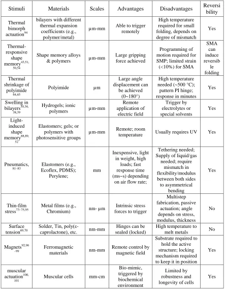
A theoretical study on bending behavior of bilayered laminates offers useful information for folding/bending, which is induced by mismatch in stress (or strain) between the two layers. Studying the bending curvature in bilayered systems offers a measure of the effect of stress (or strain) on system performance. The general theory of bilayer bending is derived from the model of a bi-metal strip as given by Timoshenko in 1925 (Figure 1.8).102 Here bending is assumed to take place in one direction only and the heating of the strip is assumed to be uniform. The bending curvature of the bilayer can be described by Equation (1.1).102
Figure 1.8. Schematics of bending of bi-metal strip.102 E1 and E2 are elastic moduli; α1 and α2 are thermal expansion coefficients for two layers separately; h1 and h2 are film thicknesses; and h is total thickness. P1 is tensile force for layer 1 and P2 is compressive force for layer 2.
( )( )( )
[ ( ) ( )( )] (1.1)
T. Equation (1.1) offers a guide to predict the bending curvature and impact parameters such as moduli, film thickness and temperature. However, Equation (1.1) only predicts uniform bending curvature and thus cannot predict the bending direction. Moreover, Equation (1.1) considers only elastic deformation so that it cannot be applied for viscoelastic polymers.
Recently, an analytical solution was introduced that predicts large deflections of circular or elliptical plates with lenticular cross-sectional shape when applying a temperature gradient across the film thickness.103,104 Self-rolling either from short side or long side has been demonstrated by controlling the ratio of length to width for a rectangular shape.105–107 For example, final rolling direction of epitaxially stressed InxGa1-xAs/GaAs rectangular films was found to depend on the dimension (length and width) of the original film as well as the tube circumference. Long-side rolling occurred with high aspect ratio of the film or larger tube circumference than film width.
These early studies on bending curvature are based on systems with small volume changes and low stress (or strain) gradients due to internal stress of materials, limited thermal expansion mismatch or ion compensation, which is not suitable for polymers or hydrogels involving high swelling ratio.
Thermal Transport Study
analysis based on lumped capacitance method has been applied to estimate the heat transfer between the solid and its surroundings to predict the temperature change within the solid as a function of time. Subsequent analysis assumes that the temperature gradient inside the solid is negligible, which is usually true for MEMS devices. The energy balance can be expressed using Equations (1.2-1.4) to describe the displacement of the cantilever:
( ) (1.2)
which gives the temperature profile:
( ) ( ) ( ) (1.3)
where
(1.4)
In the Equations (1.2) and (1.3), qh is power density, Ah is surface area being heated, h is convection coefficient for air, T∞ is temperature of air, ρ is density of the solid, V is the volume of the solid materials, c is the thermal capacitance of the solid, T is temperature of the solid at time t, RT is the resistance to convection and CT is the lumped thermal capacitance.
If thermal actuation is triggered by means of Joule-heating, the temperature of bimorph beams can be governed by basic heat transport incorporating the heat generated through current (assuming that convection and radiation contribute little to heat losses):109
(1.5)
In Equations (1.5-1.6), J is the current density, V is applied voltage, R is the resistance, A is cross section of the beam, L is the length of the wires for Joule-heating, ρ is resistivity, and k is thermal conductivity of the solid materials.
The method as introduced above, which applies Joule-heating on pre-strained polymer sheet to localize the thermal actuation, models the heat generation in the core region (i.e., polymer directly above the electrical trace) at a semi-infinite surface where the core region is at x = 0 and the margin extended away from the core is semi-infinite (x → ∞). In this manner the basic heat transport solution can be applied.50
Modeling of Shape Memory Polymer behavior
Because large and complex shape changes occur during pre-programming of SMPs, prediction of deformation history of SMPs is desired for optimization of property recovery.110 Constitutive models have been developed for thermally-activated SMPs based on thermo-mechanical properties of SMPs and fundamental understanding of structure-function relationships.110–112 Different constitutive models limited to small deformation in 1D,113 based on multiphasic materials (active phase and frozen phase),114 and 3D finite deformation110,112 are based on volume fraction and explicit phases (glassy and rubbery phases). Recently, a constitutive model based on structural and stress relaxation has been developed.115
1.3 Strategies of Converting 2D plane to 2D with Surface Topography
surface topographies. We discuss the most prominent materials and mechanisms to form surface topography responding inherently to the properties of the substrate. For example, we do not include lithography here.
1.3.1 Surface Topography via Buckles Formation
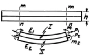
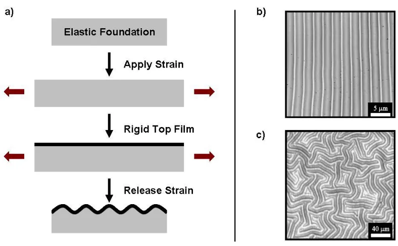
Figure 1.9. a) Schematic of the formation of buckles on an elastic substrate; b) optical microscopy images (top view) of typical unidirectional buckles and c) optical microscopy image of isotropic buckles (oriented in random directions).120
Although buckling is a spontaneous process, the attributes of the buckles are controllable to some extent. Assuming relatively small strains and an infinitely thick foundation, there is a well-developed model that predicts the wavelength (λ) and amplitude (A) of the buckles:
3 / 1 2 2 1 3 12
f s s f E E h (1.14) 2 / 1 1 c h A (1.15)
strain and εc is the critical value of ε.117,122
The wavelength based on an infinitely thick foundation is a function of materials’ properties (i.e., Young’s modulus and Poisson’s ratio) and the amplitude depends on the wavelength and the applied strain.
Although elastomers (e.g., PDMS) have been widely used as soft substrates in most studies featuring buckling/wrinkling, other materials such as polymers, hydrogels and polymer brushes can also be used to form buckles.
1.3.1.1 Mechanism for Buckles Formation Mechanical stretching
Buckles can form by mechanically stretching the elastic substrate. PDMS is used frequently as the elastic foundation due to its outstanding flexibility (Young’s modulus of ≈ 1 MPa) and stretching ability. 119,121 The skin can be manufactured by stiffening the surface of PDMS through oxidation by means of oxygen plasma or UV/Ozone (UVO) treatments, which transform the topmost regions of PDMS to a silica-like layer,119 or depositing metal or metal oxide (e.g., Au, Pt, ITO) on the pre-stretched elastomer substrate.118,123,124 Anisotropic buckles, i.e., arrangement of buckles in the direction perpendicular to the stretching direction, can be achieved after releasing uniaxially the mechanical strain, as shown in Figure 1.10.
cracks in the buckled topography; a fast strain release rate results in more defects, while a slow strain release rate generates numerous cracks.119
Atomic force microscopy (AFM) images of unidirectional buckles formed with by applying 50% strain are shown in Figure 1.10b, c. The aspect ratio, i.e., the ratio of the amplitude to the wavelength, of the buckles changed depending on the UVO dose, as shown in Table 1.2. The aspect ratio is a function of the materials’ properties, the thickness of top rigid layer and the applied strain. 118,119 The aspect ratio for buckles due to mechanical stretching is usually limited to ~0.2.119,121
Table 1.2. The aspect ratio of buckles resulting from different UVO doses. The applied axial strain is 50% for all samples, and the thickness of PDMS is ≈ 1 mm. The power density of UVO is 7.6 mW/cm2
UVO time (min) UVO dose (J/cm2) Wavelength (µm) Aspect ratio
45 20.6 ≈ 42 0.08-0.10
60 27.5 ≈ 48 0.12-0.16
75* 34.4 ≈ 60 0.17-0.26
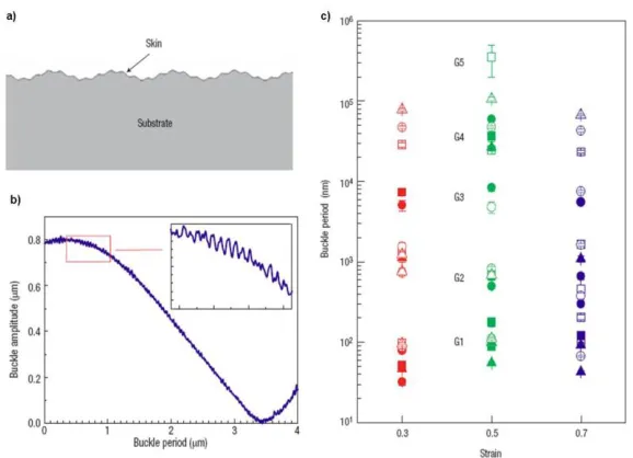
When a large strain is imposed, the resulting topography comprises hierarchically-structured buckles, where smaller buckles reside on top of larger ones (Figure 1.11a).117,119 Up to five generations of buckles (sizes ranging from nanometers to a fraction of a millimeter) have been detected by profilometry and scanning probe microscopy (Figure 1.11b, c).
Different metals can be deposited as a hard skin on the surface of pre-stretched elastomer sheets to form buckles upon releasing the strain from the sample. For example, Indium tin oxide (ITO) is used frequently in forming transparent electrodes in applications such as solar cells and flat panel displays for its optimal optical and electrical properties.124 In our experiments, an ITO film (40 nm) was deposited onto a pre-stretched PDMS sheet (1 mm, ε ≈ 10%) by sputtering. After ITO deposition, the strain was slowly released from the sample, which resulted in the formation of buckles.
The surface topography was studied by optical microscopy and a representative example is shown in Figure 1.12. The process exhibited a hysteretic behavior during the release-stretch cycle, as reported.123 The as-sputtered film, without releasing the strain, already contained buckles aligned parallel to the stretching direction. The formation of such buckles can be explained as follows. Due to the large thermal expansion coefficient of PDMS (≈ 96×10-5
Figure 1.12. Optical microscopy images of buckles formation when releasing and re-applying strain on an ITO sputtered PDMS sheet. The image was first taken right after ITO sputtering (ɛ ≈ 10%), more images were taken when slowly releasing the strain from 10% to 2%. The film was re-stretched after total release (ɛ ≈ 0%) to ɛ ≈ 10% and overstretched to ɛ ≈ 12%. The images were taken consecutively (scale bar: 20 µm for all images)
While elastomers, like PDMS, are popular as the substrates for buckle formation, generation of wrinkles by stretching other polymers (i.e., synthetic PET or rubbers) has also been demonstrated. 127
Thermal expansion
the polymer substrate is heated and expanded either by external heat source before the deposition of top film or by energy generated during the deposition, a compressive stress develops in the top film upon cooling that competes with the tensile stress in the polymer substrate and results in the formation of buckles in random direction (isotropic buckles) (Figure 1.9c).118,125
Besides generating isotropic buckles by utilizing thermal expansion through pre-heating the substrate before or during the deposition of top metal film, isotropic buckles can be also formed during annealing of metal (metal oxide)/polymer bilayer films deposited on flat rigid substrates.128,129 For example, buckles can be formed after heating bilayer films of Al/PS resting on silicon substrates.128 Here buckling takes place due to the mismatch of thermal expansion between the top capping film (Al, 25x10-6 K-1) and the bottom support (Si, 3x10⁻⁶ K-1). To test this hypothesis, by replacing Si with Zn as the support, no buckles are detected after heating the specimen, which can be explained by considering that the thermal expansion of Al and Zn is the same.
Other stress sources
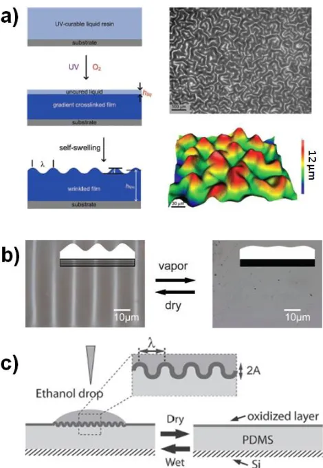
Figure 1.13. (a) Schemcatic, optical microscopy image and 3D profilometer image of isotropic buckles formed due to spontaneous swelling of a gradient crosslinked UV-curable resin (2-phenoxyethyl acrylate, crosslinker is 1,6-hexanediol diacrylate, photoinitiator is Irgacure 184). 130 (b) Optical microscopy images of ordered buckles on Polyacrylamide/NP-TiO2-CTAB PVP hybrid gel before and after water vapor treatment. (CTAB: cetyltrimethylammonium bromide; NP-TiO2: titania nanoparticles).131 (c) Schematic of reversible surface buckles of UVO-treated PDMS to oxidize the surface due to the swelling in response to different solvents.132
1.3.1.2 Applications
direct the cell growth,134 smart adhesive surfaces,135 optical devices such as microlenses and 136
diffraction gratings.122,125 Moreover, by making use of the buckling mechanism, buckled structures can be applied as a characterization tool to assess the modulus of materials employed as rigid thin layers.122 In addition, the application of buckled structures as light trapping surfaces has been explored.137–140 Hierarchical buckles are well-suited topographical structures that enhance trapping of light with various wavelengths since the buckle wavelengths range from micro- to the nano-scale.119 In contrast to previously fabricated light trapping structures (e.g., light-scattering reflector, V-shaped structure), buckled surfaces offer unprecedented means of tailoring topographies and sizes in a simple manner and are thus expected to be well-suited for fabrication of OPV devices that possess increased efficacy of light absorption. Buckling represents a simple fabrication method and does not require any complex processing steps beyond those already used to make planar devices.
We propose that a buckled substrate with corrugations and therefore improved light trapping provides a promising means of preparing high-efficiency OPV devices in a simple, low-cost manner. This will be further discussed in Chapter 6.
1.3.2 Surface Topography via Shape Memory Effect
and optical sensors. Moreover, the surface topography recovered of a shape memory polymer has shown a repeatable, strong and reversible dry adhesion to a glass substrate.12
Figure 1.14. Surface topography due to shape memory effect in an acrylate-based SMP (cured from methyl methacrylate (MMA), poly(ethylene glycol dimethacrylate) (PEGDMA) as crosslinker and 2,2-dimethoxy-2-phenylacetodphenone (initiator)). Schematics (top) and images (bottom) for different stages: (a) permanent pattern molded by thermally embossing nanoimprint lithography at ~180 °C; (b) 2D planar surface after programming with a flat mold; and (c) recovered surface topography after heating at ~120 °C. The pattern has a pitch of ~ 800 nm and a height of ~ 180 nm.141
1.3.3 Surface Topography via Polymer Brushes
Au-thiol bonds and so expansion in lateral direction. This can be applied in soft lithography stamping or in manufacture of nanofluidic channels.31
1.4 Summary and Dissertation Outline
In this review, we have introduced several fabrication strategies and stimuli mechanisms that can be used to convert 2D planar shape programmable polymeric materials to a 3D shapes, involving either out-of-plane bending or change of in-plane surface topography. Working with 2D sheets is attractive since these structures are compatible with many planar processes developed for semiconductor processing as well as many patterning techniques. In this Ph.D. dissertation we focus specifically on strategies that employ polymeric materials and thermal actuation to trigger self-folding of polymer sheets to generate 3D structures with various shapes and the formation of buckled surface topographies.
sheet. Because the strain relaxes in a gradual manner across the sheet thickness, the film folds in the inked region. We have study experimentally the influence of key process parameters and modeled the thermal transport phenomenon to achieve precise control of folding. Chapter 3 provides an insight into the kinetics of this self-folding process based on pre-strained polymer sheets. We correlate the macroscopic, thermally-driven shrinkage behavior of pre-strained polystyrene sheets to the kinetics of self-folding of these sheets. The macroscopic shrinkage of pre-strained polymer sheets as a function of temperature, time and heating rate provides information about the kinetics of shrinkage of the polymer within the dynamic thermal environment that the polymer sheets experience during folding. A simple geometric model that incorporates these macroscopic measurements predicts successfully the maximum bending angle as well as the kinetics of folding process in the ‘hinge’ (i.e., folding angle as a function of time). Different light (or heat) sources are capable programming self-folding of strained polymer sheets. Chapter 4 demonstrates rapid self-self-folding of pre-strained polymer sheets using focused laser light. This hinging response occurs even without pre-defined hinges on a compositionally homogeneous polymer sheet. Chapter 5 investigates self-folding by adopting different ink colors and utilizing light-emitting diodes (LEDs) with various emitting wavelengths, which is appealing to realize sequential folding for many applications such as reconfigurable devices and complicated origami folding.
References
1. Hawkes, E. et al. Programmable matter by folding. Proc. Natl. Acad. Sci. 107, 12441–12445 (2010).
2. Rashed Khan, M., Hayes, G. J., So, J.-H., Lazzi, G. & Dickey, M. D. A frequency shifting liquid metal antenna with pressure responsiveness. Appl. Phys. Lett. 99, 013501 (2011).
3. Cho, J.-H. et al. Nanoscale Origami for 3D Optics. Small 7, 1943–1948 (2011).
4. Bassik, N., Abebe, B. T., Laflin, K. E. & Gracias, D. H. Photolithographically patterned smart hydrogel based bilayer actuators. Polymer 51, 6093–6098 (2010).
5. Ilievski, F., Mazzeo, A. D., Shepherd, R. F., Chen, X. & Whitesides, G. M. Soft Robotics for Chemists. Angew. Chem. 123, 1930–1935 (2011).
6. Small, W., Wilson, T. S., Benett, W. J., Loge, J. M. & Maitland, D. J. Laser-activated shape memory polymer intravascular thrombectomy device. Opt Express 13, 8204– 8213 (2005).
7. Small, IV, W., Singhal, P., Wilson, T. S. & Maitland, D. J. Biomedical applications of thermally activated shape memory polymers. J. Mater. Chem. 20, 3356 (2010).
8. Kuribayashi, K. et al. Self-deployable origami stent grafts as a biomedical application of Ni-rich TiNi shape memory alloy foil. Mater Sci Eng -Struct Mater Prop
Microstruct Process 419, 131–137 (2006).
9. Henry, C. P., McKnight, G. P., Enke, A., Bortolin, R. & Joshi, S. 3D FEA simulation of segmented reinforcement variable stiffness composites</title> in (Dapino, M. J. & Ounaies, Z.) 69290X–69290X–12 (2008). doi:10.1117/12.778891
11. MorePhone: Revolutionary shape-changing phone curls upon a call (w/ Video). at
<http://phys.org/news/2013-04-morephone-revolutionary-shape-changing-video.html>
12. Eisenhaure, J. D., Xie, T., Varghese, S. & Kim, S. Microstructured Shape Memory Polymer Surfaces with Reversible Dry Adhesion. ACS Appl. Mater. Interfaces 5, 7714–7717 (2013).
13. Blewitt, M. J. & Willits, R. K. The Effect of Soluble Peptide Sequences on Neurite Extension on 2D Collagen Substrates and Within 3D Collagen Gels. Ann. Biomed. Eng. 35, 2159–2167 (2007).
14. Efimenko, K., Finlay, J., Callow, M. E., Callow, J. A. & Genzer, J. Development and Testing of Hierarchically Wrinkled Coatings for Marine Antifouling. ACS Appl.
Mater. Interfaces 1, 1031–1040 (2009).
15. Xu, H. et al. Deformable, Programmable, and Shape-Memorizing Micro-Optics. Adv.
Funct. Mater. 23, 3299–3306 (2013).
16. Strategic Polymer Sciences, Inc. - EMP Technology. at http://www.strategicpolymers.com/technology/>
17. Jaffe, B. Piezoelectric Ceramics. (Elsevier, 2012).
18. Pak, Y. E. Linear electro-elastic fracture mechanics of piezoelectric materials. Int. J.
Fract. 54, 79–100 (1992).
19. Wei, Z. G., Sandstroröm, R. & Miyazaki, S. Shape-memory materials and hybrid composites for smart systems: Part I Shape-memory materials. J. Mater. Sci. 33, 3743–3762 (1998).
20. Ambrosy, A. & Holdik, K. Piezoelectric PVDF films as ultrasonic transducers. J.
Phys. [E] 17, 856–859 (1984).
21. Shirinov, A. V. & Schomburg, W. K. Pressure sensor from a PVDF film. Sensors