ISSN(Online) : 2319 - 8753
ISSN (Print) : 2347 - 6710
International Journal of Innovative Research in Science,
Engineering and Technology
(An ISO 3297: 2007 Certified Organization)
Vol. 4, Issue 4, April 2015
Copyright to IJIRSET DOI: 10.15680/IJIRSET.2015.0404162 2273
Study of Heat Pipe Cooling in A Machining
Process
S.Nakkeeran,V.Ganesh Ram, Dr. J. Hameed Hussain
Asst.Professor, Department of Mechanical Engineering, Bharath University, ,Chennai,Tamilnadu,India
Teaching Fellow, Department of Rubber and Plastics Technology, Madras Institute of Technology, Chennai, India
Professor, Department of Mechanical Engineering, Bharath University,Selaiyur,Chennai,Tamilnadu,India
ABSTRACT: Tool wear of machine tools and large usage of cutting fluids is one of the major problems in manufacturing. Cutting fluids are used to cool down the tool and have been shown to cause environmental problems in machine shops. Tool life and temperature have an inverse relationship, namely that the higher the temperature at the tool-chip interface is, the lower the tool life
will be, and vice-versa. This paper investigates the performance of a cutting tool embedded with a heat pipe on reducing cutting
temperature and wear in machining. The temperature of a tool plays an important role in thermal distortion and the machined part‟s dimensional accuracy, as well as the tool life in machining. A new embedded heat pipe technology has been developed to effectively remove the heat generated at the tool–chip interface in machining, thereby, reducing tool wear and prolonging tool life. In particular, the technique can effectively minimize pollution and contamination of the environment caused by cutting fluids, and the health problems of skin exposure and particulate inhalation in manufacturing. Experiments should be carried out in both with and without heat pipe in machining and the temperature will be measured. The ANSYS finite element analysis should be carried out to determine the temperature near the cutting edge.
KEYWORDS-Dry machining. Tool design. Heat pipe. Heat transfer. Wear. Temperature
I. INTRODUCTION
ISSN(Online) : 2319 - 8753
ISSN (Print) : 2347 - 6710
International Journal of Innovative Research in Science,
Engineering and Technology
(An ISO 3297: 2007 Certified Organization)
Vol. 4, Issue 4, April 2015
Copyright to IJIRSET DOI: 10.15680/IJIRSET.2015.0404162 2274
contamination of the environment by cutting fluids and the health problems of skin exposure and particulate inhalation in manufacturing can be effectively minimized.
II. HEAT GENERATION IN MACHINING
In machining operations, mechanical work is converted to heat through the plastic deformation involved in chip formation and through friction between the tool and the work piece. Figure 2bshows the subsequent dissipation of that heat in the chip, tool, and the work piece. The heat generated during the metal cutting process where the work being done on the tool insert transforms itself in the form of heat. Consequently, the heat generation rate, Q (W), can be calculated based on the following formula
where d is the depth of cut (mm), f is the feed rate (mm/ rev), and V is the cutting speed (m/min).Heat is generated at the tool–chip interface in the quarter-circular area (heat source area) of the tool insert rake surface, and a portion of it flows into the tool, as shown in Fig. 2a.
Fig. 1 Heating of a tool carbide insert where a is the width of insert, b is the length of insert, c is the thickness of insert.
III. EMBEDDED HEAT PIPE IN A CUTTING TOOL IN MACHINING
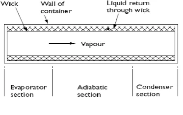
The main regions of the standard heat pipe are shown in Fig. 3a. The heat pipe is made up of an evaporator section and a condenser section. Should external geometrical requirements make this necessary, a further, adiabatic, section can be included to separate the evaporator and condenser. The heat pipe consists of the container wall, the wick structure and the vapour space.
Fig 2a Main regions of heat pipe
ISSN(Online) : 2319 - 8753
ISSN (Print) : 2347 - 6710
International Journal of Innovative Research in Science,
Engineering and Technology
(An ISO 3297: 2007 Certified Organization)
Vol. 4, Issue 4, April 2015
Copyright to IJIRSET DOI: 10.15680/IJIRSET.2015.0404162 2275
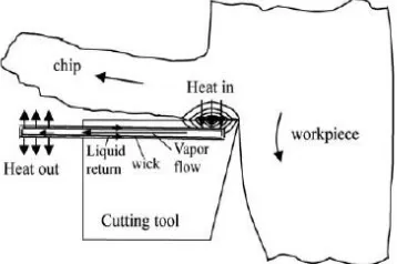
evaporation temperature of working fluid, the working fluid will be evaporated. That causes the pressure difference between evaporator section and condensation section, which allows the vapour to flow to the condensation section. In condensation section the heat will be taken out, because of that the vapour becomes fluid. This process will continue until the machining is stopped. Schematic illustration of an embedded heat pipe in a cutting tool in machining was shown in the fig 2b.
Fig 2b. Schematic illustration of an embedded heat pipe in a cutting tool in machining.
IV. EXPERIMENTS IN A CUTTING TOOL
An experimental study was undertaken on a conventional lathe using a commercially available brazed carbide tool. The work piece material was taken for the experiment is AISI 1020 carbon steel. The work piece was in the form of a 35 cm long cylindrical rod with a diameter of 70 mm. The standard tool manufactured by sandvik coromant with specification IS06 R2525 P30 was used for cutting experiments. The DARWIN data acquisition software 32 (DAQ 32) was used to measure the temperature in the tool continuously of 5 second interval for the machining distance of 22 cm length. Experiments were conducted for twocases such as with and without heat pipe. Two T-type thermocouples were affixed on the side of the carbide insert in order to measure the temperature in the carbide insert. The geometry and material properties of the tool and the heat pipe are given below
Heat pipe length 150 mm Heat pipe inner diameter 5.5mm Heat pipe outer diameter 6.5 mm Condenser length of heat pipe 50 mm
Tool holder size 25x25 mm
Carbide insert thickness 8 mm Carbide insert length 20 mm Carbide insert width 12 mm
The turning operation is controlled by varying the parameters like depth of cut, feed rate and cutting speed. For this present work we have taken two set of values for control the turning operation.
ISSN(Online) : 2319 - 8753
ISSN (Print) : 2347 - 6710
International Journal of Innovative Research in Science,
Engineering and Technology
(An ISO 3297: 2007 Certified Organization)
Vol. 4, Issue 4, April 2015
ISSN(Online) : 2319 - 8753
ISSN (Print) : 2347 - 6710
International Journal of Innovative Research in Science,
Engineering and Technology
(An ISO 3297: 2007 Certified Organization)
Vol. 4, Issue 4, April 2015
Copyright to IJIRSET DOI: 10.15680/IJIRSET.2015.0404162 2277
ISSN(Online) : 2319 - 8753
ISSN (Print) : 2347 - 6710
International Journal of Innovative Research in Science,
Engineering and Technology
(An ISO 3297: 2007 Certified Organization)
Vol. 4, Issue 4, April 2015
Copyright to IJIRSET DOI: 10.15680/IJIRSET.2015.0404162 2278
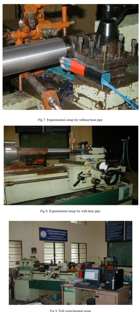
The experimental setup for with and without heat pipe was given in the following figure.
Fig 7. Experimental setup for without heat pipe
Fig 8. Experimental setup for with heat pipe
ISSN(Online) : 2319 - 8753
ISSN (Print) : 2347 - 6710
International Journal of Innovative Research in Science,
Engineering and Technology
(An ISO 3297: 2007 Certified Organization)
Vol. 4, Issue 4, April 2015
Copyright to IJIRSET DOI: 10.15680/IJIRSET.2015.0404162 2279
V. FINITE ELEMENT SIMULATION OF TURNING OPERATION
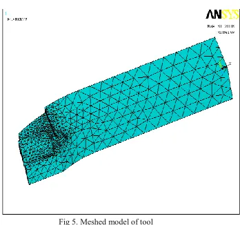
A finite element model (FEM) 3-D model in ANSYS was developed for the simulation of temperature based on the estimated machining heat flux over the tool–chip contact area on a tool insert of a cutting tool. The hear generation is calculated by the equation (Eqn 1) The temperature distribution is obtained from the balance of the heat generated and transient thermal analysis for two cases: without and with heat pipe cooling. The real geometry of the cutting tool is chosen as the computational domain. Figures 5shows the schematic meshed model of the finite element analysis (FEA) models of the cutting tool for the two cases of without and with heat pipe cooling. To achieve more realistic and accurate simulation results, the model takes into account the real geometry of the cutting tool and the thermal resistance. By using constant thermophysical properties, the 3-D transient heat conduction equation becomes:
where αT is the tool thermal diffusivity
Fig 5. Meshed model of tool
The heat converted from the work of plastic deformation and friction is assumed to be the same for the two cases in the simulations. A typical simulation is based on a constant time step of 40 s and a substep of 1 s for a cutting time of 400 s. To simulate the thermal resistance of the thermal grease, a layer of 0.1 mm in height is placed between the heat pipe and the tool insert. The effective thermal conductivity of the heat pipe is obtained from experiments. To simulate the heat pipe‟s thermal behavior, the convective heat transfer coefficients for the heat pipe‟s adiabatic section and condense section are set to 5 W/m2°C and 1,200 W/m2°C, respectively. The convective heat transfer coefficients for most surfaces on the tool holder are set to 10 W/m2°C, except the one for the back surface, which is set to 5 W/m2°C. Other convective heat transfer coefficients for the cutting tool top surface and the side surface are set to 20 W/m2°C and 15 W/m2°C, respectively, with the one for the shim seat set at 5 W/m2°C.
The geometry and material properties of the tool and the heat pipe are given below Heat pipe length 150 mm
Heat pipe inner diameter 5.5mm Heat pipe outer diameter 6.5 mm Condenser length of heat pipe 50 mm
ISSN(Online) : 2319 - 8753
ISSN (Print) : 2347 - 6710
International Journal of Innovative Research in Science,
Engineering and Technology
(An ISO 3297: 2007 Certified Organization)
Vol. 4, Issue 4, April 2015
Copyright to IJIRSET DOI: 10.15680/IJIRSET.2015.0404162 2280
VI. CONCLUSION
The heat transfer behaviour from an experimental model in the present study demonstrated that the heat generated in machining can be effectively removed by the use of a heat pipe installed on a cutting tool. The result based on the comparison between with heat pipe and without heat pipe in dry machining shows that the feasibility of the concept of using a heat pipe for reducing heat and cutting fluids in machining.
REFERENCES
1. Peterson, G.P., 1994. An Introduction to Heat Pipes. Canada: John Wiley & Sons, Inc.Petrucci,
2. Kumar S., Das M.P., Jeyanthi Rebecca L., Sharmila S., "Isolation and identification of LDPE degrading fungi from municipal solid waste", Journal of Chemical and Pharmaceutical Research, ISSN : 0975 – 7384 5(3) (2013) pp.78-81.
3. R.H.,Harwood,W.S.,Herring,G.General “Chemisty Principles and Modern Applications.”2001,Prentice-Hall,Inc., Mar06.
4. Sundar Raj M., Arkin V.H., Adalarasu, Jagannath M., "Nanocomposites based on polymer and hydroxyapatite for drug delivery application", Indian Journal of Science and Technology, ISSN : 0974-6846, 6(S5) (2013) pp.4653-4658.
5. Puneet Tandon P. Gupta S. G. Dhande “Geometric modeling of single point cutting tool surfaces” Int J Adv Manuf Technol (2003) 22: 101– 111
6. Vijayaprakash S., Langeswaran K., Gowtham Kumar S., Revathy R., Balasubramanian M.P., "Nephro-protective significance of kaempferol on mercuric chloride induced toxicity in Wistar albino rats", Biomedicine and Aging Pathology, ISSN : 2210-5220, 3(3) (2013) pp.119-124. 7. Richard Y. Chiou, Vitaliy Aynbinder, L. G. Stepanskiy, Lin Lu, and Shreepud Rauniar,” Analytical Study of the Effect of Heat Pipe Cooling in
Machining”, Proceedings of IMECE 2005 ASME November 5-11, 2005, Orlando, FL
8. Sundararajan M., "Optical instrument for correlative analysis of human ECG and breathing signal", International Journal of Biomedical Engineering and Technology, ISSN : 0976 - 2965, 6(4) (2011) pp.350-362.
9. Murase, T., Yoshida, K., Koizumi, T., and Ishida, N., 1982, “Heat Pipe Heat Sink „Heat Kicker‟ for Cooling of Semi-Conductors,” Furukama Review, Japan, Vol.2, pp24-33.
10. Laljee R.P., Muddaiah S., Salagundi B., Cariappa P.M., Indra A.S., Sanjay V., Ramanathan A., "Interferon stimulated gene - ISG15 is a potential diagnostic biomarker in oral squamous cell carcinomas", Asian Pacific Journal of Cancer Prevention, ISSN : 1513-7368, 14(2) (2013) pp.1147-1150.
11. P Thamarai, B Karthik, Automatic Braking and Evasive Steering for Active Pedestrian Safety, Middle-East Journal of Scientific Research 20 (10), PP 1271-1276, 2014.
12. M.Bharathi, Golden Kumar,Design Approach For Pitch Axis Stabilization of 3-Dof Helicopter System an LQR Controller,International Journal of Advanced Research in Electrical, Electronics and Instrumentation Engineering,ISSN 2278 - 8875 , pp 351-365 ,Vol. 1, Issue 5, November 2012.
13. SRIDHAR RAJA. D ,Foliated UC-EBG UWB Bandpass filter ,International Journal of Advanced Research in Electrical, Electronics and Instrumentation Engineering ,ISSN (Print) : 2320 – 3765,pp 3701-3708,Vol. 2, Issue 8, August 2013.
14. V.M. Ramaa Priyaa,Predictive Control in Power Converters,International Journal of Advanced Research in Electrical, Electronics and Instrumentation Engineering, ISSN (Print) : 2320 – 3765 , pp 10475-10478 ,Vol. 3, Issue 7, July 2014.
15. Vijayan T ,Performance of Microstrip Directional Coupler Using Synthesis Technique,International Journal of Advanced Research in Electrical, Electronics and Instrumentation Engineering, ISSN: 2278 – 8875, pp 761-767,Vol. 2, Issue 3, March 2013.