Transactions of the 17th International Conference on Structural Mechanics in Reactor Technology (SMiRT 17) Prague, Czech Republic, August 17 –22, 2003
Paper # C03-3
Scenario for the Damage of PWR Fuel Cladding in Situations of Pellet-Cladding
Interaction
Gilles Rousselier1), Sylvain Leclercq1), Olivier Diard1)
1) EDF R&D, Materials and Mechanics Dept. MMC, Les Renardières, F-77818 Moret-sur-Loing, France
ABSTRACT
On the basis of existing experimental data, mainly from power transients experiments on irradiated fuel, and of finite element calculations of these experiments, a linear elastic fracture mechanics analysis with a crack arrest
criterion has been performed. It gives the main characteristics of intergranular and transgranular cracking of cladding tubes.
KEY WORDS: nuclear, fuel rod, cladding, power transients, pellet-cladding interaction, damage, stress, stress-corrosion, cracking, intergranular, transgranular, crack growth, crack arrest, stress intensity factor, Zircaloy-4,
INTRODUCTION
Nearly 80 percent of French electric power has a nuclear origin, generated by 58 pressurized water reactors (PWR). The production adaptability to the network demand brings about more severe mechanical loadings of the cladding. In particular, it has to be assessed that power transients do not produce excessive damage of the cladding in situations of pellet-cladding mechanical interaction (PCMI).
In PWRs, under steady-state operating conditions, the initial gap existing between the fuel pellets and the cladding closes. After about 10 000 hours of operation, this “strong” PCMI induces high tensile stresses in the cladding when a transient occurs. The transient also induces the release of corrosive fission products in the radial cracks of the pellet, leading to stress-corrosion cracking (SCC) of the cladding in front of the cracks [1]. The PCMI/SCC damage of the cladding has a striking feature: depending for example on the maximum power of the fuel rod, either a through-crack is obtained after ten minutes or less, or the SCC damage is limited to a few microns, even after hours at the maximum power. This discontinuous behaviour is obtained above the SCC initiation threshold, and therefore cannot be explained by this threshold effect. In this paper, a scenario is proposed to explain this particular feature.
Some experimental information and data on PCMI/SCC damage of Zircaloy-4 cladding are given in the first section. In section 2, the methodology is presented with quantitative results that support the proposed scenario. The limitations of the analysis and prospects are discussed in section 3.
EXPERIMENTAL INFORMATION AND DATA
At the very beginning of its life in the reactor, after a power increase, the fuel pellet fractures. The high temperature gradient in the pellet leads to hourglassing. The pellet also swells under irradiation. The cladding creeps towards the interior under the action of the differential pressure: pressure of the primary water circuit (about 15 MPa) minus the initial internal pressure in the rod (about 6 MPa in hot conditions). Due to hourglassing, the pellet and the cladding first contact at the inter-pellet planes, creating primary ridges at the cladding exterior surface.
The phenomena occurring during transients can be observed in experimental reactors. During an experimental power ramp simulating a transient, the power increase (typically 100 W/cm/min, for example from 200 W/cm to 400 W/cm) is followed by a plateau of an hour or more at the maximum power. The stresses increase dramatically at the intersection of radial cracks planes and inter-pellet planes with the inner surface of the cladding (triple points). During the power ramp, the release of volatile and corrosive fission products (mainly iodine) accelerates in front of the radial cracks in the pellet. The chemical activity of these products is sufficient to develop SCC in the cladding [1].
The morphology of SCC surfaces in Zircaloy-4 has characteristic aspects of cracking and deformation mechanisms of hexagonal close-packed metals. The vicinities of crack initiation zones are exclusively intergranular. In experimental or power reactors, the intergranular crack can range from a few to 10 or 20 µm. The rest of the cracking surfaces are purely transgranular, a mixture of quasi-cleavage on the basal planes of zirconium and connexion of these planes by plastic deformation (flutting). The quasi-cleavage is enhanced by irradiation hardening that increases the stresses and adsorption of corrosive fission products that lowers the surface energy of the basal planes. This explains the limited amount of intergranular crack propagation in the irradiated material.
Intergranular cracks initiate above some stress level, in the order of 300 MPa [2]. Laboratory experiments on pre-cracked tubes give a good estimate of the transgranular crack propagation rate: da/dt = Vtrans ranges from 0.3 to 3 µm/s
in irradiated Zircaloy-4 at 350°C. The mean value Vtrans= 1 µm/s will be used in the paper. The intergranular rate Vinter
transition from intergranular to transgranular SCC is supposed to occur for a critical stress intensity factor Ktransin the
order of 3 MPa√m for the unirradiated material. It decreases with radiation damage [1].
At 320°C and at higher temperatures, stress-relieved Zircaloy-4 presents a viscoplastic stress-strain behavior, including in the irradiated state [4,5,6]. Stress relaxation during the power plateau has thus to be taken into account. Another important factor is the stress profile through the cladding. As a matter of fact, the stress gradients are very steep at the triple points. 2D finite element (FE) calculations of the fuel rod were performed for a power increase from 200 W/cm to 400 W/cm at 100 W/cm/min, with four radial cracks in the pellet [7]. Unified anisotropic viscoplastic constitutive relations were used for the stress-relieved Zircaloy-4 cladding at 350 °C [4,5,6]. The finite element size is close to 1 µm at the triple point. The stress profile is given in Fig. 1 for a friction coefficient f = 0.8. The stress decrease is very important in the first 10 to 20 µm from the inner surface. The maximum stress is strongly dependent on the friction coefficient, but the same features remain for other values of f. These results are confirmed by 3D calculations [8]. The stress relaxation does not exceed 50 MPa during the first 200 s of the power plateau.
Fig. 1 Stress profile through the cladding for a friction
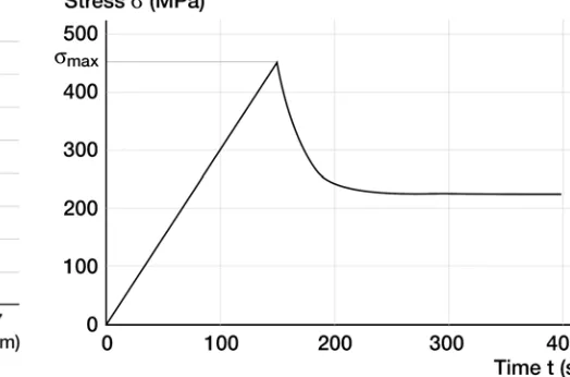
coefficient f = 0.8. 2D finite element calculation [7] Fig. 2 Postulated stress vs. time curve in the vicinity ofthe inner surface of the cladding (σmax = 450 MPa)
METHODOLOGY AND RESULTS
It is generally accepted that stress relaxation explains the small amount of SCC damage observed in experimental power ramps with maximum power smaller than a certain threshold, about 420 W/cm for a power variation of 100 W/cm/min and a steady-state level of 250 W/cm [1]. But at least at 350°C and for strain rates during the power increase smaller than 5.10-5s-1, the stress relaxation is not sufficient in a few minutes to explain that phenomenon. The
main factor is that the propagating crack goes out of the stress concentration zone of Fig. 1, in a few minutes if
Vinter = 0.1 µm/s. The stress “applied to the crack” decreases accordingly. That is why we have postulated stress versus
time curves as shown in Fig. 2. During power increase, we assume a linear increase of stress with time: σ = bt, with
b = 3 MPa/s. At σ = σmaxbegins the power plateau. The equation for the “stress applied to the crack” is then:
(
)
−
−
−
+
=
b
t
c
m
m
maxmax
1
exp
σ
σ
σ
(1)The parameter m = 0.5 is used in the calculations. The decrease of σ is first due to stress relaxation, then to the crack going out of the stress concentration zone. This is modelled with the parameter c = 0.05 s-1. The shape of the curve
should depend on σmax. But the faster stress relaxation of “physical” stresses at high stress levels is compensated by a less steep stress gradient, due to increased plasticity. The shape of Fig. 2 is thus considered as realistic. The curve depends on the single parameter σmax.
The crack initiates at a time t0. With t0 = 100 s, it corresponds to σ0 = 300 MPa, as in [2]. Once a crack is initiated,
discontinuity of the phenomenon above some threshold of the maximum stress. But crack arrest is not straightforward. We use a linear elastic fracture mechanics (LEFM) approach, with KI = 1.1σ√(πa) for a surface crack. If crack
initiation occurs after the maximum stress, the applied stress post-peak decrease of Fig. 1 is not steep enough to induce a decrease of the stress intensity factor, see Fig. 3. It is postulated that crack arrests when the two following conditions are met:
Ia
I
K
K
≤
,≤
0
dt
dK
(2)
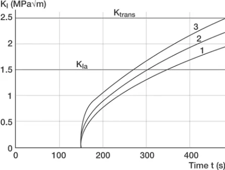
In order to compensate the strong increase of KI from a = 0 due to √a , it is necessary that crack initiation take place
before the maximum stress. In Fig. 4, we have taken KIa = 1.5 MPa√m and Ktrans = 2.5 MPa√m. For σmax < 410 MPa,
we have KImax < KIa , and the crack stops at the maximum as the conditions (2) are met. For
410 MPa < σmax < 450 MPa, the conditions (2) are met after some crack propagation at decreasing stress intensity factor. For 450 MPa < σmax< 500 MPa, the crack propagates in the intergranular mode, until Ktrans is met, then it turns
to transgranular. For σmax > 500 MPa, the transgranular mode is obtained earlier, as the stress level during the power increase is sufficient to induce the quasi-cleavage.
Fig. 3 Stress intensity factor vs. time with the assumption of crack initiation after the beginning of the power plateau. Stress decrease (Fig. 2) has a limited effect on the curves (t0 = 150 s, 1: σmax =
350 MPa, 2: σmax = 400 MPa, 3: σmax = 450 MPa)
Fig. 4 Stress intensity factor vs. time with the assumption of crack initiation before the beginning of the power plateau (t0 = 100 s, 1: σmax = 420 MPa,
2: σmax = 450 MPa, 3: σmax = 500 MPa, □ crack
initiation, o crack arrest, • transition from intergranular
to transgranular cracking)
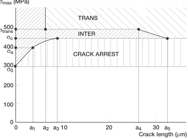
The stress intensity factor is given as a function of crack length in Fig. 5. The fracture behavior of the cladding can be deduced as a function of σmax in Fig. 6. For σmax < σ0 = 300 MPa, there is no SCC damage. σa ≈ 410 MPa is the
value of the maximum stress above which KIa is exceeded. For σmax < σc ≈ 450 MPa, the crack growth is purely
intergranular and smaller than a3 ≈ 10 µm, and the crack arrests. σc is the critical stress, as far as the integrity of the
cladding is concerned. The discontinuity in the macroscopic behavior of the fuel rod corresponds to σc. For
450 MPa < σmax< 500 MPa, the intergranular crack propagation is about 30 µm, and is followed by complete failure of
the cladding in 15 minutes after the beginning of the power ramp, by transgranular crack propagation. The instability of the remaining uncracked ligament, by ductile fracture, reduces the time to about 10 minutes or less. For
σmax > σtrans ≈ 500 MPa, the intergranular crack does not exceed 6 µm, and the cladding fails in 12 minutes, reduced
by the ligament instability. These results are in agreement with the power ramps experiments on Zircaloy-4.
Another discontinuity, at the microscopic scale, is the amount of intergranular crack propagation. It belongs to two separate intervals: [0, a3] if σmax < σc or σmax > σtrans, and [a4, a5] if σc < σmax < σtrans (see Fig. 6). These intervals
depend on the respective values of KIa and Ktrans. It would be interesting to check this prediction with experimental
Fig. 5 Stress intensity factor vs. crack length (1: σmax = 420 MPa, 2: σmax = 450 MPa, 3: σmax = 500 MPa)
a1 to a5: intergranular crack propagation before crack arrest or transition to transgranular cracking
DISCUSSION AND PROSPECTS
The results are not very sensitive to the value of Ktrans, as far as Ktrans > KIa. For Ktrans < 2 MPa√m, so that σtrans < σc, the second interval [a4, a5] disappears. KIa is the most important parameter for PCMI/SCC damage and
failure. For a given initiation stress σ0 the critical stress σc is determined by KIa. Different values of the crack
propagation rates would change the time to failure, but not the proposed scenario.
The postulated stress vs. time curve (Fig. 2) is very important too. Recrystallized Zircaloy is more viscoplastic during the power increase than stress-relieved Zircaloy-4. Consequently, the curve will present a plateau at some limiting stress, and the failure criterion σmax > σc is no longer effective. It can be replaced by some integral, like the
strain energy density
∫
σ
(
t
)
d
ε
p . Even in this situation, the proposed scenario remains valid, as the decrease of the “stress applied to the crack” is due mainly to the crack leaving the stress concentration zone at the triple point of the cladding. Anyway, the validity of these macroscopic failure criteria is questionable. The critical stress σc should dependon the irradiation and loading history. The macroscopic failure criterion has to be considered as an engineering criterion, based on experimental power ramps, with a safety margin including the uncertainties in the real failure criterion.
The analysis could be improved by applying calculated stress profiles σ(x,t) to the crack in a semi-infinite plane, instead of the formula KI = 1.1σ√(πa). The profiles are given by FE calculations of the fuel rod [7]. At the best, the fuel
rod could be calculated with a growing crack in the cladding, but this would be rather complicated and time consuming in a parametric study. Anyway, the main limitation of the analysis is the use of LEFM and global criteria like KI < KIa.
The problem is the same as for the initiation and propagation of a fatigue crack from a stress concentration zone. This zone is plastic or viscoplastic , and LEFM should not apply without corrections. Moreover, the conventional plastic zone size at the crack tip is
rp
= (1/6π)(KIa/σy)2, where σy is the yield stress of the cladding.rp
is in the order of 1 µm,not to be neglected as compared to the crack length in the first stage of crack growth after initiation.
Crack closure when the applied stress decreases is probably the main factor for crack arrest. It takes place at the microscopic scale, and it is doubtful that the global criterion KI < KIa give an intrinsic description of that phenomenon.
Moreover, the measure of KIa would be very difficult in representative conditions of the fuel rod in reactors.
At the scales considered here for crack arrest, from 1 to 20 µm, the metal is not homogeneous. The grain size is in the order of a few microns, in recrystallized as well as in stress-relieved Zircaloy. For this reason, a crystalline approach is recommended. Some realistic microstructures of the triple point zone are meshed including morphological information and local orientations of the lattice [7,8]. The single crystal viscoplastic model is described in [9], and values of the coefficients are reported in [10]. The FE mesh enables to take into account grain boundaries as volumic elements with specific constitutive relations. Furthermore the effect of corrosive fission products on the intergranular damage can be introduced by coupling a diffusion problem with a mechanical problem. With the stress and strain fields given by FE calculations of the fuel rod, we get a sophisticated tool to study PCMI/SCC. Preliminary results are given in Fig. 7 and 8 [8]. The main limitations are the computation time and the unknown physical data used as input.
Fig. 7 FE mesh of the polycrystalline aggregate.
Transactions of the 17th International Conference on Structural Mechanics in Reactor Technology (SMiRT 17) Prague, Czech Republic, August 17 –22, 2003
Paper # C03-3
CONCLUSION
During a power transient, the fuel rod can fail by a combination of pellet-cladding mechanical interaction and stress-corrosion cracking initiation and propagation (PCMI/SCC). In experimental power ramps with maximum power smaller than some threshold, typically 420 W/cm for a power variation of 100 W/cm/min and a steady-state level of 250 W/cm, the SCC damage is limited to a few microns of intergranular crack propagation, even after one hour or more at the maximum power. Above that threshold, the cladding tube fails completely in less than 10 minutes.
A scenario is proposed to explain this discontinuous behaviour. Crack propagation initiates before the maximum power is achieved, and the stress applied to the crack decreases from the beginning of the power plateau. The stress decrease is due to both stress relaxation in stress-relieved Zircaloy-4 alloy and the crack going out of the stress concentration zone at the point of strong pellet-cladding contact. A linear elastic fracture mechanics (LEFM) analysis is used, and the crack is supposed to arrest when both conditions KI < KIa and dK/dt < 0 are met. The results are in
qualitative and quantitative agreement with the power ramps experiments on Zircaloy-4.
Nevertheless, the use of LEFM and of KIa is questionable. The maximum stress criterion σmax > σc cannot be
extrapolated to different irradiation and loading histories. The analysis could be improved with finite element computations of the fuel rod coupled with a detailed calculation of the stress concentration zone. At the scale of this zone, about 20 µm, the metal is not homogeneous. A crystalline approach is all the more recommended because the damage is intergranular. With this approach, some progress is expected on crack arrest in various conditions and on the failure criterion of the fuel rod.
REFERENCES
1. Bailly, H., Ménessier, D. and Prunier, C., The Nuclear Fuel of PWR Reactors and Fast Reactors, Lavoisier Publishing, Paris, 1999.
2. Schuster, I. and Lemaignan, C., "Influence of Texture on Iodine-induced Stress Corrosion Cracking of Zircaloy-4 Cladding Tubes", J. Nucl. Mater., Vol. 189, 1992, pp. 157-166
3. Fandeur, O., “Etude Expérimentale et Modélisation de la Corrosion Sous Contrainte des Gaines en Zircaloy-4”, PhD thesis, Ecole Centrale de Paris, 2001.
4. Delobelle, P., Robinet, P. and Geyer, P., “A Model to Describe the Anisotropic Viscoplastic Behaviour of Zircaloy-4 Tubes”, J. Nucl. Mater., Vol. 238, 1996, pp. 135-162.
5. Schäffler, I., Geyer, P., Bouffioux, P. and Delobelle, P., “Thermomechanical Behaviour and Modelling Between 350°C and 400°C of Zircaloy-4 Cladding Tubes from an Unirradiated State to High Fluence”, J. Eng. Mater. and Techn., Vol. 122, 2000, pp. 168-176.
6. Richard, F., Delobelle, P., Leclercq, S., Bouffioux, P. and Rousselier, G., “Modelling of the Cold Work Stress Relieved Zircaloy-4 Cladding Tubes Mechanical Behavior under PWR Operating Conditions”, Proc. of the 17th International Conference on Structural Mechanics in Reactor Technology, paper C391, Prague, Czech Republic, August 17-22, 2003.
7. Diard, O., Leclercq, S., Rousselier, G. and Cailletaud, G., “Modeling of Intergranular and Transgranular Damage in Zircaloy Tubes”, pp.159-166, Continuous Damage and Fracture, A. Benallal ed., Elsevier, Paris, 2000.
8. Diard, O., “Un Exemple de Couplage Comportement-Endommagement-Environnement dans les Polycristaux, Application à l’Interaction Pastille-Gaine”, PhD thesis, Ecole des Mines de Paris, 2001.
9. Cailletaud, G., “Une Approche Micromécanique Phénoménologique du Comportement Inélastique des Métaux”, PhD thesis, Université Pierre et Marie Curie - Paris 6, 1987.