Broadband Capacitive Coupled Microstrip
Antenna with I-shape Slot for Wireless
Communication System
Ratnesh Dwivedi1, Prashant Purohit2
PG Student, Dept.of Electronics & Communication Engineering, Radha Raman Institute of Technology and Science, Bhopal, M.P., India1
Assoc. Prof., Dept. of Electronics & Communication Engineering, Radha Raman Institute of Technology and Science,Bhopal,M.P., India2
Abstract: In this paper capacitive fed rectangular patch Microstrip antenna loaded with I-shape slots is developed. The model of Antenna uses the capacitive feed strip which is fed by coaxial probe using equivalent circuit approach. The proposed antenna has the impedance bandwidth of 58% in the frequency range 3.9GHz to 7.14GHz which shows wideband characteristics. Gain is almost constant in the entire band of operation. The proposed antenna is simulated using IE3D software. It is shown that the antenna can cover the bands of several applications including WLAN, Satellite communication, Marine communication and terrestrial microwave links.
Keywords: Microstrip Antenna, capacitive coupling, wideband, slot.
I. INTRODUCTION
A Microstrip antenna is attractive candidate in the variety of commercial scale application such as mobile and spacecraft application due to their numerous advantages such as low cost, light weight and easily printed onto circuit board. However Microstrip antennas suffer from low bandwidth characteristics [1].Many efforts have been devoted to bandwidth widening techniques of Microstrip antennas, including the use of impedance matching [2], multiple resonators [3], and a thick substrate [4]. The simplest technique to overcome the size problem is to incorporate high dielectric constant substrate which is very expensive so it is not suitable in many applications [5]. The other technique using short circuit [6] or a short pin [7] has also been proposed. Much attention is focused to improve the bandwidth of short-circuited patch antennas [8-10].18.5% impedance bandwidth was obtained using thick foam as substrate [10].Two stacked short circuited patch were used to obtain impedance bandwidth of 30%[9].Using an L-probe feed substrate the impedance bandwidth obtained was more than 39% [10].Thus stacked and L-probe feed both increase the complexity of the antenna. In case of using high dielectric substrate the inductance introduced by coaxial probe will increase the height of foam which in turn limits the bandwidth improvement of the antenna. The U-slot cut on the patch proposed [11] can be used to cancel the inductance.
A single layer coplanar capacitive fed wideband Microstrip antenna is easy to fabricate and reported 28% impedance bandwidth [12] could be enhance by optimizing the feed strip dimensions and its position with respect to radiator patch [13].The probe inductance is compensated by placing capacitive feed strip along one side of radiator patch. The input impedance of Microstrip antenna is a key factor for matching between transmission line and antenna terminal. For impedance calculation various models like transmission line model, cavity model, moment method solution and equivalent circuit are used in which the equivalent circuit model [14], is simple and reasonably accurate but they consider that the probe feed is directly connected to radiator patch.
7.14GHz which shows the wideband behaviour. The antenna is useful for wideband applications including, RADAR communication, Marine communication, Satellite communication, WLAN and terrestrial microwave links.
.
II. ANTENNAGEOMETRYANDDESIGN
Fig.2. Equivalent circuit of probe with feed strip
In present geometry of antenna the feed is not given by directly connecting the coaxial probe, but the radiator patch is connected to a small rectangular patch which excites it capacitive coupling. The feed strip is equivalent to rectangular Microstrip capacitor because the dimension of the feed strip is much smaller in comparison to wavelength of operation. Since the area of the strip is very small as compared to patch,the perimeter to area ratio is much larger hence the fringing capacitance from the edges may be significant in this case. This capacitance is known as terminal capacitance of the line.
The dissipation and radiation losses from feed strip line can be represented as R strip. At lower frequency radiation losses from feed strip line are negligible but as the operating frequency increases, the radiation losses are effective. The separation between radiator patch and the feed strip is essentially an asymmetrical gap that means two conductors of unequal width separated by short distance (d).This can be represented by model of Cp1, Cs, and Cp2. Here Cp1 and Cp2 represent terminal capacitance of two Microstrip sections and the series capacitance Cs represents gap [13] and equivalent circuit of feed strip is shown in figure 2.
Fig.3. Circuit model of Antenna without slot
The input impedance of antenna without slot as shown in fig.3 can be calculated from equation (1)
Zin= + + +
Fig.4. Equivalent Circuit of I-shape slot loaded capacitive coupled Microstrip antenna
The complete equivalent circuit of the proposed antenna is shown in figure 4 and input impedance of the complete circuit can be calculated from equation (2).
Ztotal= . (2)
III.RESULTSANDDISCUSSIONS
The results of the proposed antenna were obtained by simulation using the IE3D software which is a method of moments (MoM) based electromagnetic software.Fig.5shows variation of return loss with frequency. The -10 dB return loss is between the frequency range 3.90GHz to 7.14GHz.The center frequency of this proposed design is 5.52GHz and the impedance bandwidth is 58% which shows that the antenna exhibits broadband characteristics.
The gain variation with is shown in figure 8. The variation of gain is less than 1dB. The radiation patterns at frequencies 3.9GHz, 5.52GHz and 7.14 GHz are shown in figure 9(a), 9(b), 9(c).The patterns shows that H plane patterns are symmetrical throughout the band of operation whereas E plane patterns are symmetrical at lower and higher frequencies and as the frequency approaches to center frequency, the degree of asymmetry increases.
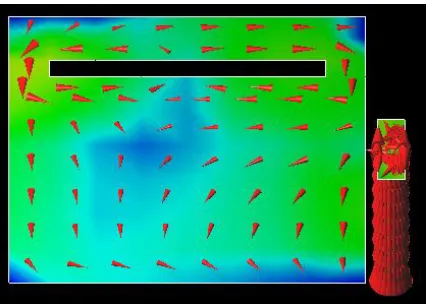
Fig. 7(a) Surface current distribution at 3.9GHz Fig.7 (b) Surface current distribution at 5.52GHz
Fig.9 (a) Radiation Pattern at frequency 3.9GHz
IV. CONCLUSION
In this communication, I-shape slot loaded capacitive coupled patch antenna with broad band behaviourhas been presented. The impedance bandwidth of 58% has been achieved. This antenna can be used for wireless communication system. The proposed antenna also operates in 5GHz band hence can be used for WLAN application. The antenna can cover the bands of several applications including WLAN, Satellite communication, Marine communication and terrestrial microwave links.
REFERENCES
[1] Garg, R.,P.Bhartia, I.Bahl and A. Ittipiboon, Microstrip antenna design handbook, Artech house, Boston, London, 2003.
[2] H. F. Pues and A. R. Van De Capelle, “An impedance matching technique for increasing the bandwidth of microstrip antenna,” IEEE
trans. Antenna and Prop. 37, pp. 1345-1354, 1989.
[3] R. Q. Lee, K. F. Lee and J. Bobinchak, “Characteristic of a two layer electro-magnetically coupled rectangular patch antenna,” Electron
Letters, 23, pp. 1070-1072, 1987.
[4] E. Chang, S. A. long and W. F. Richard, “Experimental investigation of electrically thick rectangular microstrip antennas,” IEEE Trans.
Antenna and Prop. 34, pp. 767-772, 1986.
[5] T. K. Lo,C.O, Ho,Y.Hwang,E. K. W.Lam,and .Lee,Miniature aperture-coupled Microstrip antennaof very high permittivity,Electron Lett
33,pp. 9-10,1997.
[6] S. Pinhas and S. Shtrikman,“Comparison between computed and measured bandwidth of quarter–wave microstrip radiators”,IEEE Trans
Antennas Propagat.,Vol. 36,pp. 1615-1616, 1988.
[7] R.B. Waterhouse, S.D. Targonski, and D.M.Koktoff,“Design and performance of small printed antennas”,IEEE Trans Antennas
Propogat.Vol.46, pp. 1629-1633,1988.
[8] R. Chair, K.F.Lee, K.M.Luk, “Bandwidth and cross- polarization characteristics of quarter-wave shorted patch”, Microwave and Optical
Technology Letters, vol.29, pp.101-103, 1999.
[9] L. Zaid, G.Kossiavas,J.Y. Dauvignac, J. Cazajous, and A. Papiernik, Dual frequency and broadband Antennas with stacked quarter
wavelength elements, IEEE Trans Antennas Propogat. 47, pp.654-660, 1999.
[10] Y.X. Guo,K.M.Luk, and K.F. Lee, “L- probe proximity-fed short-circuited patch antennas”, Electron Lett. Vol. 35, pp. 2069-2070,1999.
[11] T. Huynh and K.F.Lee,“Single -layer single-patch wideband Microstrip antenna”, Electron Lett.31, pp. 1310-1312, 1995.
[12] G. Mayhew-Ridgers, J. W.Odondaal, and J. Joubert, “Single-layer capacitive feed for wideband probe-fed microstrip antenna
elements,”IEEE Trans. Antennas Propag., vol. 51, pp. 1405–1407, 2003.
[13] Veeresh G Kasabegoudar and K.J.Vinay,“Coplanar capacitively coupled probe fed microstrip Antennas for wideband applications”, IEEE
Trans. Antennas Propag., vol. 58, pp. 3131–3138, 2010.
[14] V. K. Pandey and B. R. Vishvakarma, “Analysis of an E-shaped patch antenna,” Microw. Opt. Technol. Lett., vol. 49, no. 1, pp. 4–7,
2007.