Evaluation of Effect of In-Wheel Electric
Motors Mass on the Active Suspension System
Performance Using Linear Quadratic
Regulator Control Method
Abdussalam Ali Ahmed Omar
1, Başar Özkan
2Student at the Institute of Natural Sciences, Okan University, Istanbul, Turkey1
Associate Professor, Department of Mechanical Engineering,, Okan university, Istanbul, Turkey2
ABSTRACT:This paper presents evaluation of effect of in-wheel electric motors mass on the performance of active suspension system by using one of more common control methods which is Linear Quadratic Regulator (LQR).Unsprung mass is one of the important parameters which effects on road holding and ride comfort behaviors in the vehicles, this effect obtained in this work by comparing the performance of the system using standard tire and tire with In-Wheel Electric Motor. Also,modeling and simulation of quarter car model completed to construct the Simulink model of the system using MATLAB software. The study summarized bad effect of increasing the weight of tires by add In-Wheel Motors to the system on the road traction and the vehicles drivers comfort, at the same time the suspension system with wheel motor needs high actuator force to work compared to the same system without in-wheel motor
KEYWORDS:Suspension system, Unsprung mass, In-wheel motors, Quarter car model, Linear Quadratic Regulator ,Simulink model.
I. INTRODUCTION
For many years vehicle dynamics engineers have struggled to achieve a compromise between vehicle handling, ride comfort and stability. The results of this are clear in the vehicles we see today. In general, at one extreme are large sedan and luxury cars with excellent ride qualities but only adequate handling behavior. At the other end of the spectrum are sports cars with very good handling but very firm ride quality. In between are any number of variations dictated by the vehicle manufacturer and target customer needs,[2].
Every automotive suspension has two goals: passenger comfort and vehicle control. Comfort is provided by isolating the vehicle’s passengers from road disturbances like bumps or potholes. Control is achieved by keeping the car body from rolling and pitching excessively, and maintaining good contact between the tire and the road.
By and large, today’s vehicle suspensions use hydraulic dampers (a.k.a. ”shock absorbers”) and springs that are charged with the tasks of absorbing bumps, minimizing the car’s body motions while accelerating, braking and turning and keeping the tires in contact with the road surface. Typically, these goals are somewhat at odds with each other. Luxury cars are great at swallowing bumps and providing a plush ride, but handling usually suffers as the car is prone to pitch and dive under acceleration and braking, as well as body lean (or ”sway”) under cornering think Lincoln Town Car.
an even smoother ride than a top luxury car (such as the Lexus LS430 sedan) while simultaneously providing more body control than a top sports car (such as a Porsche 911).
Unfortunately, these goals are in conflict. In a luxury sedan the suspension is usually designed with as emphasis on comfort, but the result is a vehicle that rolls and pitches while driving and during turning and braking. In sport cars, where the emphasis is on control, the suspension is designed to reduce roll and pitch, but comfort is scarified.
A typical vehicle suspension is made up of two components: a spring and a damper. The spring is chosen based solely on the weight of the vehicle, while the damper is the component that defines the suspensions placement on the compromise curve. Depending on the type of vehicle, a damper is chosen to make the vehicle perform best in its application. Ideally, the damper should isolate passengers from low-frequency road disturbances and absorb high frequency road disturbances. Passengers are best isolated from low-frequency disturbances when the damping is high. However, high damping provides poor high frequency absorption. Conversely, when the damping is low, the damper offers sufficient high-frequency absorption, at the expense of low-frequency isolation. The need to reduce the effects of this compromise has given rise to several new advancements in automotive suspensions. Three types of suspensions that will be reviewed here are passive, fully active, and semi-active suspensions,[3].
II. MATERIALSANDMETHODS
The study aims to analyze the effect of In-Wheel electric motor mass on the active suspension system using quarter car model which basically contents of sprung mass, unsprung mass, dampers, springs ,and actuator. To achieve the target of this work, the unsprung mass will considered as two states ,the first one is a standard tire and the other one is In-Wheel motor tire.
The analysis of this study needs some steps to obtain the effect of In-Wheel motor mass on active suspension system which are modeling and simulation of the active suspension system, building the Simulink model of the system by Matlab software, and using linear quadratic control method(LQR).
III.IN-WHEELMOTORSTRUCTURE
The in-wheel electric motor (also called wheel motor, wheel hub drive, hub motor or wheel hub motor) is an electric motor that is incorporated into the hub of a wheel and drives it directly.
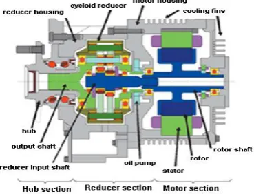
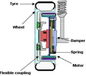
In this work, only the effect of mass of the electric motor will take into account. Figure(1) is a cross-section of the in-wheel electric motor system, which has a structure that aligns the hub, reducer section and the motor section in a series configuration. Figures(2)and(3).show the Michelin active tire with in-wheel motor and Bridgestone’s Dynamic-Damping In-wheel motor drive system.
Fig. 2 Michelin active tire with In-Wheel Motor.
Fig. 3 Bridgestone’s Dynamic-Damping In-Wheel Motor Drive System.
.
IV.ACTIVESUSPENSIONSYSTEMMATHIMATICALMODEL
Designing a suspension system is an interesting and challenging control problem. Also, Suspension system modeling serves two purposes: understanding system dynamics and developing control strategies. Models are simplified representations of physical systems, allowing focus on important system dynamics.
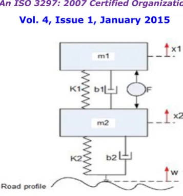
When the suspension system is designed, a quarter car model (one of the four wheels) is used to simplify the problem to a 1D multiple spring-damper system. A diagram of this system is shown below in figure(4). This model is for an active suspension system where an actuator is included that is able to generate the control force F to control the motion of the vehicle body.
The suspension itself is shown to consist of a spring k1, a damper b1and an active force actuator F . The sprung mass
m1represents the quarter-car equivalent of the vehicle body mass. The unsprung mass m2represents the equivalent mass
due to the axle and tire. The vertical stiffness and damper of the tire is represented by the spring k2.and b2 The variables
x1, x2and w represent the vertical displacements from static equilibrium of the sprung mass, unsprung mass and the road
respectively,[1].
Fig. 4 Double Mass-Spring-Damper used to model Active Suspension system.
V. SYSTEMPARAMETERS
(w ) Road displacement (x1) car body displacement
(x2) Un-sprung mass displacement
(b1) damping constant of suspension system =1000 N.m/s
(b2) damping constant of wheel and tire =0 N.m/s
(K1) spring stiffness constant =16000 N/m
(K2) Tire stiffness constant =160000 N/m
(m1) 1/4 car body mass(sprung mass) =250 Kg
(m2) unsprung mass =45 Kg
(mi) unsprung mass with in-wheel motor =(45+34)Kg* (F) control force
*The unsprung mass with in-wheel motor =(tire mass+ In-wheel electric motor mass)
*The motor mass assumed as 79Ibs(34Kg) which selected from Protean Electric productions.
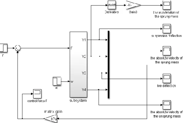
VI.SIMULINKMODELOFTHESYSTEM
Figure (5) shows The Simulink model of the active suspension system of quarter car model which built by using the two previous equations.
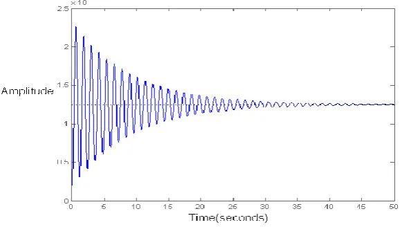
The result of the Simulink model above in figure(6) is the Open-Loop Response to 0.1 m Step Disturbance of active suspension system.
Fig. 6 Open-Loop Response to 0.1 m Step Disturbance of active suspension system
Observing the figure, it is necessary to improve the response of the suspension system through the control of the suspension control force F. the control method which will use to create the controller in this work is TheLinear Quadratic Regulator (LQR).
VII. LINEARQUADRATICCONTROL(LQR)
The theory of optimal control is concerned with operating a dynamic system at minimum cost. The case where the system dynamics are described by a set of linear differential equations and the cost isdescribed by a quadraticfunctioniscalled theLQ problem. One of the main results in the theory is that the solution is provided by the linear-quadratic regulator (LQR). The LQR is an important part of the solution to the LQGproblem. Like the LQR problem itself, the LQG problem is one of the most fundamental problems in control theory,[9].
To design a full state-feedback controller for the system, state-space equations should be determined and then it can use Matlab program to find the value of the controller.
To find the controller matrix K ,it should Add the following command to the end of m-file and run the MATLAB program.
K = lqr(A,B,Q,R)
In this study two controllers needed, one to the system without in-wheel electric motor and another one to the system with in-wheel electric motor.
The following program shows entering the system parameters and the state-space equations and the formula which used to find the matrix of the controller by Matlab.
%Quarter car model
k1=16000;b1=1000;b2=0;m1=250;m2=45;mi=79;k2=160000;
%state-space form
A1=[0 1 0 -1;-k1/m1 –b1/m1 0 b1/m1;0 0 0 1;k1/m2 b1/m2 –k2/m2 -(b1+b2)/m2]; A2=[0 1 0 -1;-k1/m1 –b1/m1 0 b1/m1;0 0 0 1;k1/mi b1/mi –k2/mi -(b1+b2)/mi]; B1=[0;1/m1;0;-1/m2];
B2=[0;1/m1;0;-1/mi]; C=eye(4)
Dp=zeros(4,2)
%Controller design %Q=zeros(4,4); %Q(2,2)=1e08;
R=0.0001; C2=zeros(1,4);
%C2(1,1)=1 %for the suspension deflection
%C2(1,2)=1 %for comfort, the absolute velocity of sprung mass %C2(1,4)=1 %for the absolute velocity of unsprung mass
C2(1,3)=1%for good road traction, high electric motor torque
p1=1000; Q1=p1*C2'*C2 p2=1000*100; Q2=p2*C2'*C2
%Values of gains
K1= lqr(A1,B1,Q1,R) %for the system without in-wheel motor
K2 = lqr(A2,B2,Q2,R) %for the system with in-wheel motor
By run the program above we can get the value of K matrix (matrix gain) to use it to improve the system response in figure(5) in .Two values of K will used which are K1= [-0.0000 1.0274 -41.1156 -2.1412] to active suspension system without in-wheel electric motor( standard tire) and K2= 1.0e+03*[-0.0000 0.0989 -4.1495 -0.2158] to active suspension system with in-wheel electric motor.
Fig. 7 Simulink model of active suspension system with controller.
VIII. SIMULATIONRESULTS
Figures (8) to (13)show Analysis and results of active suspension system for quarter car model for speed bump of 0.1 m (step input)and the effect of in-wheel electric motor mass on the system performance.
Fig. 8 Effect of IWM on the suspension deflection
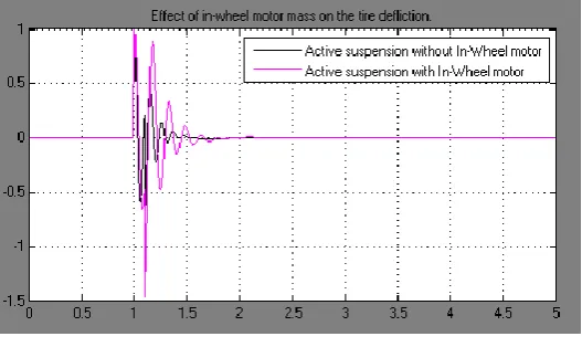
Figure (9)shows the influence of In-Wheel electric motor mass on the tire deflection which represent the road holding of the suspension system. It is obvious that using of In-Wheel motor gave negative effect of the car road holding.
Fig. 9 Effect of IWM on the tire deflection
Figure (10) presents the effect of In-Wheel electric motor mass on the velocity of the sprung mass in the suspension system. it is very clear the bad effect of using theIn-Wheel motor compared to use of standard tire.
Figure (11) presents the effect of In-Wheel electric motor mass on the unsprung mass velocity in the system. Also in this figure, using of In-Wheel electric motor obtained bad impact on the active suspension system performance..
Fig. 11 Effect of IWM on the velocity of unsprung mass
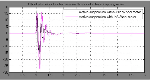
One of the important things which should take into account in the vehicles is the acceleration of the sprung mass(Quarter car mass in this study) which represent the driver comfort. In figure (12),using of In-Wheel electric motor gave negative performance of the system and caused bad comfort to the driver.
Fig. 12 Effect of IWM on the acceleration of sprung mass.
Figure (13) shows the effect of In-Wheel electric motor mass on the control force (Actuator force).Active suspension system with In-Wheel electric needs high actuating force to work compared to the same system without In-Wheel electric motor.
IX.CONCLUSION
This study shows a significant effect of the in-wheel electric motor mass on the active suspension system performance, some of this effect was clear on the sprung mass velocity and suspension deflection which represent the driver comfort and the road traction respectively. At same time the study explained that the active suspension with in-wheel electric motor requires high actuator force compared with the active suspension system without in-wheel motor. Finally, using of in-wheel electric motors in the vehicles has various negative aspects which caused little reliability to use it.
REFERENCES
[1] Rajesh Rajamani, "Vehicle Dynamics and Control", Springer publications, second edition, (2012).
[2] G. Eason, B. Noble, and I.N. Sneddon, “On certain integrals of Lipschitz-Hankel type involving products of Bessel functions,” Phil. Trans. Roy. Soc. London, vol. A247, pp. 529-551, April 1955.
[3] Ayman A. Aly, Car Suspension Control Systems: Basic Principles, International Journal Of Control, Automation, and Systems,VOL.1,
NO.1,2012.
[4] Abdolvhab Agharkakly, Ghobad, Shafiei Sabet, Armin Barouz, "simulation and analysis of passive and active suspension system using quarter
car model for deferent road profiles", International journal of engineering trends and technology – volume 3 issue 5-2012
[5] Sayel M. Fayyad, "construing control system for active suspension system", contemporary engineering sciences , vol.5,2012 ,no-4,189-200
[6] M. Senthil Kumar, S. Vijayarangan, "Analytical and experimental studies on active suspension system of light passenger vehicle to improve ride comfort", ISSN1392-1270.mehanica.2007-Nr.3(65).
[7] T. Rammohan Rao, G. Vekata Rao, K. Rao, A. Purushottam, "Analysis of passive and semiactive controlled suspension systems for ride comfort in an omnibus passing over a speed bump", LJRRAS 5(1). October 2010.
[8] V. Ganesh,K.Vasu,and P.Bhavana, "LQR Based Load Frequency Controller for Two Area Power System", International Journal of Advanced
Research in Electrical, Electronics and Instrumentation Engineering,Vol. 1, Issue 4, October 2012
[9] Martyn Anderson and Damian Harty, "Unsprung Mass with In-Wheel Motors", Myths and Realities, AVEC 10.
[10] Yuichi ITOH, Kayo SAKAI, and Yusuke MAKINO, "In-Wheel Motor System", NTN TECHNICAL REVIEW No.79(2011),
[11] Ying MA, Zhaoxiang DENG and Dan XIE,"Control of the Active Suspension for In-Wheel Motor", Journal of Advanced Mechanical Design