Snap-through-type nonlinear creep-buckling of a shallow sinusoidal shell
Natalia Plavnik l) and Heinz W Bargmann 2)1) S6cheron SA, Geneva Switzerland
2) Swiss Federal Institute of Technology, Lausanne, Switzerland, and University of Technology, Vienna, Austria ABSTRACT
This paper is concerned with creep and creep-buckling of the snap-through-type of a shallow, thin-walled, sinusoidal shell subjected to transverse (vertical) pressure. The material is governed by Odqvist's law of nonlinear viscoelasticity. The shell wall is modelled as a sandwich type to which any actual wall may be reduced and which has been described in detail by Hoff and others. The basic equations are formulated, and for a simply supported shell, approximate, analytic solutions are obtained describing the evolution in time of the deflection, i.e., the downward displacement of the initial rise. Instability is assumed to occur when the time rate of this deflection grows beyond all bounds. The time lapse after which instability occurs is called the "critical time" (lifetime) of the shell. It is of finite value for any loading, however small, as long as compressive stresses are created within the shell. If the shell exhibits nonlinear creep only, without elasticity as deformation mechanism, instability occurs when the shell traverses the horizontal plane. The effect of elasticity on the instability process results in a considerable reduction of the critical time. Here, instability occurs before the shell has reached the horizontal plane, as a snap-through phenomenon, as soon as the time rate of the deflection grows beyond all bounds.
1. I N T R O D U C T I O N
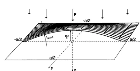
Consider a shallow, thin-walled, double sinusoidal shell, established over a square base of length a , in the horizontal x, y plane with origin O in the center of the base [1]. Let the middle surface of the shell in its initial (undeformed) configuration be described by the coordinates g , measured vertically upward from the base plane,
mc ny
g/= q~ cos ~ cos ~ (1)
a a
Fig. 1. Let the displacement components of a material point of the shell in the x, y, and z directions be denoted by u, v, and w, respectively. The load (per unit of the middle surface) distributed over the upper surface is denoted by p , and directed vertically downward.
...
V
_a/2_ _. x
/
a/2,'"
/ /
,,'y
;z
Fig. I.In the hope to arrive at a simple solution, possibly in closed form, we replace the actual structure by an idealized sandwich model due to Hoff [2]. There, two faces, carrying normal stresses only, are imagined to be of zero thickness held a distance D apart by a core, transmitting shear stresses only without deformation. Nevertheless, in each of these faces is concentrated one half the actual cross-sectional area of the real plate, and the distance D is chosen such that the moments of inertia of the real structure and the model are the same,
h real h real
h - , D - (2)
2
wher
hreal
is the wall-thickness of the real shell.SMiRT 16, Washington DC, August 2001 Paper # 2070
2. BASIC E Q U A T I O N S
In establishing the basic equations for the shell, we may start with those for the square plate subjected to the same loading, the middle plane deflection of which we denote by w e . Here we follow Tungl [3], who apparently was the first to study a snap-through-type creep-buckling problem for a shell, however for a linearly viscoelastic material. Let the normal stresses in the upper and lower faces be denoted by Crx,, Cry,, and Crxt, Cry t , respectively. Assuming that there are no body forces in the x, y plane and that the load is perpendicular to the p l a t e , we can reduce the equations of equilibrium of an element in the x, y plane to the following expression
(O'xl + O'XU ),XX -" (O'yl + O'yu ),yy ( 3 )
where ,x denotes partial differemiation with respect to x , etc. It is easy to see that the equilibrium in vertical z direction, with Eqs (3) taken into account, reads
£ [ ( O ' x l --O'xu),xx +(O'y 1 --O'yu),yy]+(O'xl +O'xu)W,Pxx +(O'y i +O'yu)W,Pyy + £ : 0
2 h (4)
For large deflections w P , the strain components in the middle plane are related to the displacements of that plane by
1 1 1 e e e
e" xo =U,x " + -2 (W~x) ~ , °°yO "--V,y + ~ " " ( w ' ~ ) ~ , °°xy 0 " = 2 ( u ~ + V'X + W,xW, y ) (5)
where the subscript 0 indicates the strain components in the middle plane z = 0 of the plate.
As long as the initial coordinates of a material point of the middle surface g of the s h e l l do not exceed the order of magnitude of the vertical displacement of the plate w e for which Eqs (3) to (5) are valid, we may imagine the deformed middle surface of the shell as a bent surface of a plate
w e = - ( V - w) = w - ~ (6)
but in such a way that the displacement ~ has been produced without strain since the shell is stressfree in its initial configuration. Equation (3) thus remains unchanged, Eq. (4) together with (6) yield
D r~t(~xl-~xu) + ( ~ y l - ~ y u ) , y y ~ ( ~ x , +~xu)(W-~C),xx +(~yl + °".,vu ) ( w - I/)r),yy + P = o
2 '~ h (7)
The geometric relations for the middle surface of the shell, where the strains are denoted by ex0, etc., are obtained from the plate relations, Eqs (5), which have the form 60 e = 60 e (u e, v 1", w e ) , by forming the difference
Thus
e (u, v, w - ~,) - 6 e ( 0 , 0 , - ~ )
S 0 = G O (8)
)
1 w2 _ W,x~',x = v y + = , , ( 9 )
O°xO = U,x -I--~ ,x , O°y 0 -~ W,y -- W,y~lZ,y, O°xy 0 -~ ,y + V x + W,xWy -- W x{bC,y -- W,y{Or,x
Upon elimination of u and v from Eqs (9); and subsequently setting the shear strain 6xy 0 equal to zero, since we also neglect the shear stresses in the faces of the shell, we obtain the following compatibility condition
OOxO,yy + OOyO,xx = F ( w , ~ ) (10)
2
F ( w , ~ ) = W, xy -2W,xy~,xy -W,xxW,yy + w,,~,yy + W,yy~,xx (11)
For a material point in the faces of the shell, at a distance + D / 2 from the middle surface, we obtain for the strains, with Kirchhoff's hypothesis,
D D D D
=xu
=°°x0
+TW,xx)
°°yu
==y0
+TW,yy)
°Cxl
=°~x0
"2 W,xx)
°~yl ==y0---~-W,yy (12)From Eqs (12) and (10) we obtain the following three geometric relations,
o~xt-~.x. =-DW,xx, ~ ' y l - 6 y . =-DW,yy, ('~xl +ex.),yy +(6yt +6y"),~ = 2 F ( w , g ) (13)
The material of the faces is assumed to exhibit nonlinear secondary creep and linear elasticity, according to Odqvist's nonlinear creep law [4]
n-1
2 G ~ U = h o. + 3 G K ( 3 1 2 ) -i- s~j, Ekkk = 6-~ (1--2V) (14)
The dot denotes differentiation with respect to time t ; e,j = g0 - ( 1 / 3 ) ~ a 6 , j and s o. =- cr U - ( 1 / 3 ) o ' ~ 6 o. are the deviators of the strain and stress tensor g0 and or0., respectively; 6 o is the Kronecker delta. Summation over repeated indices is implied. 12 - (1/2)s~js o. is the second invariant of so; E = 2G(1 + v) is the modulus of elasticity, G the shear modulus, v Poisson's ratio. The creep exponent n is here assumed to be an odd integer. The creep parameter K is highly dependent on temperature.
In the present case of a plane state of stress, we thus obtain
1 K ).-1
~x "- E-(ax
- V a y ) W y ( ° ' e q
(20- x -O-y),
~y
="-'~(l~'y --V(fJ'x)'k'y(O'eq )
1 K n-I(20"y
-O'x) ,
i 2
2
O'eq = O" x --O'xO'y "l-O'y
(15)Equations (15) must be written for each one of the two faces: in the upper face, for the strains 6x.,ey . , and the stresses o'x., Cry., and in the lower face, for the strains 6xi, Gyit, and the stresses o'xt, O-yit. Thus Eqs (15) represent four equations.
The differential equations
The two conditions of equilibrium, Eqs (3) and (7), together with the three geometric relations, Eqs (13), and the four constitutive relations, Eqs (15), are nine nonlinear partial differential equations for nine unknowns: the four stresses
O'x.,O'xt,o'y",Cry t the four strains 6 x . , 6 x t , 6 y . , Z y ~, and the deflection w. With the aid of the constitutive equations (15) we can now eliminate the four strains, thus reducing the system of nine equations to a system of five equations of five unknowns. Upon substitution of Eqs (15) into Eqs (13), once derived with respect to t, we obtain
_ _ K
1
[grx t _~rx"_ v((~.y I -(f~'yu )]-]-y [(O'eql )
E
n-I (20.xl _O.y i ) _(O.eq u
),,-1
(20.xu _O.y u )]=
_DfV,x ~°
- yu
-- V((fJ'xl --(fJ'xu )]'l-y [(O'eq I
K)n-I
(20.y i _ O.xl ) _(O.eq u
)n-1 (20.y u
_O.xu
) } -O]~2,yy
L [((~'xl "~- l(7"xu )
E
,yy
-- V((~'x, "{" l(Yxu )
,XX
"l- (l~'y, "t" ((I'yu )
,XX
-- V((~'y i
"1- (~'yu),yy ] (15)K
• -[---{ [(O'eq/)n-I (20"yl--O'xl)+(O'eql)n-l(20"yu--O'xu)L'-]-
[(O'equ)n-l(20"xl--O'yl)+(O'equ)n-l(20"xu--O'ul)~
}:
2P(W, ~//)
2
Boundary conditions
Let us assume that the shell is simply supported along the edges, thus
w = 0, Mx - 0 or Orxl = Orxu along x = +a / 2, w = 0, My -- 0 or Oryl = Oryu along y = +a / 2 (17)
since the bending moments are simply M x "-(orxl-Orx,) D h / 2 ,
My--(oryl-Oryu)
D h / 2 . Let us further assume that the edges remain straight and immovable during the deformation. Then the elongation o f the shell base, say in the direction x , is independent o f y and equal to zero. By Eqs (9) and (12) its value is equal toa/2 a/2
I
6 x = U,x dx = (ex,, + exi) + w,,,C/,x - 7 ,x -a / 2 -a / 2
(18)
Similarly,
a/2 a/2
--I
I[+
1
8y V,y dy = (gy,, "F gyl ) "F W,y~ff,y - - 7 W,y -a / 2 -a / 2
(19)
If we derive Eqs (18) and (19) with respect to time, and introduce the constitutive relations (15), we obtain the two conditions for immobility expressed in terms o f the stresses and the deflection,
aiZ 1 K
_a / 2 " ~ ~ x ' + t~'xu -- V( O'y I + t~'yu ) ]'l- "-~ [(oreql ) n-l ( 2orxl -- oryl ) + ( orequ )"-l ( 2orxu -- or yu ) ]F W,x (IPr,x -- W,x ) dx = O
,,/2 1 K
- J 2 " - ~ [(7"yl "q- ¢~'yu --V((7"xl "q- ¢~'xu ) ] ' ~ - ~ [(Oreql )n-1 (2ory! --orxl )'q'(orequ ) n-1 (2Cry. -Crxu )]~ ]42,y (~/,y --W,y ) dy = O
(20)
Finally, symmetry in the center point requiresS
Or xl --" Or yi and Or xu = Or yu for x = y = 0 (21)
3. S O L U T I O N P R O C E D U R E
The deflection o f the shell may be taken as a double sinusoidal form
nx ny (22)
w = W ( t ) c o s - - c o s ~
a a
which satisfies the boundary condition with regard to the deflections and the bending moments for any, yet unknown function
w ( t ) .
Similarly, the stresses may be represented by
ny . nx 70,
orxt = B0 (t) + B 1 (t) cos ~ cos ~ , Orx, = B0 (t) + B 1 (t) c o s ~ cos
a a a a
;fix ~Y , , ~:x 70,
Cry ! = A o (t) + A l (t) c o s - - c o s ~ , ory. = A o (t) + A 1 (t) c o s ~ c o s ~
a a a a
(23)
The boundary conditions with regard to the bending moments, Eqs (17) are satisfied if
The symmetry condition, Eqs (21), require
B o+B~ = A o+A~, B o + B~" = A o + A 1 (25)
Let us approximate the distributed vertical load by the double sinusoidal expression
nx ny = P 0 (t) cos ~ cos
P a a (26)
Upon substitution of Eqs (22) and (23) into the condition for equilibrium in the horizontal plane, Eq. (3), we obtain
B 1 + BI* = A~ + A~ (27)
The five algebraic relations, Eqs (24), (25), and (25) yield
A I = B l, A 1 = B l, A 0 = A 0 = B o = B 0 (28)
Upon substitution of Eqs (22) and (23) into the condition for equilibrium in the vertical direction, Eq. (7), using Eqs (28), we Obtain
ny ~__
Po 4B o ( ~ W ) + D ( B ~ B I) c o s ~ c o s ~ c o s 2 = 0
- ~ + -- -- - - -I" 2 Lid -- W I ( B 1 + a ; ) c o s 2 ~
a a a a (29)
Equation (29) must be satisfied for arbitrary x, y , hence each coefficient must vanish. We thus obtain
B~* = - B 1 (30)
and
r'~k,
)/~/~-
POh = 4 B ° ( W - W ) + 2 D B I (31)Equations (28) and (30) are six equations for eight unknowns. Thus the stresses can be expressed by two yet unknown functions of time, Bo(t ) and B 1 (t),
O'xi = O ' y I = B o (t) + B 1 (t) c o s ~ cos 70,, O'x, = O'yu = B 0 (t) - B 1 (t) c o s ~ c o s ~ (32)
a a a a
We still have to satisfy Eqs (16), and the boundary conditions of immobility, Eqs (20). Upon substitution of Eqs (22) and (32) into Eq. (16)1, one obtains
3KB~B 1 - D , W + Bl c o s ~ c o s ~ + KB~ cos 3 ~ cos ~ = 0 (33)
a a a a
Making use of the identity
1
cos 3 a cos 3 fl = 7-7.(9 cos a cos fl + 3 cos a cos 3fl + 3 cos 3 a cos fl + cos 3 a cos 3fl)
l O
(34)
/
/
3KB1 Bo 2 + B2 + /~1 = D I'//" (35)
E
The same result is obtained from Eq. (16)2. Finally, Eq. (16)3 is identically satisfied; cf. [ 1 ]. Finally, the two conditions of immobility, Eqs (20), yield the same result,
KB o B~ + ~ B? + E B° = -2 V V ( W - re) (36)
Thus the basic equations are f'mally reduced to the set of three nonlinear ordinary differential equations, Eqs (31), (35), and (36), for the three functions of time, the membrane stress B 0 (t), the bending moment B~ (t), and the deflection W ( t ) .
Initial conditions for creep-buckling
The basic equations for the elastic snap-through problem follow directly from Eqs (31), (35), and (36), for K = 0, upon integration,
(_~] 2 P° = 4B°e - ql) + 2DBle
2(1- v) B1 e _. O W e (37)
E
where the subscript e indicates the elastic situation. Upon substitution of Eqs (37)2 and (37)3 into (37)1, we obtain the following cubic equation for the elastic deflection at the center of the shell W e , as a function of the initial height of the shell
W and the lateral pressure P0"
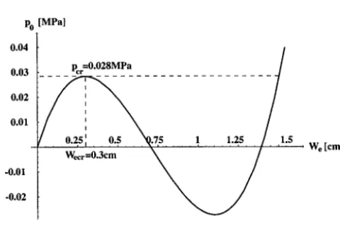
Po = 2(1- v - - - S W e [ ( W e - kIZl)(me - 2W) + 2D 2 ] (38)
cf. Fig. 2. After the deflection W e has been found, B 0 and B~ follow directly from Eqs (37)3 and (37)2.
Po [MPa] 0.04
0.03
0.02
0.01
-0.01
-0.02
PcrO.O28MPa
___
.75 1 1.25 .5
, . . " ,
Wecr=O.3cm : We [cm]
Fig. 2.
Pcr = p o ( W c r ) = ( l _ v )
at the deflection
1 4~p2
Wec r
= V - - - " ~ - 2 D 2 (40)corresponding to Opo/OW e = 0. From Eqs (39) and (2), a sufficient condition for the existence of a real-valued critical
pressure Per is given by • > D,J2 - h~e,, l ~ / 3 , which for thin-walled shells is always fulfilled.
The creep-bulding process
Immediately after load application and also for the major portion of the lifetime, the displacements, and consequently also the stresses accompanying the displacements, are small [1 ],[2]. Thus
IB, I <<lB01
(41)The basic equations, Eqs (31), (35), and (36), then reduce to the following two equations [ 1 ]
KB~ +
( a ) 2 P0h = 4 B ° ( W - W )
2(1- v/~,'~o 1
~/(w
~ )E
=2
(42)
Upon substitution ofEq. (42)~ into Eq. (42)2, we obtain
/a/4
1 = 32h 3 W ( 1 - v ) p oKpo
E7
(W - kI-/) + (W - klJ) 4 I
(43)and upon integration,
/~/Sf
/a.~/4
1
]t
t = 32h3Kp3o (1- v)P°2Eh
[(W- kI/)2-(We -kIJ)2 ]b 5 [(w - kIJ)5
-(We
- kIJ) 5
(44)It follows from Eq. (43), that the time rate of change of the deflection grows beyond all bounds, W ~ ~ , at a finite (critical) value of the deflection, according to
(I--V)PoI-~I
4(w-kr~)+(w-~xj)4=Oeh
~
(45)hence, at
I'l 'p°la)
and Wcr 2 = W (46)/a/4
'
tc~ = 3_2h~Kp
3 ( 1 - v)P°2gh[(Wcrl -
k l J ) 2 - ( W e - k [ I ) 2 ] a t - 5[(Wcrl
- k I ' / ) 5 - ( W e - kI'/)5 (47)Thus, for any lateral loading, however small, there is a finite critical time at which creep-buckling of a snap-through type
OCCurS.
W [cm]
1.5
1.25
0.75
0.5
0.25
~estiC solution -~ ~ • ...-
.W~r~=0 7cm /' [ ~ " = /) . . .
i
WcrJ =0"41cm ~ l
. . . j l
_"~S~..~..~'.i . , . . .
50 100 150 200 250 300 t [hours]
Fig. 3.
Example
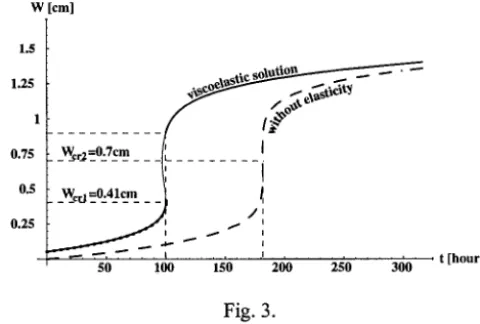
Consider a shell with a square base of length a = 20 cm, initial height W = 0.7 cm, and wall-thickness hreal = 0.07 cm, made of lead, commercial quality, subjected to a lateral load P0 ~ 0.01MPa, at the elevated temperature of 30°C. We have Young's modulus E ~ 14000 MPa, Poisson's ratio v = 0.3, creep exponent n = 3, and creep parameter or c7 ~ 1MPa, where
.3 K - 1 0 -7 O'c7 .
We note that the critical pressure for elastic snap-through is Pcr = 0.03 MPa, at a critical deflection Wcr = 0.3 cm. Under a pressure of P0 ~0.01MPa, the initial elastic deflection is W e =0.05cm. The shell then creeps until a deflection Wc~ = 0.41 cm is reached, and finally snaps through, at the critical time t cr - - 1 0 0 h o u r s , Fig. 3. Comparison with a second curve, clearly exhibits the influence of elasticity. When elasticity is not taken into account as deformation mechanism, a greatly increased critical time would be obtained; there would be no snap-through, though the deflection would pass through the horizontal base plane with instantaneous velocity approaching infinity, Fig. 3.
REFERENCES
1. Plavnik, N., Fiabilit~ et instabilit~ par fluage d'une coque plate soumise ?t des sollicitations thermom~caniques, Doctoral Thesis, Swiss Federal Institute of Technology, EPF Lausanne, 1998.
2. Hoff, N.J, "Creep buckling of rectangular plates under uniaxial compression", in: F.A. Leckie and J. Heyman (eds),
Engineering Plasticity, Cambridge UniversityPress, London, 1968.
3. Tungl, E., "Durchschlagen einer flachen Kugelschale aus viskoelastischem Material", Osterreichisches Ingenieur-Archiv
16, 1962.
4. Odqvist, F.K.G., Mathematical Theory of Creep and Creep Rupture, Oxford University Press, London, 1966.