STRUCTURAL INTEGRITY ISSUES IN HIGH TEMPERATURE
NUCLEAR PLANT: EXPERIENCE FROM OPERATION OF THE UK
ADVANCED GAS COOLED REACTOR FLEET
David W Dean and Julian G Johns
Assessment Technology Group, EDF Energy, UK
ABSTRACT
The Advanced Gas Cooled Reactor (AGR) fleet operated by EDF Energy in the UK are a unique example of high temperature civil nuclear plant that has operated commercially over significant timescales. AGR plant contain a graphite core with carbon dioxide used as the primary coolant and importantly key metallic boiler, reactor internal and fuel route components operate within the creep range, at temperatures up to 650oC. Some of the AGR plant have now operated for periods in excess of 250,000 hours.
This paper first describes the important features of a typical AGR power station and outlines the key degradation mechanisms that need to be considered when assessing the lifetime of key metallic components. This is followed by a brief summary of the Component Life Assessment (CLA) process that is used by EDF Energy to monitor and review the fractional life usage of AGR boiler and reactor internal components. Then some examples of issues that have affected the structural integrity of key high temperature AGR components are discussed, focussing on how these issues have been managed. Finally, consideration is given to ways that experience from operation of the UK AGR fleet can be used to inform the design and operation of future high temperature reactors.
ADVANCED GAS COOLED REACTORS
The Advanced Gas Cooled Reactor (AGR) fleet operated by EDF Energy in the UK are a unique example of high temperature civil nuclear plant that have operated commercially over significant timescales, noting that some of these plant have now operated for periods in excess of 250,000 hours. AGR plant contain a graphite core with carbon dioxide used as the primary coolant and importantly key metallic boiler, reactor internal and fuel route components operate within the creep range, at temperatures between 480˚C and 650˚C.
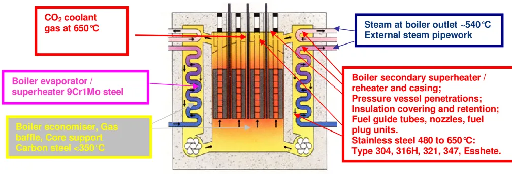
Fig. 1 Schematic AGR layout focussing on components within the concrete reactor pressure vessel.
The original design life of the AGRs was typically 30 years, although some reactors have already operated beyond their original design lives and further lifetime extensions are being planned for all AGRs. Managing the structural integrity of key metallic AGR components within the concrete pressure vessel over extended lifetimes places increased emphasis on understanding and being able to predict the degradation mechanisms that affect these components.
DEGRADATION MECHANISMS AFFECTING METALLIC AGR COMPONENTS
Many of the austenitic stainless steel boiler, reactor internal and fuel route components are subjected to creep-fatigue loading, often involving relatively high thermal stresses during start-up/shutdown cycles and other transients. These components typically experience a few hundred start-up/shutdown cycles in reactor lifetime. Recent work has highlighted the potentially detrimental effect of the reactor gas CO2
environment on some of these components, which can lead to surface carburisation and consequent reductions in creep ductility and fatigue endurance (Chevalier, 2015).
The degradation mechanism of concern for most of these components is creep (or creep-fatigue) damage, including reheat cracking, and this is the focus of this paper. Other relevant degradation mechanisms that need to be considered include oxidation (metal loss), carburisation (involving hardening and embrittlement of the surface layer in contact with the reactor gas CO2 environment) corrosion (including
stress corrosion cracking), fretting, high cycle fatigue and thermal ageing. It is also important to consider the potential for synergistic effects involving interactions between degradation mechanisms; of particular concern here is the potential effect of surface carburisation on the development of creep and creep-fatigue damage in affected components (Chevalier, 2015).
COMPONENT LIFE ASSESSMENT (CLA) PROCESS
Component Life Assessment (CLA) is the process that is used by EDF Energy to monitor and review the fractional life usage of AGR boiler and reactor internal components (i.e. within the concrete rector pressure vessel as shown in Figure 1) due to service exposure to high temperatures and/or cyclic loadings which give rise to creep-fatigue damage accumulation (Bradford, 2013). For each AGR, a set of
Steam at boiler outlet ~540°C External steam pipework
½CMV
Boiler evaporator / superheater 9Cr1Mo steel 350 to 480°C
Boiler economiser, Gas baffle, Core support Carbon steel <350°C
CO2 coolant
gas at 650°C
Boiler secondary superheater / reheater and casing;
Pressure vessel penetrations; Insulation covering and retention; Fuel guide tubes, nozzles, fuel plug units.
representative boiler and reactor internal components have been defined for use in the CLA process, which are referred to as the Life Assessment Reference Components (LARCs). These will include:-
• Components which have been identified as likely to have high rates of damage accumulation, and whose failure has nuclear safety or commercial significance, unless the component has been shown to be bounded by another component in the LARC set.
• Examples of components likely to exhibit particular sensitivity to any of the key transient parameters, e.g. reactor gas pressure, pressure differentials or gas temperatures.
• Components determined on a design specific basis as being of particular importance, interest or vulnerability.
• Any components which have been identified as of particular lifetime significance.
• Inclusion of other components in the LARC set is discretionary. However it is desirable to include more ‘typical’ components as examples of each major plant area, or as examples of the different materials of construction and classes of welds.
It is not possible to represent all boiler and reactor internal features in the LARC set, but it is intended that the LARC set for each AGR should include sufficient components/features to be bounding. As most of these reference components are located within the reactor pressure vessel and are often in inaccessible locations, they are often very difficult to adequately inspect, repair or replace. Managing the lifetime of these components using the CLA process relies very heavily on predictions of damage and there is a need to ensure that reliable material properties data and assessment methodology are available for this purpose. Most reference components are currently assessed using the R5 high temperature assessment procedure (EDF Energy, 2014; Dean et al., 2015).
The CLA process is generally based on deterministic assessments using bounding material properties and assumptions and it is recognised that this approach will generally give very conservative predictions of component damage. This is particularly the case in the creep regime due to the large intrinsic scatter in creep data, and the sensitivity of creep to both temperature and stress, and the adoption of bounding data. Probabilistic methods may be helpful in situations where deterministic assessments using bounding assumptions suggest that damage levels are higher than defined acceptance levels. Probabilistic assessments can provide a quantification of the degree of risk in terms of the anticipated frequency (or probability) of cracks initiating (Holt and Bradford, 2012; Bradford and Holt, 2013; Bradford, 2015). This can be particularly helpful in addressing the lifetime threat for components (such as boiler tubes) where small numbers of anticipated cracks (or leaks, or failures) do not challenge either the safety or the commercial viability of the plant. In addition, bounding deterministic assessments are of questionable relevance for predicting the future behaviour of populations of components where some failures (or cracks or leaks) have already occurred.
EXAMPLES OF HIGH TEMPERATURE STRUCTURAL INTEGRITY ISSUES
This section describes two examples of high temperature structural integrity issues that resulted in creep or creep-fatigue cracking in key AGR plant components and how these issues have been managed.
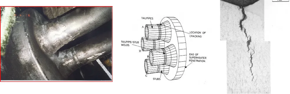
Creep-Fatigue Cracking in Boiler Superheater Bifurcation and Tailpipe-Pintle Welds
These are Type 316 welds in Type 316H tubing, with thicknesses of approximately 4mm (bifurcations) and 7mm (tailpipe-pintle welds), see Figures 2 and 3. The bifurcation welds were solution heat treated but the tailpipe-pintle welds were not subjected to post weld heat treatment. These welds operated at ~500-525˚C at full power with a CO2 reactor gas environment on the outer surface and superheated steam on
number of leaks had occurred, the situation was being managed by a combination of isolation, repair and replacement. In all cases, cracking occurred in the heat affected zones on the outer surface of the welded components (i.e. on the surfaces exposed to the CO2 reactor gas environment). However, in 2006 there
was a significant increase in the number of reported defects from inspection of these components. This was in part due to improvements in inspection detection capability, but also pointed to ongoing degradation in the integrity of these components, which was primarily attributed to creep mechanisms occurring during operation at full power. The outcome for future plant operation was to down rate the power output (to ~80% of full power) and hence lower temperatures to ameliorate creep mechanisms, in conjunction with more rigorous inspection schedules and some ongoing component repairs and replacements.
Detailed metallurgical investigations of some of the observed defects were carried out in order to develop an improved understanding of the issue. These confirmed a creep dominated creep-fatigue growth mechanism was responsible for crack growth, see Figure 2 (bifurcation weld) and Figure 3 (tailpipe-pintle weld). However, the mechanism that caused the cracks to initiate was less clear, partly because the initiation sites had long since been consumed by oxidation. The R5 procedure (EDF Energy, 2014; Dean et al., 2015) was used to carry out both creep-fatigue initiation (R5 Volume 2/3) and crack growth (R5 Volume 4/5) assessments for the bifurcation and tailpipe-pintle welds. As the bifurcation manufacturing process was particularly complex, detailed 3D finite element analyses of the both fabrication and in-service loading of the structure were carried out to inform these assessments (Bray et al., 2010). The outcome of these deterministic R5 assessments for the bifurcation and tailpipe-pintle welds was that while observed creep-fatigue crack growth rates were broadly consistent with assessment predictions, it was not possible to predict creep-fatigue crack initiation in the bifurcation welds.
Probabilistic R5 Volume 4/5 creep-fatigue crack growth assessments for the bifurcations, which crucially accounted for uncertainties in both the prediction of crack growth and in the inspection process, resulted in predictions that were consistent with the observed crack growth behaviour (Holt and Bradford, 2012). Subsequent investigations have shown that the inability of R5 Volume 2/3 to predict the initiation of cracking in the bifurcation welds is because it does not currently account for the deleterious effect of carburisation on creep-fatigue initiation behaviour. Further developments of the R5 Volume 2/3 procedure have been proposed to include the effect of surface carburisation in creep-fatigue initiation assessments (Chevalier, 2015). Further probabilistic R5 Volume 2/3 assessments have also been carried out to demonstrate that the observed incidence of cracking in the bifurcation welds is not consistent with creep-fatigue initiation in nominal (i.e. unaffected by carburisation) material, which helps to consolidate the hypothesis that surface carburisation plays a significant role in the formation of cracks in these components (Bradford, 2015).
In summary, the cracking observed in boiler superheater bifurcation and tailpipe-pintle welds has shown that surface carburisation, which can occur during high temperature exposure in a pressurised AGR CO2
Figure 2. Creep-Fatigue Cracking in Bifurcation Welds.
Figure 3. Creep-Fatigue Cracking in Tailpipe-Pintle Welds.
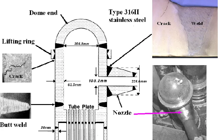
Reheat Cracking in Boiler Superheater Header Welds
Reheat cracking was originally found in AGR steam pipework and penetrations in the late 1980s. Cracking occurred in the heat affected zone (HAZ) or strain affected zone (SAZ) of thick section non-post weld heat treated Type 316H welds (Neumann et al., 1999). The majority of incidents were associated with welds in thick section (63.5 mm thick) superheater headers as shown in Figure 4.
These welds operated at ~510-550˚C with an air environment on the outer surface and superheated steam on the inner surface. These welds are therefore not affected by carburisation resulting from exposure to the pressurised AGR CO2 reactor gas environment. Mechanical (pressure and system) stresses are modest
for these welds, although all of these welds initially have high welding residual stresses as they were not post weld heat treated. Reheat cracking has occurred in many of these welds (see Figure 4), typically after operating times between 10,000 and 80,000 hours. Metallurgical examination of the cracking (Coleman et al., 1998) showed that the reheat cracks initiated near the outer surface of the header in the HAZ or SAZ and extended part-way through the header wall, typically to a depth less than half the wall thickness.
90o
180o
270o
View from above
0o
In addition, scanning electron microscopy revealed cavitated grain boundaries in and ahead of the cracks, confirming that reheat cracking is caused by a creep dominated mechanism.
Reheat cracking initiation is generally predicted by firstly modelling the welding process and hence estimating the magnitude and distribution of the residual stresses (Smith et al., 2012). In addition to the magnitude of the welding residual stresses, the degree of triaxiality is an important factor in determining the susceptibility of components to reheat cracking. Other service loadings (e.g. pressure and system stresses) are then applied to the finite element model of the weldment, which is then subjected to creep over a representative operating temperature history. Creep damage is then evaluated using the ductility exhaustion approach in R5 Volume 2/3 (EDF Energy, 2014; Dean et al., 2015), taking account of the effect of the multiaxial stress state on creep ductility. Reheat cracking predictions using this approach are generally consistent with observed incidences of cracking in Type 316H AGR plant welds.
As widespread reheat cracking was observed in most of the population of superheater headers shown in Figure 4, a programme of header replacement has been in place since reheat cracking was first discovered and nearly all of the original Type 316H headers have now been replaced with an improved design manufactured using a higher ductility, lower carbon type of 316 steel. This involves replacing all of the original header shown in Figure 4 including the weld immediately above the tubeplate. This approach to managing the ongoing lifetime of these components was possible because these superheater headers are external to the reactor pressure vessel and are therefore more accessible than components within the reactor pressure vessel.
In summary, reheat cracking has been observed in the HAZ or SAZ of a significant number of thick section non-post weld heat treated Type 316H welds. Reheat cracking predictions, that use finite element modelling of the residual stresses in conjunction with R5 Volume 2/3 estimates of creep damage during high temperature operation, are generally consistent with observed incidences of reheat cracking in Type 316H AGR plant welds.
MATERIAL EFFECTS ON CRACKING IN HIGH TEMPERATURE AGR TYPE 316H COMPONENTS
The specification limits used to procure Type 316 (generally 316H) steels at the time of AGR construction means that a relatively wide range of chemical compositions were used in component manufacture. In addition, it is known that Type 316 steels were procured from a number of different steelmakers and that a wide range of processes were used to manufacture Type 316 components in a wide range of section thicknesses. It is therefore recognised that there will be significant scatter in the creep properties of these materials, which is likely to be dominated by cast to cast variability. Therefore identifying whether particular casts have a high propensity to creep damage in AGR plant components may help to explain historic plant behaviour and help to identify future concerns.
EDF Energy has carried out some preliminary studies which considered the chemical composition of boiler material used in the manufacture of the boiler superheater bifurcation components described earlier in this paper. This identified three distinct sources of material, manufactured by three different steelmakers, which had significantly different chemical compositions. Whilst all three sources of material have been found to be susceptible to degradation it was concluded that it was likely that susceptibility to developing creep damage and hence cracking in bifurcation welds is influenced by the steelmaking process and chemical composition (noting that the manufacturing processes were nominally identical for all bifurcation components). Interestingly, the superheater headers described earlier that suffered extensive reheat cracking were also manufactured by the same steelmaker and had similar chemical compositions to the most susceptible bifurcation material (despite the significant differences in component manufacturing processes and section thicknesses).
In summary, these preliminary studies suggest that susceptibility to developing creep damage and hence cracking in plant components is influenced by the steelmaking process and chemical composition. Further work is required to examine whether these preliminary findings could be used to inform future lifetime management strategies.
IMPLICATIONS FOR FUTURE HIGH TEMPERATURE REACTOR DESIGNS
The experience from operation of the UK AGR fleet can be used to inform the design and operation of future high temperature reactor reactors. This section summarises some of the lessons learnt from long-term operation of austenitic stainless steels (mostly the 300 series grades) at high temperatures (in the creep range for these steels.
1. Creep or creep-fatigue cracking invariably occurs in the heat affected zone (HAZ) or strain affected zone (SAZ) of weldments; this is generally true for all relevant grades of austenitic steels used in the AGRs, for a wide range of section thicknesses (from ~3mm to ~64mm) and whether or not the welds have been solution treated or post weld heat treated.
2. Cracking is often associated with high levels of secondary stress, often arising from operational thermal transients and/or welding residual stresses in non post weld heat treated welds.
3. Cracking tends to occur in materials with low creep ductility, for example the HAZ or SAZ of thick section Type 316H welds.
4. Carburisation can occur at the surface of components during high temperature exposure in a pressurised AGR CO2 reactor gas environment and this can affect the initiation of cracks in these
components when subjected to creep-fatigue loading. This is likely to have the most significant effect on the integrity of thin section components.
This operational feedback from the UK AGR fleet has provided key drivers for ongoing development of EDF Energy’s R5 high temperature assessment procedure (EDF Energy, 2014; Dean et al., 2015). However, many of the issues identified above are not currently addressed in existing high temperature design codes.
In addition to the issues identified above, which relate to lessons learnt from long-term operation of austenitic stainless steel components, it is instructive to comment on improvements that could be made in designing surveillance schemes for future high temperature reactors. During AGR design, it was recognised that oxidation would potentially affect the lifetime of metallic components operating at high temperatures and an Oxidation Monitoring Scheme (OMS) was set up that involved exposing components and parts of components in pressurised AGR CO2 reactor gas environments at a range of relevant elevated
temperatures. The OMS has continued to provide valuable information on oxidation behaviour over plant timescales and has also been used more recently to investigate when carburisation occurs in austenitic materials. However, the major shortfall of the AGR oxidation monitoring scheme is that none of the surveillance samples are subjected to any loading. Surveillance schemes for future high temperature reactors should therefore consider exposing samples in a relevant reactor environment and subjecting them to loadings experienced by typical plant components.
CONCLUDING REMARKS
This paper has described the important features of a typical Advanced Gas Cooled Reactor (AGR) power station and has outlined the key degradation mechanisms that need to be considered when assessing the lifetime of key metallic components. The Component Llife Assessment (CLA) process that is used by EDF Energy to monitor and review the fractional life usage of AGR boiler and reactor internal components has been briefly summarised. Then two examples of high temperature structural integrity issues that resulted in creep or creep-fatigue cracking in key AGR plant components have been described, together with the strategies that have been adopted to manage these issues. The two examples described are: (i) creep-fatigue cracking in boiler superheater bifurcation and tailpipe-pintle welds; (ii) reheat cracking in boiler superheater header welds. Although there are significant differences in the section thicknesses of these components and the service loadings, there are a number of common features of the cracking, namely the material (Type 316H), location (heat affected or strain affected zone) and the operating temperatures (~500-550˚C). Finally, consideration has been given to ways that experience from operation of the UK AGR fleet can be used to inform design and operation of future high temperature reactors.
ACKNOWLEDGEMENT
This paper is published by permission of EDF Energy Nuclear Generation Ltd.
REFERENCES
Bradford, R. A. W. (2013). “AGR power stations’ boiler and reactor internals: ground rules for creep and fatigue component life assessment (CLA)”, EDF Energy Company Technical Standard (Mechanical) BEG/SPEC/ENG/CTS/209.
Bradford, R. A. W. (2015). “Application of probabilistic assessments to the lifetime management of nuclear boilers in the creep regime”, Proc SMiRT 23, Manchester, UK.
Bray, D. P., Dennis, R. J. and Bradford, R. A. W. (2010). “Modelling the complex manufacturing history of a pipework joint and assessment of its through-life creep-fatigue damageusing finite element based methods”, Proc 2010 ASME PVP Conf, Bellevue, Washington, USA.
Chevalier, M. J. (2015). “Development of the R5 Volume 2/3 procedure to enable the creep-fatigue crack initiation assessment of carburised stainless steel components”, Proc SMiRT 23, Manchester, UK. Coleman, M. C., Miller, D. A. and Stevens, R. A. (1998). “Reheat cracking and strategies to assure integrity of Type 316 welded components”, Proc Int Conf on Integrity of High Temperature Welds, Hottingham, UK, 169-179.
Dean, D. W., Allport L.C. and Chevalier M.J. (2015). “The R5 procedures for assessing the high temperature response of structures: current status and recent developments”, Proc SMiRT 23, Manchester, UK.
EDF Energy (2014). “R5: Assessment procedure for the high temperature response of structures”, Issue 3 Revision 002, Gloucester, UK.
Holt, P J. and Bradford, R. A. W. (2012). “Application of probabilistic modelling to the lifetime management of nuclear boilers in the creep regime: Part 1”, Int J Pres Ves Piping, 95, 48-55. Neumann, P., Miller, D. A. and Ainsworth, R. A. (1999). “Material factors which influence remaining life
of components subject to reheat cracking”, Fracture, Plastic Flow and Structural Integrity, Proc 7th TAGSI Symposium, TWI, Abington, UK, 175-184.