A Comprehensive Survey on Efficient Routing
Protocols And Simulation Tools For VANET
M.Siva Sangari Dr.K.Baskaran
Research Scholar Associate Professor
Anna University,Chennai Dept of CSE ,GCT,Cbe
Abstract-Vehicular Ad-Hoc Network or VANET is an emerging technology in the modern world .Here moving vehicles act as nodes in a network to create a dynamic network. Vehicular Ad-hoc Networks can be viewed as main component of the Intelligent Transportation Systems (ITS). Vehicular networks provide two types of communications: Vehicle –to-Vehicle, Vehicle-to-Roadside. Vehicular Ad-hoc Networks communicate based on Dedicated Short Range Communications (DSRC) which is a type of WiFi, Cellular, Satellite, and WiMAX. The Communication is based on the Wireless Access for Vehicular Environment (WAVE) dedicated to vehicle-to-vehicle and vehicle-to-roadside communications. There are specialized routing protocols for Vehicular communications such as Fisheye State Routing (FSR), Ad Hoc On Demand Distance Vector (AODV), AODV+PGB – Preferred Group Broadcasting (PGB), DSR – Dynamic Source Routing (DSR), TORA – Temporally Ordered Routing Algorithm (TORA), Greedy Perimeter Stateless Routing (GPSR), GPSR+AGF – Advanced Greedy Forwarding (AGF), PRB-DV – Position-Based Routing with Distance Vector Recovery (PBR-DV), GRANT – Greedy Routing with Abstract Neighbor Table (GRANT), Greedy Perimeter Coordinator Routing (GPCR).The future applications of Vehicular networks include maintaining safe distances between vehicles , alerting the driver of emergency vehicles , providing dynamic switching between various lanes.
Keywords: Vehicular Networks, AODV, DSR, Dedicated Short Range Communications (DSRC), Wireless Access for Vehicular Environment (WAVE).
1. INTRODUCTION
Vehicular Ad-Hoc Network, or VANET is a technology that uses moving cars as nodes in a network to create a mobile network. VANET turns every participating car into a wireless router or node, allowing cars approximately 100 to 300 metres of each other to connect and, in turn, create a network with a wide range. VANET provides a wireless communication between moving vehicles, using a dedicated short range communication (DSRC). DSRC is essentially IEEE 802.11a amended for low overhead operation to 802.11p which is being standardized by IEEE as Wireless Access in Vehicular Environments (WAVE). These types of communications allow vehicles to share different kinds of information, for example, safety information for the purpose of accident prevention, post-accident investigation or traffic jams. Other type of information can be disseminated such as traveller related information which is considered as non-safety information. The intention behind distributing and sharing this information is to provide a safety message to warn drivers about expected hazards in order to decrease the number of accidents and save people's lives, or to provide
passengers with pleasant journeys. Though there are many applications related to Routing in Vanet there are many issues also. Hartenstein and Laberteaux (2008) have investigated the communication and networking aspects of this technology and addressed the security and privacy issues. While, Li and Wang (2007) focus on the routing protocols of VANET and their requirements to achieve better communication time with less consumption of network band- width. Lin et al. (2010) investigate the categories of routing protocols in VANET and the idea behind each of them. In this paper, I have presented the comprehensive survey about the various protocols and the simulation tools available for VANET.
2. VANET ARCHITECTURE
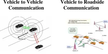
There are two types of communication available in regarding VANET- V2V and V2R.Vehicle can communicate with other vehicles directly forming vehicle to vehicle communication (V2V) or communicate with fixed equipment next to the road, referred to as road side unit (RSU) forming vehicle to infrastructure communication (V2I) (Olariu and Weigle, 2009; Moustafa and Zhang, 2009; Jiang et al., 2006).
Vehicle to Vehicle Vehicle to Roadside Communication Communication
Fig 1. VANET Communications
other vehicles or RSUs through the wireless medium; it also carries a single or multiple AU that use the applications provided by the provider using OBU connection capabilities. The RSU can also connect to the Internet or to another server which allows AU's from multiple vehicles to connect to the Internet.
2.1 On Board Unit (OBU)
An OBU is a wave device usually mounted on-board a vehicle used for exchanging information with RSUs or with other OBUs. It consists of a resource command processor (RCP), and resources include a read/write memory used to store and retrieve informa- tion, a user interface, a specialised interface to connect to other OBUs and a network device for short range wireless communica- tion based on IEEE 802.11p radio technology. It may additionally include another network device for non-safety applications based on other radio technologies such as IEEE 802.11a/b/g/n. The OBU connects to the RSU or to other OBUs through a wireless link based on the IEEE 802.11p radio frequency channel, and is responsible for the communications with other OBUs or with RSUs; it also provides a communication services to the AU and forwards data on behalf of other OBUs on the network. The main functions of the OBU are wireless radio access, ad hoc and geographical routing, network congestion control, reliable message transfer, data secur- ity and IP mobility (C.C. Communication Consortium; Ieee trial-use standard for wireless access in vehicular environments; Olariu and Weigle, 2009).
2.2 Application Unit (AU)
The AU is the device equipped within the vehicle that uses the applications provided by the provider using the communication capabilities of the OBU. The AU can be a dedicated device for safety applications or a normal device such as a personal digital assistant (PDA) to run the Internet, the AU can be connected to the OBU through a wired or wireless connection and may reside with the OBU in a single physical unit; the distinction between the AU and the OBU is logical. The AU communicates with the network solely via the OBU which takes responsibility for all mobility and functions
2.3 Roadside Unit (RSU)
The RSU is a wave device usually fixed along the road side or in dedicated locations such as at junctions or near parking spaces. The RSU is equipped with one network device for a dedicated short range communication based on IEEE 802.11p radio technology, and can also be equipped with other network devices so as to be used for the purpose of communication within the infrastructural network
According to C.C. Communication Consortium, the main functions and procedures associated with the RSU are: 1. Extending the communication range of the ad hoc network by re-distributing the information to other OBUs and by sending the information to other RSUs in order to forward it to other OBUs.
RSU work as information source (running safety applications)
RSU provides internet connectivity to the OBUs.
3. TAXONOMY OF VANET ROUTING
VANET has several properties that can be exploited for routing. They are connectivity, mobility, infrastructure, geographic location, and probability of its dynamics. According to which property is used, VANET routing techniques can therefore be classified as connectivity-based, mobility connectivity-based, infrastructure-connectivity-based, geographic-location-based and probability-model-based, Connectivity is formed by enlisting transceivers which can enable the communication network among vehicles. The communication network is a platform to propagate messages. The simplest routing method is based on flooding, where route request messages are broadcasted to every node in the network.
There are some well-known flooding-based routing protocols such as AODV, DSR and DSDV, proposed originally for MANET and extendable to VANET. Mobility is a unique property that does not exist in traditional fixed networks like Ethernet and ATM. It is normally described by relative distance, relative speed, and relative acceleration. Compared with other MANET instances, nodes (i.e., vehicles) in VANET have larger mobility scale (e.g., higher moving speed) and additional mobility constraints (e.g., traffic regulations). They have to follow the directions or moving patterns defined by maps. These mobility features may be used to predict the lifetime/duration of routing paths. PBR utilize the mobility parameters to route messages.
buffers packets until next vehicle is available. With the assistance of infrastructure, packets can be propagated among vehicles, even when the traffic is sparse. Protocols such as DRR , SARC and Bus adopt fixed infrastructure to propagate messages.GPS receiver is a handy device in modern vehicles.
VANET can use GPS location coordinates to locate other vehicles and to guide vehicles to find destinations (addresses, shops, hotels, etc.). Therefore, geographic location can be used to construct an efficient routing path. There are some geographic-location based routing protocols, for example, CarNet , Zone, Greedy. They follow the same idea: find the next relay node that is geographically closer to the destination vehicle. They are not concerned about vehicle dynamics induced by high mobility .Probability theory is often used in dynamical systems to describe the likelihood of certain events, e.g., the probability of link breakage with a certain transmission power or a certain mobility parameter. In a probability-model-based routing protocol, a probability model is first built for the wireless communication link between two nodes. The durations (i.e., stability) of the links in the network will be used as a major routing parameter. The protocol selectively probes, rather than brute-force floods, possible links and selects a reliable multihop routing path. Protocols such as, GVGrid , CAR and REAR belong to this category.
4. ROUTING PROTOCOLS FOR VANET
Though there are a number of protocols available for VANET, only some of the protocols are efficient in usage for the real time scenario. In VANET, the routing protocols are classified into five categories: Topology based routing protocol, Position based routing protocol, Cluster based routing protocol, Geocast Routing protocol and Broadcast Routing Protocol. These protocols are characterized on the basis of area / application where they are most suitable .
4.1 Topology Based Routing Protocols:
These routing protocols use links information that exists in the network to perform packet forwarding. They are further divided into Proactive and Reactive.
i) Proactive routing protocols
The proactive routing means that the routing information, like next forwarding hop is maintained in the background process irrespective of communication requests. The advantage of proactive routing protocol is that there is no route discovery since the destination route is stored in the background, but the disadvantage of this protocol is that it provides low latency for real time application. A table is constructed and maintained within each node. So that, each entry in the table indicates the next hop node towards a certain destination. It also leads to the maintenance of unused data paths, which cause reduction in the available bandwidth. The various types of proactive routing protocols are: LSR, OLSR, FSR.
LSR : A link-state routing protocol allows every node to construct a map of the connectivity to the network, in the form of a graph, showing which nodes are connected to
which other nodes in the network. Each node then independently calculates the next best logical path from it to every possible destination in the network. The collection of best paths will then form the node's routing table.But if all the nodes are not working from exactly the same map, routing loops can be formed. These are situations in which, two neighboring nodes each think the other is the best path to a given destination. Any packet headed to that destination arriving at either node will loop between the two. Routing loops may involve more than two nodes in the network.This can occur since each node computes its shortest-path tree and its routing table without interacting in any way with any other nodes. If two nodes start with different maps, it is possible to have scenarios in which routing loops are created.
OLSR : The Optimized Link State Routing Protocol (OLSR) is an IP routing protocol optimized for mobile ad hoc networks, which can also be used on VANET . OLSR is a proactive link-state routing protocol, which uses hello and topology control (TC) messages to discover their neighbor and then disseminate link state information throughout the mobile ad hoc network. Individual nodes use this topology information to compute next hop destinations for all nodes in the network using shortest hop forwarding paths. The routing overhead generated, is generally greater than that of a reactive protocol, and also does not increase with the number of routes being created. Default and network routes can be injected into the system by HNA messages. Timeout values and validity information is contained within the messages conveying information allowing for differing timer values to be used at differing nodes. Being a link-state protocol, OLSR requires a reasonably large amount of bandwidth and CPU power to compute optimal paths in the network with a large number of nodes.
FSR : Fisheye State Routing (FSR) is an implicit hierarchical proactive routing protocol. Relays on link state protocol as a base, and it has the ability to provide route information instantly by maintaining a topology map at each node thus maintaining updated information from the neighbor node through a link state table. Each node stores a topology map of the network. According to Kleinrock and Stevens , FSR uses the "fisheye" technique where the technique was used to reduce the size of information required to represent graphical data. This fisheye approach helps to maintain accurate distance and path quality information about the immediate neighborhood of a node, with progressively less detail as the distance increases. FSR has the following feature: maintaining a topology map at each node. This mechanism reduces the control overhead by disseminating topology information using the fisheye technique, where routing information is updated at different rates depending on the distance from the source and it can be broken down into:
• Node stores the Link State for every destination in the network.
• Node periodically broadcast update messages to its neighbors.
ii) Reactive/Ad hoc based routing
Reactive routing opens the route only when it is necessary for a n ode to communicate with each other. It maintains only the routes that are currently in use, as a r esult it reduces the burden in the network. R eactive routing consists of route discovery phase in which the query packets are flooded into the network for the path search and this phase completes when route is found. T he various types of reactive routing protocols are AODV, PGB, DSR and TORA.
AODV: In Ad Hoc On Demand Distance Vector (AODV) (Perkins, 1999) routing, upon receipt of a broadcast query (RREQ), nodes record the address of the node sending the query in their routing table .This procedure of recording its previous hop is called backward learning. Upon arriving at the destination, a reply packet (RREP) is then sent through the complete path obtained from backward learning to the source. At each stop of the path, the node would record its previous hop, thus establishing the forward path from the source. The flooding of query and sending of reply establish a full duplex path. After the path has been established, it is maintained as long as the source uses it. A link failure will be reported recursively to the source and will in turn trigger another query-response procedure to find a new route.
AODV+PGB – Preferred Group Broadcasting (PGB) (Naumov, 2006) is a broadcasting mechanism that aims to reduce broadcast overhead associated with AODV’s route discovery and to provide route stability especially important in VANETs where fast moving vehicles are used as wireless hosts. Based on the received signal of the broadcast, receivers can determine whether they are in the preferred group and which one in the group to broadcast. Since only one node is allowed to broadcast and since the preferred group is not necessarily the one that makes the most progress towards the destination, route discovery might take longer than before. Another drawback is that broadcast can discontinue if the group is found to be empty (possibly because of sparse networks). Packet duplication can happen as two nodes in the preferred group can broadcast at the same time. According to Naumov et al. (2006), the way to deal with broadcast duplication is to add packet's predecessors into the packet. This creates the same type of overhead in the packet as in the DSR.
DSR – Dynamic Source Routing (DSR) (Johnson, 1996) uses source routing, that is, the source indicates in a data packet’s the sequence of intermediate nodes on the routing path. In DSR, the query packet copies in its header the IDs of the intermediate nodes that it has traversed. The destination then retrieves the entire path from the query packet (a la source routing), and uses it to respond to the source. As a result, the source can establish a path to the destination. If the destination is allowed to send multiple route replies, the source node may receive and store multiple routes from the destination. An alternative route can be used when some link in the current route breaks. In a network with low mobility, this is advantageous over AODV since the alternative route can be tried before DSR initiates another flood for route discovery.
AODV Vs DSR:
There are two major differences between AODV and DSR. The first is that in AODV data packets carry the destination address, whereas in DSR, data packets carry the full routing information. This means that DSR has potentially more routing overheads than AODV. Furthermore, as the network diameter increases, the amount of overhead in the data packet will continue to increase. The second difference is that in AODV, route reply packets carry the destination address and the sequence number, whereas, in DSR, route reply packets carry the address of each node along the route.
TORA – Temporally Ordered Routing Algorithm (TORA) (Park, 2007) routing belongs to a family of link reversal routing algorithms where a directed acyclic graph (DAG) toward the destination is built based on the height of the tree rooted at the source. The directed acyclic graph directs the flow of packets and ensures reachability to all nodes. When a node has a packet to send, it broadcasts the packet. Its neighbor only broadcasts the packet if it is the sending node’s downward link based on the DAG. A node would construct the directed graph by broadcasting a query packet. Upon receiving a query packet, if a node has a downward link to the destination, it will broadcast a reply packet; otherwise, it simply drops the packet. A node, upon receiving a reply packet, will update its height only if the height from the reply packet gives the minimum of all the heights from reply packets it has received so far. It then rebroadcasts the reply packet.
The advantages of TORA are that the execution of the algorithm gives a route to all the nodes in the network and that it has reduced far-reaching control messages to a set of neighboring nodes. However, because it provides a route to all the nodes in the network, maintenance of these routes can be overwhelmingly heavy, especially in highly dynamic VANETs.
Geocast Routing Protocols
In geographic (position-based) routing, the forwarding decision by a node is primarily made based on the position of a packet’s destination and the position of the node’s one-hop neighbors. The position of the destination is stored in the header of the packet by the source. The position of the node’s one-hop neighbors is obtained by the beacons sent periodically with random jitter (to prevent collision). Nodes that are within a node’s radio range will become neighbors of the node. Geographic routing assumes each node knows its location, and the sending node knows the receiving node’s location by the increasing popularity of Global Position System (GPS) unit from an onboard Navigation System and the recent research on location services (Flury, 2006; Li, 2000; Yu, 2004), respectively. Since geographic routing protocols do not exchange link state information and do not maintain established routes like proactive and reactive topology-based routings do, they are more robust and promising to the highly dynamic environments like VANETs. In other words, route is determined based on the geographic location of neighboring.
node. This mode of forwarding is termed greedy mode. When a packet reaches a local maximum, a recovery mode is used to forward a packet to a node that is closer to the destination than the node where the packet encountered the local maximum. The packet resumes forwarding in greedy mode when it reaches a node whose distance to the destination is closer than the node at the local maximum to the destination.
GPSR recovers from a local maximum using perimeter mode based on the right-hand rule .The rule states that when a node x first enters into the recovery mode, its next forwarding hop y is the node that is sequentially counterclockwise to the virtual edge formed by x and destination D. Afterwards, the next hop z is sequentially counterclockwise to the edge formed by y and its previous node x. While walking the face, however, if the edge yz formed by the current node and the next hop crosses the virtual edge xD and results in a point that is closer than the previous intersecting point x, perimeter mode will perform a face change in that the next hop w is chosen sequentially counterclockwise to the edge yz where the closer intersecting point was found. Such routing is called face routing because the packet traverses many faces formed by nodes in the network until it reaches a node closer to the destination than where the packet entered in the perimeter mode and where the face routing started.
Note that if the graph is not planar, that is, there are cross edges in the graph, routing loops may occur. GPSR provided two distributed algorithms that produce Relative Neighborhood Graph (RNG) (Toussaint, 1980) and Gabriel Graph (GG) (Gabriel, 1969) which are known to be planar. Both RNG and GG algorithms yield a connected planar graph so long as the connectivity between two nodes obeys the unit graph assumption: for any two vertices, they must be connected by an edge if the distance between them is less than or equal to some threshold distance d and must not be connected by an edge if the distance between them is greater than d. However, the unit graph assumption is not true in VANETs due to channel fading. As a result, planar graphs are usually hard to achieve in VANETs.
GPSR+AGF – Naumov et al. (2006) observed two problems with GPSR in VANETs. First, due to the mobile nature of VANETs, a node’s neighbor table often contains outdated information of neighbors’ position. The problem can be solved by increasing beacons’ frequency, yet such a solution only increases congestion and brings in potential collisions. The second problem is that the destination’s location within the packet is never updated despite the destination is moving. To address these two problems, the authors proposed Advanced Greedy Forwarding (AGF) that incorporates the speed and direction of a node in the beacon packet and the total travel time, including the time to process the packet, up to the current forwarding node within the data packet. With the velocity vector, speed plus direction, each node can filter out outdated nodes in its neighbor table. With the total travel time, each forwarding node can better determine the deviation of the destination’s original location and estimate its current location. Results have shown at least three times of improvement in packet delivery ratio to GPSR.
GRANT – Greedy Routing with Abstract Neighbor Table (GRANT) (Schnaufer, 2008) uses the concept of extended
greedy routing where every node knows its x hop
neighborhood. This gives every node a far sighted vision of the best route to take to avoid local maximum. The metric in selecting the next forwarding neighbor E is based on the multiplication of the distance between the node N, x hop away from E and the destination, the shortest path from N to E, and the charge per hop for multihop neighbors. The neighbor E that offers the smallest such metric will be chosen to be the next hop. Because transmitting x-hop neighbors in the beacon is too much overhead, GRANT separates the plane into areas and includes only one representative neighbor per area. Upon receiving a beacon, a node computes the area that the broadcasting node and its neighbors belong to, thus categorizing them into different hops from the current node.
GPCR – Because nodes are highly mobile in VANETs, node planarization can become a cumbersome, inaccurate, and continuous process. In their work of Greedy Perimeter Coordinator Routing (GPCR), Lochert et al. (2005) have observed that urban street map naturally forms a planar graph such that node planarization can be completely eliminated. In this new representation of the planar graph using the underlying roads, nodes would forward as far as they can along roads in both greedy and perimeter mode and stop at junctions where decision about which next road segment to turn into can be determined.
GPCR not only eliminates the inaccuracy of node planarization, but also improves routing performance as packets travel shorter hops in the perimeter mode. Furthermore, the improved routing decision keeps packets from being routed to the wrong direction that often leads to higher delay. GPCR does not rely on a map to determine whether a node is located at a junction, but rather provides two heuristics to determine whether a node is a junction. The first heuristic uses beacon messages and determines a node x is located at a junction if it has two neighbors y and z that are within the range of each other but do not list each other as neighbors. The second heuristic is derived from a correlation coefficient that relates a node to its neighbors. A correlation coefficient close to 0 shows there is no linear relationship between the positions of the neighbors. This indicates the node is located at a junction. Their evaluation, based on a dedicated vehicular traffic simulator, has shown that packet delivery rate does increase over GPSR.
multiple path discovery packets; it chooses the path that provides better connectivity and lower delays. AGF is then used to forward the route reply back to the source via the recorded anchor points. When the source receives the route reply, it records the path to the destination and starts transmitting. Data packets are forwarded in a greedy manner toward the destination through the set of anchor points using AGF. In addition to handle mobility by AGF, CAR introduces “guards” to help to tack the current position of a destination. A guarding node can filter or redirect packets or adds information to a packet that will eventually deliver this information to the packet’s destination.
Results have shown CAR possesses higher packet delivery ratio (PDR) than GPSR and GPSR+AGF. The reason that CAR’s PDR is higher than GPSR+AGF is that CAR guarantees to find the shortest connected path whereas GPSR+AGF may suffer from sub optimality of greedy mode in terms of finding such a path. CAR’s path discovery overhead is checked by PGB. The overhead of storing guard is not in the data packets but in the beacons. According to their finding, a node on average only broadcasts 2-3 guards during the simulation. Thus, the beacon overhead is not overwhelming.
GSR – Geographic Source Routing (GSR) (Lochert et al., 2003) relies on the availability of a map and computes a Dijkstra shortest path on the overlaid graph where the vertices are junction nodes and the edges are streets that connect those vertices. The sequence of junctions establishes the route to the destination. Packets are then forwarded greedily between junctions. GSR does not consider the connectivity between two junctions; therefore, the route might not be connected through. Recovery when such a case happens is greedy forwarding. The major difference between GSR and CAR is that CAR does not use a map and it uses proactive discovery of anchor points that indicate a turn at a junction. In a densely populated network, most roads are connected that GSR forwards most of the packets.
A-STAR – Anchor-Based Street and Traffic Aware Routing (A-STAR) (Seet, 2004) is similar to GSR in that packets are routed through anchor points of the overlay. However, A-STAR is traffic aware: the traffic on the road determines whether the anchor points of the road will be considered in the shortest path. A-STAR routes based on two kinds of overlaid maps: a statically rated map and a dynamically rated map. A statistically rated map is a graph that displays bus routes that typically imply stable amount of traffic. Dijkstra paths computed over the statistically rated map are in general connected because of the extra knowledge. A dynamically rated map is a map that is generated based on the real-time traffic condition on the roads. Road-side deployment units can monitor the city traffic condition and distribute this information to every vehicle. Thus, the difference between a statically rated map and a dynamically rated map is accuracy of road traffic; while a statically rated map is based on bus routes that typically have high traffic volume; a dynamically rated map is based on the traffic monitored dynamically by road-side units.
A-STAR also proposes a different recovery algorithm when the packet gets stuck due to disconnectivity of the current path to the destination. The node will recompute a new anchor path and the road segment where the packet is currently located will be marked as “out of service” temporarily to prevent other packets from entering into the same problem. The notification of “out of service” is piggybacked in the recovered packets. Nodes that receive the recovered packets update their map and recomputed anchor paths accordingly.
CBF : Contention-Based Forwarding (CBF) (F¨ußler et al., 2004) is a geographic routing protocol that does not require proactive transmission of beacon messages. Data packets are broadcast to all direct neighbors and the neighbors decide if they should forward the packet. The actual forwarder is selected by a distributed timer-based contention process which allows the most-suitable node to forward the packet and to suppress other potential forwarders. Receivers of the broadcast data would compare their distance to the destination to the last hop’s distance to the destination. The bigger the difference, the larger is the progress and shorter is the timer. CBF is compared with GPSR with the perimeter mode disabled and with beacons of different intervals using realistic movement patterns of vehicles on a highway. With beacon interval of 0.25 seconds (the lowest set in the experiment), the packet delivery ratio (PDR) of GPSR is still not as good as that of CBF. As the beacon interval increases (up to 2 seconds), its PDR drops hops a packet has to travel increases, the load on the wireless medium increases more for GPSR than CBF due to GPSR’s constant beaconing overhead.
DTN: There are vehicular routing protocols designed for VANETs which are treated as a form of Delay Tolerant Network (DTN). Since nodes are highly mobile, in this type of a network, they suffer from frequent disconnections. To overcome this, packet delivery is augmented by allowing nodes to store the packets when there is no contact with other nodes, to carry the packets for some distance until meeting with other nodes, and to forward based on some metric on nodes’ neighbors (called carry-and-forward strategy). The notable DTN vehicular routing protocols are VADD and GeOpps described below. VADD: Vehicle-Assisted Data Delivery (VADD) (Zhao et al., 2006) is a vehicular routing strategy aimed at improving routing in disconnected vehicular networks by the idea of carry-and-forward based on the use of predictable vehicle mobility. A vehicle makes a decision at a junction and selects the next forwarding path with the smallest packet delivery delay. A path is simply a branched road from an intersection. The expected packet delivery delay of a path can be modeled and expressed by parameters such as road density, average vehicle velocity, and the road distance. The minimum delay can be solved by a set of linear system equations. Zhao et. al. have introduced variations of VADD that chooses the next forwarding node after the next forwarding path has been determined.
Probe (D-VADD) would select a node which is going toward the forwarding path even though such a node might be further from the forwarding path than other nodes on the path. Multi-Path Direction First Probe (MD-VADD) would select multiple nodes going toward the forwarding path so as not to miss forwarding to a node that offers a shorter time to the destination. Finally, Hybrid Probe (H-VADD) combines L-VADD and D-VADD so the long packet delay from D-VADD is offset by L-VADD and routing loops from L-VADD are masked by D-VADD. Results comparing with GPSR plus buffer and various versions of VADD show that H-VADD has the best performance. GeOpps – Geographical Opportunistic Routing (GeOpps) (Leontiadis, 2007) takes advantage of the suggested routes of vehicles’ navigation system to select vehicles that are likely to move closer to the final destination of a packet. It calculates the shortest distance from packet's destination to the nearest point (NP) of vehicles' path, and estimates the arrival of time of a packet to destination. During the travel of vehicles, if there is another vehicle that has a shorter estimated arrival time, the packet will be forwarded to that vehicle. The process repeats until the packet reaches destination. The minimum delay used by VADD is indirectly obtained by selecting the next forwarding node whose path’s nearest point is closest to the destination. GeOpps requires navigation information to be exposed to the network, thus, privacy such as vehicle’s whereabouts might be an issue.
5. SIMULATION TOOLS
5.1 CanuMobiSim :
CanuMobiSim is JAVA-based and can generate movement traces in different formats, supporting different simulation/emulation tools for mobile networks (NS2, GloMoSim, QualNet, and NET). CanuMobiSim originally includes parsers for maps in the Geographical Data Files (GDF) standard and provides implementations of several random mobility models as well as models from physics and vehicular dynamics.
5.2 VanetMobiSim:
It is an extension for the CANU Mobility Simulation Environment (CanuMobiSim), a flexible framework for user mobility modeling.
The VanetMobiSim extension focuses on vehicular mobility, and features new realistic automotive motion models at both macroscopic and microscopic levels. At macroscopic level, VanetMobiSim can import maps database, or randomly generate them using Voronoi tesselation. Also, it adds support for multi-lane roads, separate directional flows, differntiated speed constraints and traffic signs at intersections. At microscopic level, VanetMobiSim implements new mobility models, providing realistic car-to-car and car-to-infrastructure interaction. According to these models, vehicles regulate their speed depending on nearby cars, overtake each other and act according to traffic signs in presence of intersections.
VanetMobiSim mobility patterns have been validated against TSIS-CORSIM - a well known and validated traffic generator - proving the high level of realism reached by VanetMobiSim.
5.3 TraNS: Traffic and Network Simulation Environment (TraNS) links two open-source simulators: a traffic simulator, SUMO [2], and a network simulator, ns2. Thus, the network simulator can use realistic mobility models and in∞uence the behavior of the traffic simulator based on the communication between vehicles. TraNS is the first open-source project that attempts to realize this highly pursued coupling for application-centric VANET evaluation. The goal of TraNS is to avoid having simulation results that differ significantly from those obtained by real-world experiments, as observed for existing implementations of mobile ad hoc networks .
5.4 MOVE :Mobility model generator for VEhicular networks tool is used to facilitate users to rapidly generate realistic mobility models for VANET simulations. It is a practical mobility simulator for Vanets. MOVE is currently implemented in java and is built on top of an open source micro traffic simulator SUMO. By providing a set of Graphical User Interfaces that automate the simulation script generation, MOVE allows the user to quickly generate realistic simulation scenarios without the hassle of writing simulation scripts as well as learning about the internal details of the simulator. The output of MOVE is a mobility trace file that contains information about realistic vehicle movements which can be immediately used by popular simulation tools such as ns-2.
5.5 SUMO: “Simulation of Urban MObility" (SUMO) is an open source, highly portable, microscopic road traffic simulation package designed to handle large road networks. It allows the user to build a customized road topology, in addition to the import of different readymade map formats of many cities and towns of the world.
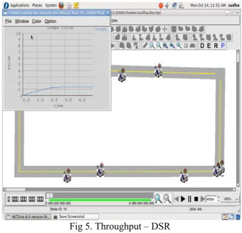
5.6 NCTUns: NCTUns is a software tool that integrates user level processes, operating system kernel, and the user level simulation engine into a cooperative network simulation system. It only supports Fedora distribution, it is possible to port it to other Linux distributions such as Ubuntu.
6 .SIMULATION STUDY –AODV,CAR,DSR
Fig 2. Protocol selection – AODV
Its API plays the same role as the system call interface provided by an UNIX operating system kernel. By executing API functions, a protocol module can request services from the simulation engine without knowing the details of the implementation of the simulation engine. These protocols where implemented using this simulator and the throughput for them is calculated. From the graph it is found that the throughput is high for CAR when compared to that of the other protocols.
Fig 3. Throughput – AODV
Fig.4 Throughput – CAR
Fig 5. Throughput – DSR
CONCLUSION:
The open issue in VANET routing is then for evaluating these protocols. The research direction is that as VANET routings are advancing and becoming mature, many of the underlying assumptions and technologies will need to become mature as well so that much validity can be given to the benefits of these routing protocols. It not only depends on the Protocol but also the simulation environment. The performance of these protocols is also based on the factors such as overhead, packet delay, throughput etc.
REFERENCES
1. S. Yamada, “The strategy and deployment plan for VICS,” IEEE
Communication, vol. 34, no. 10, pp. 94–97, 2006.
2. D. Reichardt, M. Miglietta, L. Moretti, P. Morsink, and W. Schulz,“Cartalk 2008 – safe and comfortable driving based upon
inter-vehiclecommunication,”in Proc. IEEE IV’08.
http://www.cartalk2008.net, Jun 2008, pp. 545–550. 3. N. on Wheels, “www.network-on-wheels.de.” 4. C. C. Consortium, “www.car-2-car.org.”
5. R Manoharan, P Ajit Jose Sylvester and M Ramprasath, “A Robust
Routing Protocol forVANETs using Cellular Automata
International Journal of Recent Trends in Engineering and Technology, Vol. 3, No. 2, May 2010.
6. Thomas D.C. Little and Ashish Agarwal, “An Information
Propagation Scheme for VANETs”,Proceedings of the 8th
International IEEE Conference on Intelligent Transportation Systems,Vienna, Austria, September 13-16, 2005.
7. Gayathri Chandrasekaran, “VANETs: The Networking Platform for
Future Vehicular Applications”, Department of Computer Science,
Rutgers University.
8. R. Mangharam, D. Weller, R. Rajkumar, P. Mudalige, and F. Bai,
“Groovenet: A hybrid simulator for vehicle-to-vehicle networks,” in
Mobile and Ubiquitous Systems - Workshops, 3rd Annual International Conference , 2006.
9. Rakesh Kumar, Mayank Dave, “ A Comparative Study of Various
Routing Protocols in VANET”, IJCSI International Journal of
Computer Science Issues, Vol. 8, Issue 4, No 1, July 2011.
10. C.Perkins, “IP Mobility support for IPv4,” Internet Engineering Task Force (IETF), RFC-3344, 2002.
11. D. Johnson, C. Perkins, and J. Arkko, “Mobility Support in IPv6,”Internet Engineering Task Force (IETF), RFC-3775, 2004. 12. H. Soliman, C. Castelluccia, K. E. Malki, and L. Bellier,
13. V. Devarapalli, R. Wakikawa, A. Petrescu, and P. Thubert, “Network Mobility (NEMO) Basic Support Protocol,”Internet Engineering Task Force (IETF), RFC-3963, 2005.
14. IEEE 802.11: Part11: Wireless LAN Medium Access Control (MAC) and Physical Layer (PHY) Specifications.
15. Kuan-Lin Chiu, Ren-Hung Hwang, Yuh-Shyan Chen, "A Cross Layer Fast Handover Scheme in VANET," IEEE International Conference on Communications (IEEE ICC 2009), Dresden, Germany, June 14-18, 2009.
16. R.-H. Hwang and K.-L. Chiu. Communication Framework for Vehicle Ad Hoc Networks on Freeways. in Preparation
17. Toshiya Okabe, Takayuki Shizuno, Tsutomu Kitamura, “Wireless LAN Access Network System for Moving Vehicles,”10th IEEE Symposium on Computers and Communications (ISCC05), La Manga del Mar Menor. June 2005.
18. Pack, S. ,Choi, Y. , "Fast handoff scheme based on mobility Prediction in public wireless LAN systems", Communications, IEEE Proceedings, Volume 151, Issue 5, 24 Oct, 2004.
19. V. Devarapalli, R. Wakikawa, A. Petrescu, and P. Thubert, “Network Mobility (NEMO) Basic Support Protocol,” Internet Engineering Task Force (IETF), RFC-3963, 2005.
20. T. Arnold, W. Lloyd, and J. Zhao,“IP Address Passing for VANETs,”vol. IEEE International Conference on Pervasive Computing and Communications (PERCOM), Hong Kong, pp. 70-79,March 2008.
21. V. Bychkovsky, B. Hull, A. Miu, H. Balakrishnan, and S. Madden. A measurement study of vehicular Internet access using in situ wi-fi networks. In ACM MobiCom’06, pages 50–61, 2006.