Dc/Dc Converter Fed With Dc Motor
Phase Shift Control Scheme for Modular
Multilevel
Mr. CH RAMKIM-tech Student Scholar
Department of Electrical & Electronics Engineering, lords institute of engineering & technology 500008(Dt); Telangana, India. Email:[email protected]
MR.RAMAKRISHNA Assistant Professor
Department of Electrical & Electronics Engineering, lords Engineering College, hyderabad;
500008 (Dt); Telangana, India. Email:[email protected] .
Abstract-Dc-based distributions and dc-based micro grids are recognized as the promising answers for future brilliant smart grid because of their reasonable points of interest of adaptability for photovoltaic and fuel cells interface, without frequency stability, high change proficiency, and simple system control. Modular Multilevel converter is speaks to a rising topology with adaptable innovation and high voltage and force ability is conceivable. The (MMC) Modular multilevel converters depend on falling of half scaffold converter cells and combine of low switching frequency and low harmonic interface. They can be designed for high operating voltages without direct series connection of semiconductor element. By using the full bridge modules in series the high switch voltage stress in the primary side is reduced. The principle of the phase-shift-controlled three-level dc/dc converter, and the modular multithree-level dc/dc converters, by integrating the full bridge converters and three-level flying capacitor circuit, are investigated in this paper. The proposed concept is implemented to control of DC motor using modular multilevel dc-dc converter using
MATLAB/SIMULINK software.
Index Terms— I\p voltage auto balance, dc/dc modular multilevel converter (MMC), phase-shift control scheme. (ZVS)Zero-voltage switching, DC motor.
I. INTRODUCTION
DC motors available from nearly 100 years. The first electric motors were designed and built for operation of using dc power. AC motors are mainly used in industry purpose for high speed operation. AC motors because they are smaller, lighter, less expensive, no maintenance comparing to their DC counter parts, the latter are still used. The main reasons for why we are that they exhibit wide speed range, very good speed regulation, starting and accelerating torques in excess of 400% of rated, complex control less and usually less expensive drive. In now a day’s Dc motors are used in several applications. The main applications are industrial production and processing of paper pulp, textile industries, and electric vehicles (EV) propulsion and in transportation of public like as trolley and metro. And other so many sectors. These motors are controlling is main thing so we are usually made of power electronics devices, such as
DC drives and their simplicity, ease of application, reliability and favorable cost have been a backbone of the industrial applications.
Other way to classify DC motor drives is classified according to the type of the converter which is utilized in order to control the speed and the torque of the DC motor ([2]-[4]). When a modular multi level inverter (single phase or three phases) is used the respective category is called Controlled inverter-Fed DC Motor Drive. In case that a DC to DC converter is used the respective category is called as chopper Fed DC Motor Drive. These two categories are further subdivided into two types. They are non-generative and generative drives.
In the literature so many different type of converters have been presented and analyzed in whose operation is based on controlled rectifier circuits, single or three phase of DC-AC converters ([2]-[9]).The manufacturing of efficient semiconductor switches led to improvement of converters which receive input DC voltage, and operating at relatively high frequency, exhibiting high response speed are used to control DC motors ([2]. In order to increase further the switching frequency of these DC-DC converters and diminish the ripple current, especially in case of low inductance DC motors, but also to reduce more the size, weight and volume of the overall drive, soft switching DC-DC converters have been developed . These converters initially have been proposed for switched mode power supplies (SMPS) [11], but they do not be directly applied to dc motors. Dc motors are used to improve the speed drives and position of control applications..The Dc motors speeds are below the base speed can be controlled by armature-voltage control. Speeds. And the motor above the base speed are obtained by field-flux control. The speed control method is and less expensive compare the AC motors. The main cases are DC motors are preferred in a wide speed range control is required. The DC choppers are also providing variable dc output voltage from a fixed dc input voltage.
The derivation process of the proposed modular multilevel dc/dc converters is discussed in this section. It is well known that the neutral-point-clamped (NPC) converters and flying capacitor-based converters are the major multilevel topologies for the voltage and high-power applications. For the conventional NPC converters with pulse width modulation control, the abnormal operation condition, such as the mismatch in the gate signals, may cause the voltage imbalance of the input capacitors. Therefore, the converter reliability is impacted. Furthermore, the phase-shift control scheme is not suitable for the conventional NPC converters, which leads to large switching losses. Fortunately, by inserting a small flying capacitor parallel connected with the clamping diodes, the input capacitor voltages are automatically shared because the flying capacitor can be directly parallel with the series input capacitors alternatively.
III. OPERATION PRINCIPLE AND INPUT VOLTAGE AUTOBALANCE MECHANISM For the secondary side of the derived modular multilevel dc/dc converters, the current-type wave rectifier, full-bridge rectifier, current doubler rectifier, and other advanced current-type rectifiers can be employed. In this section, the widely adopted current-type full-wave rectifier is applied as an example to explore the circuit performance of the proposed modular multilevel configuration, which is illustrated in Fig. 1. In the primary side, the capacitors C1and C2are used to split the high input voltage, S11−S14are the power switches of the top full-bridge module, S21−S24form the bottom full-bridge module,Cs11−Cs24are the parasitic capacitors of the power switches, and Llk1and Llk2 are the leakage inductors of the transformersT1andT2, respectively. In the secondary side, Do11, Do12, Lf1, and Co1 are for the top full-bridge module and Do21, Do22, Lf2, and Co2 are for the bottom full-bridge module. ip1, ip2, iDo11, iDo12, iDo21, and iDo22are the primary and secondary currents through the windings of the transformers with the defined direction in Fig. 1. And is1and is2 are the filter inductors currents.
Dc motor
Fig.1. Proposed circuit is Modular Multilevel Dc/Dc Converter (MMC) with Input Voltage Auto Balance Ability and fed DC Motor.
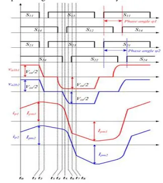
Fig.2. Key waveforms of the proposed converter
A. Operation Analysis
The phase-shift control scheme is employed in the proposed converter to realize the ZVS performance of all the power switches, where S11, S13, S21, and S23 are the leading-leg switches and S12, S14, S22, and S24 are the lagging-leg switches. The key waveforms of the proposed converter are shown in Fig. 2. For the top full-bridge module, S11 and S13 act with 0.5 duty cycle complementarily with proper dead time td, so as for the switches S12 and S14. The phase-shift angle between the leading and lagging switch pairs is defined asleading and lagging switch pairs is defined as ϕ1.
The gate signal pattern of the bottom full-bridge module is similar to that of the top full-bridge module with the phase-shift angle ϕ2. Meanwhile, the leading switches pair S11 andS13 turns ON and OFF simultaneously with the switch pair S21 and S23, while the phase-shift angles ϕ2. Mean while, the ϕ2. Meanwhile, the ϕ1 and ϕ2 are decoupled control freedoms for the output voltage regulation.
and operation, only the first eight stages are analyzed as follows.
Stage 1 [t0,t1]:Before t1, the switches S11,S14,S21, and S24are in the turn-on state to deliver the power to the secondary side. The output diodes Do11 and Do21 are conducted and the output diodes Do12 and Do22 are reverse biased. The flying capacitor Cf is in parallel with the input divided capacitor C1 to make VCf equal toVC1.
(1)
(2)
Dc motor
Stage 2 [t1,t2]:At t1, the turn-off signals of the switches S11and S21are given. ZVS turn off for these two switches are achieved due to the capacitors Cs11 and Cs21. Cs11 andCs21 are charged andCs13 andCs23 are discharged by the primary currents.
Dc motor
Stage3 [t2,t3]:At t2, the voltages of Cs13 andCs23 reach 0 and the body diodes of S13 and S23 are conducted, providing the ZVS turn-on condition for S13 and S23. The flying capacitor Cf is changed to be in parallel with the input divided capacitor C2. The primary currents are derived by
(3)
(4)
Dc motor
Stage 4[t3,t4]:At t3,S14turns off with ZVS.Cs14is charged andCs12 is discharged, leading to the forward bias of Do12; hence, the secondary currentis1 circulates freely through both Do11andDo12. ip1is regulated by
(5)
Dc motor
Stage 5 [t4,t5]:At t4, the turn-off signal of S24comes. ZVS turn-off performance is achieved forS24. Similar to the previous time interval, Do21 and Do22 conduct simultaneously, thus leading to the transformer T2 short-circuit.ip2is regulated by
(6)
Dc motor
(7)
Dc motor
Stage 7 [t6, t7]: At t6,ip1 decreases to 0 and increases reversely with the same slope throughS12 andS13. Cs22 is discharged completely and the anti parallel diode ofS22conducts. ip2 declines rapidly duo to half-input voltage across the leakage inductor Llk2.ip2is given by
(8)
Dc motor
Stage 8 [t7, t8]: At t7, ip2 decreases to 0 and increases reversely through S22 and S23. The current through the output diodeDo11 decreases to 0 and turns off. The output diode Do21 turns off after t8, and then a similar operation works in the rest stages.
B. Input Voltage Auto balance Mechanism
The input voltage imbalance is one of the major drawbacks for most multilevel converters and ISOP converters, which is mainly caused by the asymmetry of the component parameter difference and the mismatch of control signals. It has been carried out that the transformer turns ratio difference (N), leakage inductance distinction (Llk), and phase-shift angle mismatch
(
ϕ) the are the main reasons for the input voltage imbalance in the steady state for the ISOP phase-shift-controlled converters. The effect of these factors is summarized in Table I, which shows that N1 >N2 or Llk1 >Llk2 or ϕ1 >ϕ2 leads to the voltageleads to the voltage VC1on the top input capacitor C1higher than the voltageVC2on the bottom capacitor C2 and vice versa. As the parameter difference increases, thevoltage gap betweenVC1and VC2 increases correspondingly.
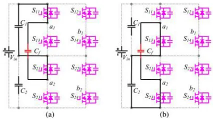
The input voltage auto balance mechanism of the proposed modular multilevel dc/dc converter is displayed in Fig. 6 and detailed elaborated as follows. According to the steady operation of the proposed converter, for the leading-leg switches, the switchesS11andS21have the same time sequence and the switchesS13 andS23 are operated synchronously. WhenS11 andS21 are turned ON, S13 and S23 are turned OFF accordingly, and the flying capacitor Cf is connected in parallel with the top input capacitor C1 as plotted in Fig. 3(a). This makes VCf equal toVc1. In the same way, as given in Fig. 3(b), the flying capacitor Cf is in parallel with the bottom input capacitor C2, whenS13and S23are in turn-on state. This denotes that VCf andVc2 are the same. The connection of Cf with C1 or C2 alternates with high switching frequency, which leads to the voltages on both the input capacitors automatically shared and balanced.
It is important to point out that the flying capacitor does not connect with the lagging-leg switches directly. As a result, the operation of Cf hardly affects the states of the lagging-leg switches. Then, both the two phase-shift angles ϕ1 and ϕ2can be taken as control freedoms to regulate the output voltage.
Fig.3. Input voltage auto balance mechanism: (a)Cf in parallel withC1
and(b)Cf in parallel withC2
IV. DC MOTOR
DC motors are preferred where wide speed range control is required. Phase controlled converters provide an adjustable dc voltage from a fixed ac input voltage. DC choppers are also providing dc output voltage from a fixed dc input voltage. The use of phase controlled rectifiers and dc choppers for the speed control of dc motors modern industrial controlled applications. DC drives are classified into the following methods:
A.DC Motor Control System
loop. The feedback signal of speed is derived from a tacho generator. Although alternatively an approximation of the motor speed can be derived by feeding back a signal proportional to the motor voltage. The Position criticism can be incorporated for servo applications by utilizing a position encoder on the engine shaft. The pace input circle contrasts the taco yield voltage and a pace reference signal. The voltage signal blunder gives the present reference command. In that present summon sign is contrasted and the genuine engine current in the internal control circle. In this control circle incorporates the current cutoff setting which shields that engine and the device from over streams. On the off chance that the controller requests a substantial pace change then the present interest is kept up beneath the greatest level by this present farthest point setting. Motoring or recovering operation is distinguished in circuit straightforwardly from the extremity of the blunder voltage flag and used to figure out if it is the base or top MOSFET and which is controlling the current. The motoring recovering rationale circuit incorporates a few hysteresis to guarantee that control does not waver between the motoring and recovering modes at low engine currents.There are conceivable methods for controlling so as to control engine current the changing successions to the fundamental Power Metal oxide semiconductor (MOS) device. In resistance band control the engine current is contrasted and the reference sign and a permitted current swell resilience. Amid motoring operation the real current is more prominent than the permitted greatest estimation of the resistance band. At that point the yield comparator turns off the door drive to the force MOSFET in this manner the permitting engine current to fall. at the point when the comparator walks out on The present then free wheels until it achieves the lower furthest reaches of the resilience band, .by Using this present control procedure the powerful variable, depending up on the rate at which the armature current changes, however the top to crest current swell in the framework is steady. by utilizing Beat width regulation (PWM) system current control Alternately the device can be exchanged a steady recurrence . Here the present blunder contrasted and altered recurrence triangular wave and the comparator yield is then used to give the sign to the principle exchanging device. Whenever the blunder sign is not exactly the triangular transporter then the gadget is exchanged off. At the point when the blunder sign is more prominent than triangular wave then the power gadget is switched on.
.
Fig.4. DC drives system - schematic arrangement.
B.APPLICATION OF DC SHUNT MOTOR
1. For a given field current in a shunt motor, the speed drop from no-load to full load is invariably less than 6% to 8%. In view of this, the shunt motor is termed as a constant speed motor. Therefore, for constant speed drives in industry DC shunt motors are employed.
2. When constant speed service at low speeds is required, DC shunt motors are preferred over synchronous motors. 3. When the driven load requires a wide range of speed control, both below and above the base speed, a DC shunt motor is employed.
4. DC shunt motor can be used as a separately excited motor, if the field winding is disconnected from armature and connected to an external voltage source.
V. SIMULATION RESULTS
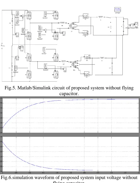
Fig.5. Matlab/Simulink circuit of proposed system without flying capacitor.
Fig.7. Simulation Waveform Of Proposed System Output Voltage Without Flying Capacitor.
Fig.8.Matlab/Simulink circuit of proposed system with flying capacitor.
Fig.9.Primary voltage and current.
(a)
(b)
Fig.10. simulation results of ZVS operation: (a) ZVS operation for S11 and (b) ZVS operation for S14 .
Fig.11.simulation waveform of proposed system input voltage with flying capacitor.
Fig.12.Matlab/Simulink Circuit of Dc Motor System with Flying Capacitor.
Fig.14.Matlab/Simulink Circuit for Dc Motor System without Capacitor.
Fig.15.Simulation Waveform of Armature Current, Speed and Torque for Dc Motor System without flying Capacitor.
VI. CONCLUSION
In this paper, a novel phase-shift-controlled modular multilevel dc/dc converter is proposed and analyzed for the high input voltage dc-based systems. Due to the inherent flying capacitor, which connects the input divided capacitors alternatively, the input voltage is automatically shared and balanced without any additional power components and control loops. Consequently, the switch voltage stress is reduced and the circuit reliability is enhanced. By adopting the phase-shift control scheme, ZVS soft-switching performance is ensured to reduce the switching losses. The modular multilevel dc/dc converter concept can be easily extended to N-stage converter with stacked full-bridge modules to satisfy extremely high-voltage applications with low-high-voltage-rated power switches. In this paper High Input Voltage Based Dc Motor with Phase Shift Controlled Modular Multilevel Dc/Dc Converter.
REFERENCES
[1] H. Kakigano, Y. Miura, and T. Ise, ―Low-voltage bipolar-type DC microgrid for super high quality distribution, ‖IEEE Trans. Power Electron., vol. 25, no. 12, pp. 3066–3075, Dec. 2010.
[2].S. Anand and B. G. Fernandes, ―Reduced-order model and stability analysis of low-voltage DC micro grid,‖ ] IEEE Trans. Ind. Electron. vol. 60, no. 11, pp. 5040–5049, Nov. 2013
[3] S. Anand and B. G. Fernandes, ―Optimal voltage level for DC micro grids,‖ in Proc. IEEE Conf. Ind. Electron., 2010, pp. 3034–3039. [4] D. Salomonsson, L. Soder, and A. Sannino, ―An adaptive control system for a DC microgrid for data centers,‖ IEEE Trans. Ind. Appl., vol. 44, no. 6, pp. 1910–1917, Nov./Dec. 2008.
[5] K. B. Park, G. W. Moon,, and M. J. Youn, ―Series-input series-rectifier interleaved forward converter with a common transformer reset circuit for high-input-voltage applications,‖IEEE Trans. Power Electron., vol. 26, no. 11, pp. 3242–3253, Nov. 2011.
[6] T. Qain and B. Lehman, ―Coupled input-series and output-parallel dual interleaved flyback converter for high input voltage application,‖ IEEE Trans. Power Electron., vol. 23, no. 1, pp. 88–95, Jan. 2008. [7] C. H. Chien, Y. H. Wang, B. R. Lin, and C. H. Liu, ―Implementation of an interleaved resonant converter for high-voltage applications,‖ Proc. IET Power Electron., vol. 5, no. 4, pp. 447–455, Apr. 2012.
[8] C. H. Chien, Y. H. Wang, and B. R. Lin, ―Analysis of a novel resonant converter with series connected transformers,‖Proc. IET Power Electron., vol. 6, no. 3, pp. 611–623, Mar. 2013.
[9].W. Li, Y. He, X. He, Y. Sun, F. Wang, and L. Ma, ―Series asymmetrical half-bridge converters with voltage auto balance for high input-voltage applications,‖ IEEE Trans. Power Electron. vol. 28, no. 8, pp. 3665– 3674, Aug. 2013..
[10] T. T. Sun, H. S. H. Chung, and A. Ioinovici, ―A high-voltage DC-DC converter with Vin/3—Voltage stress on the primary switches,‖ IEEE Trans. Power Electron., vol. 22, no. 6, pp. 2124–2137, Nov. 2007. [11] T. T. Sun, H. Wang, H. S. H. Chung, S. Tapuhi, and A. Ioinovici, ―A highvoltage ZVZCS DC-DC converter with low voltage stress,‖ ] IEEE Trans. Power Electron., vol. 23, no. 6, pp. 2630–2647, Nov. 2008. [12].H. Wang, H. S. H. Chung, and A. Ioinovici, ―A class of high-input low output voltage single-step converters with low voltage stress on the primary-side switches and high output current capacity, ‖ ] IEEE Trans. Power Electron. vol. 26, no. 6, pp. 1659–1672, Jun. 2011.
[13] J. R. Pinheiro and I. Barbi, ―The three-level ZVS PWM converter—A new concept in high voltage DC-to-DC conversion,‖ in Proc. IEEE Int. Conf. Ind. Electron. Control Instrum. Autom., 1992, pp. 173–178.
[14] R. Xinbo, L. Zhou, and Y. Yan, ―Soft-switching PWM three-level converters, ‖IEEE Trans. Power Electron., vol. 16, no.5, pp. 612–622, Sep. 2001.