Optimizing the Robot’s Path Using Dijkstra
Algorithm
Bharath Uppalancha
1, Kranthi
2P.G. Student, Department of Mechanical Engineering, VNR Vignana Jyothi Institute of Engineering & Technology , Bachupally, Nizampet, Telangana, India1
Assistant Professor, Department of Mechanical Engineering, VNR Vignana Jyothi Institute of Engineering & Technology ,Bachupally, Nizampet, Telangana , India2
ABSTRACT: Automobile routing problem (ARP) referrers to optimizing solutions in vehicle emergency, transportation, distribution and logistics industry. In this project we implement a frame work to update the best short route. By implementation of the classified algorithms proposed by Dijkstra’s. We are simulating the results with Matlab platform, the efficiency of Dijkstra algorithm in transportation routes in which the best route should be updated.
KEYWORDS:robotics, MATLAB, LPC2148, path planning, dijkstra algorithm, arm7.
I. INTRODUCTION
Finding the shortest route between two locations in road networks is a tricky task in automobile routing area and related transportation. Selecting a appropriate planning algorithm from the numerous algorithm proposed is a key issue in many transportation applications involving real road transportation.
Therefore, those algorithms should be extended in order to take into account these dynamic parameters and update the chosen shortest path accordingly.
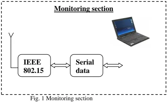
Fig. 1 Monitoring section
Monitoring section
Serial
data
Transf
er unit
Pro
IEEE
802.15
.4
Protoc
ol
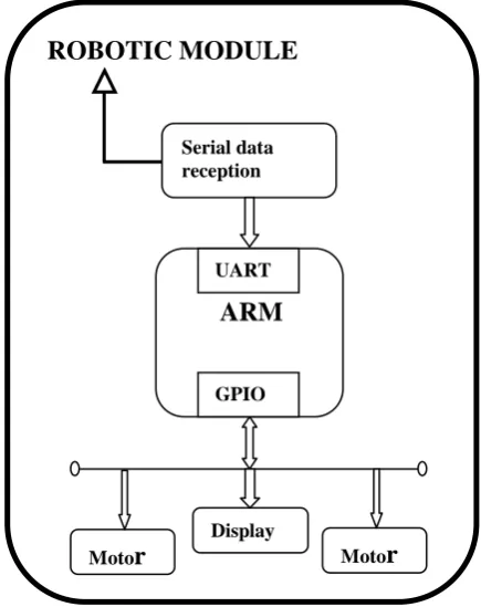
Fig. 2 Block diagram of robotic module
II. HARDWAREDESIGNINTERFACING WITH LPC2148
a) LCD DISPLAY INTERFACING:
An LCD consists of two glass panels, with the liquid crystal material sand witched in between them. The inner surface of the glass plates are coated with transparent electrodes which define the character, symbols or patterns to be displayed polymeric layers are present in between the electrodes and the liquid crystal, which makes the liquid crystal molecules to maintain a defined orientation angle. One each polarisers are pasted outside the two glass panels. These polarisers would rotate the light rays passing through them to a definite angle, in a particular direction. When the LCD is in the off state, light rays are rotated by the two polarisers and the liquid crystal, such that the light rays come out of the LCD without any orientation, and hence the LCD appears transparent. When sufficient voltage is applied to the electrodes, the liquid crystal molecules would be aligned in a specific direction. The light rays passing through the LCD would be rotated by the polarisers, which would result in activating / highlighting the desired characters. The LCD’s are lightweight with only a few millimeters thickness. Since the LCD’s consume less power, they are compatible with low power electronic circuits, and can be powered for long durations.
Procedure for programming LCD in 8 bit Mode:
1. Select the I/O Pins Required to interface LCD (RS, RW, EN, D0, D1, D2, D3, D4, D5, D6, and D7) to connect to the port.
2.Write a function to apply command to LCD. By making RS Low, RW Low and EN High to Low. Apply the data to the data lines.
6. In main function first initialize the LCD By Using the Commands and then apply your data to LCD.
b) CONFUGIRATION OF SERIAL COMMUNICATION:
UART0 Transmit Holding Register (U0THR - 0xE000 C000, when DLAB = 0, Write Only):
The U0THR is the top byte of the UART0 TX FIFO. The top byte is the newest character in the TX FIFO and can be written via the bus interface. The LSB represents the first bit to transmit.
The Divisor Latch Access Bit (DLAB) in U0LCR must be zero in order to access the U0THR. The U0THR is always Write Only
UART0 Receiver Buffer Register (U0RBR - 0xE000 C000, when DLAB = 0, Read Only):
The U0RBR is the top byte of the UART0 Rx FIFO. The top byte of the Rx FIFO contains the oldest character received and can be read via the bus interface. The LSB (bit 0) represents the “oldest” received data bit. If the character received is less than 8 bits, the unused MSBs are padded with zeroes.
The Divisor Latch Access Bit (DLAB) in U0LCR must be zero in order to access the U0RBR. The U0RBR is always Read Only.
UART0 Divisor Latch Registers (U0DLL - 0xE000 C000 and U0DLM-
0xE000 C004, when DLAB = 1):
The UART0 Divisor Latch is part of the UART0 Fractional Baud Rate Generator and holds the value used to divide the clock supplied by the fractional presale in order to produce the baud rate clock, which must be 16x the desired baud rate. The U0DLL and U0DLM registers together form a 16 bit divisor where U0DLL contains the lower 8 bits of the divisor and U0DLM contains the higher 8 bits of the divisor. A 0x0000 value is treated like a 0x0001 value as division by zero is not allowed. The Divisor Latch Access Bit (DLAB) in U0LCR must be one in order to access the UART0 Divisor Latches.
Fig: 3 LCD display
Procedure for Initializing Programming UART:
1. Initialize UART by selecting the character length and stop bits by using U0LCR Register and Enable DLAB bit to load baud rate values in U0DLL & U0DLM Registers (Select 8 bit character and 1 stop bits and make DLAB bit high).
2. Load values into U0DLL and U0DLM By using Given Formulas.
Procedure for Transmitting a character Using UART:
1. Initialize UART Using Procedure 1.
2. To Transmit a Character place character in U0THR Register
3. Wait for the Transmitter Empty (TEMT) Flag in U0LSR Register.
Procedure for Transmitting a character Using UART:
1. Initialize UART Using Procedure 1.
2. Wait for the Receive Data Ready (RDR) Flag in U0LSR Register.
3. Return character from Receive Buffer Register (U0RBR).
c) DIJKSTRA’S ALGORITHAM:
Dijkstra's algorithm - is a solution to the single-source shortest path problem in graph theory. Works on both directed and undirected graphs.
However, all edges must have nonnegative weights. Approach: Greedy
Input: Weighted graph G={E,V} and source vertex v∈V, such that all edge weights are nonnegative
Output: Lengths of shortest paths (or the shortest paths themselves) from a given source vertex v∈V to all other vertices.
Implementations and Running Times
The simplest implementation is to store vertices in an array or linked list. This will produce a running time of O(|V|^2 + |E|) For sparse graphs, or graphs with very few edges and many nodes, it can be implemented more efficiently storing the graph in an adjacency list using a binary heap or priority queue. This will produce a running time of O((|E|+|V|) log |V|).
Applications of Dijkstra's Algorithm
- Traffic Information Systems are most prominent use - Mapping (Map Quest, Google Maps)
Fig: 4 Google maps
D) L293D:
Maximum current i(max) that can be sourced or drain from a LPC2148 microcontroller is nearly 15 mA at 5v. A DC Motor need currents very much more than that and it need voltages 9v, 24v etc, depending upon the type of motor. Because of these reasons we cannot interface a DC Motor directly to microcontroller.
Future scope:
Dijkstr a’s Algorithm is used to find the shortest path from one node to another node in a graph.Dijkstra’s algorithm is also known as a single source shortest path algorithm.
Fig 5: Robotic Module
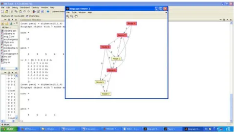
Fig 6: Result of shortest path from node1 to node4
III. CONCLUSION
REFERENCES
[1] Shivani sanan, Leena jain, Bharti kappor : Shortest Path Algorithm, International Journal of Application or Innovation in Engineering & Management (IJAIEM) , vol 2 , issue 7, July 2013, page 316-320.
[2] “Google Cars drive themselves in Traffic”, J. Markoff - The New York Times, 2010 - bngumassd.org
[3] Zhanying zhang and ziping zhao : A Multiple Mobile Robots Path Planning Algorithm Based On A-star And Dijkstra Algorithm, International Journal Of Smart Home, Vol.8 ,2014, page 75-86.
[4] “A Method for Shortest Path Search using Extended Dijkstra’s Algorithm”, IEEE International Conference on System, Man and Cybernetics, 2000
[5] Yuan Yuan, Dingwei Wang :path selection model algorithm for emergency logistics management, computer & Industrial Engineering 56,2009 , page 1081-1094.
[6] National Highway Traffic Safety Administration,” Automotive Collision Avoidance Systems (ACAS) Final Report”. August 2000.
[7] “Proof of a modified Dijkstra's algorithm for computing shortest bundle delay in networks with deterministically time-varying links”, Lee, Fraser.S, IEEE Xplore 2011
[8] A.R. Soltani, H.Tawfik, J.Y. Goulermas, T. Fernando : path planning in construction sites: performance evalution of the Dijkstra, A* and GA search algorithms, Advanced Engineering Informatics 16(2002), page 291-303.
[9] T.Imielinski and J.C. Navas, “GPS-Based Geographic Addressing, Routing, and Resource Discovery,” Commun. ACM, vol. 42, no. 4 Apr. 1999 [10]s.pavani, m.kezia aruna jyothi : shortest path finding based architecture for vehicle navigation:
[11]Q.Xu, R.Sengupta and D.Jiang, “Design and Analysis of Highway Safety Communication Protocol in 5.9Ghz DSRC,” Proc. IEEE VTC vol.57, no.4, 2003, pp. 2451-2455
[12]A.R. soltani, H.tawfik, T.fernando path planning in construction sites: performance evaluation of Dijkstra ,A* and GA search algorithm.
BIOGRAPHY
U Bharath kumar received his B.TECH degree in Mechanical Engineering from Hi-Tech college of Engineering and Technology, Himayathnagar,Rangareddy (Dist), affiliated to JNTUH. He is currently pursuing M.Tech Cad/Cam in VNR vignana jyothi college of Engineering and Technology (Autonomous), Bachupally, Rangareddy (Dist), affiliated to JNTUH.
M.Kranthi received her B.tech degree in Mechanical Engineering from Syed Hassim college in 2006 and received her M.Tech degree from Osmania University in Mechanical Engineering in the year 2008. She has 5 years of teaching experience working as
Assistant professor in the department of Mechanical in VNR vignana jyothi college of Engineering and Technology (Autonomous), Bachupally, Rangareddy (Dist), affiliated to JNTUH.