Mamunur Rashid Akand and Reihaneh Safavi-Naini University of Calgary, Calgary, AB, Canada {mdmamunurrashid.akan,rei}@ucalgary.ca
Abstract. Location information has wide applications in customization and personalization of services, as well as secure authentication and ac-cess control. We introducein-Region Authentication (inRA), a novel type of authentication, that allows a prover to prove to a set of cooperating verifiers that they are in possession of the correct secret key, and are inside a specified (policy) region of arbitrary shape. These requirements naturally arise when a privileged service is offered to registered users within an area. Locating a prover without assuming GPS (Global Posi-tioning System) signal however, incurs error. We discuss the challenge of designing secure protocols that have quantifiable error in this setting, define and formalize correctness and security properties of the protocols, and propose a systematic approach to designing a family of protocols with provable security where error can be flexibly defined and efficiently minimized. We give a concrete instance of this family that starts with two verifiers, prove its security and evaluate its application to four dif-ferent policy regions. Our results show that in all cases false acceptance and false rejection of below 6% can be achieved. We compare our results with related works, and propose directions for future research.
Keywords: In-region·Distance Bounding·Authentication.
1
Introduction
security has been formalized, and protocols with provable properties have been proposed [4, 3, 21, 9]. Successful authentication allows the user to perform a priv-ileged action, e.g., open the car door [11], or access a special system resource.
In this paper we consider access control with respect to a region R, that is called policy region. The user has to “prove” to the verifier(s) that, (i) they have the secret key ku, and (ii) they are within the region R. This setting
naturally arises when a privileged service is offered in a regionR. For example a project team in a software development company can access proprietary project information when they are at their workspace. In this setting authentication protocol must prove the conjunction,
U serhas the shared secretku ∧ (U seris in R). (1)
We propose a new authentication system that is calledin-Region Authentication (inRA), that provides proof that the above conjunction holds.
A simplistic solution to prove the conjunction (1) is to use a secure cryp-tographic authentication to allow the user to prove that they know the secret ku, and then use a secure location verification protocol to prove their location.
This solution however will be insecure because, firstly, proving the two clauses separately allows new attacks, for example the prover changing the location in between the two steps, and secondly, secure location verification protocols [18, 7] start with the prover claiming a location, which needs them to access GPS signal. This not only limits application of the protocol to locations where GPS signal is available, but also opens the possibility of GPS spoofing attacks [23].
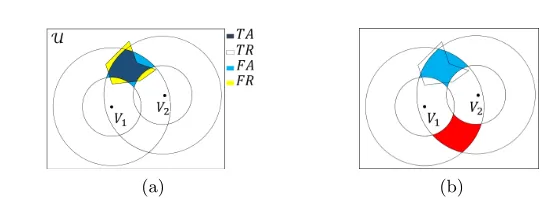
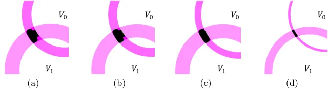
One can combine the two steps when R is a circular region by employing a secure DUB protocol: the verifier of the DUB protocol will be placed at the center of the region and the distance bound will be chosen as the radius of
R (Fig. 1a). The approach works perfectly becauseR is perfectly covered with the circle associated with the boundary of the DUB protocol. For arbitraryR, one can use anapproximate coverby using one or more verifiers (See Fig. 1b and 1c): the prover must prove its distance to the corresponding verifier of each part of the region. This is the approach in [16] to solve the closely related problem of
in-region location verificationwhere the goal is to verify that the prover is within the region,without requiring authentication of the useror quantifying error.
Using multiple verifiers to cover R requires one to determine the verifier configuration, which is specified by (i) the number of verifiers, (ii) their locations, and (iii) their associated distance bounds. Note that the error associated to a configuration does not have an algebraic form and one cannot use traditional optimization methods to find the optimal configuration, and this is true even if the number and location of verifiers are known.
Our work.
(a) (b) (c)
Fig. 1. Location verification for (a) circular region Rthat is perfectly covered by a single verifier placed at the center ofR, (b) arbitrary shaped regionR, a single verifier does not give perfect coverage, and (c) arbitrary shaped region R, multiple verifiers are placed insideR ([16]’s approach), also does not give perfect coverage.
respect to the policy region R. Our security definition formalizes attacks that involve a malicious prover outsideR, an unregistered user insideR, and a collu-sion of a malicious prover and a helper who is insideR. A significant challenge in modelling and achieving security is the possibility of the prover moving be-tween their interactions with different verifiers. Our security model uses ITMs (Interactive Turing Machines) to model the prover and verifiers and does not formalize time (movement of the prover). We assume prover movement will be detected through other mechanisms, and our protocol introduces a mechanism that does that, allowing us to use our security model.
Construction. Armed with this model and definition, we propose a systematic approach to designing inRA protocols for the proof of the conjunction (1) and withquantifiable correctness error, and give an efficient algorithm to minimizing the error (see below). The approach in its basic form uses two verifiers V0 and
V1, and covers the regionR with a pseudo-rectangle (P-rect)R0(V0, V1) that is
formed by two rings centered at the two verifiers (See Figure 2 and Section 3). A ring is formed by a verifier running a DUB protocol followed by aDistance Lower Bounding (DLB) protocol [27] (that guarantees a lower bound on the distance of the prover to the verifier- See Section 2), with the prover. The two verifiers work in tandem, with the second immediately following the first. Verifiers use omnidirectional antennas during the protocol initialization, and use directional antennas for the challenge-response phase.
This basic inRA protocol approximatesR with a P-rect and results in FA and FR. We define the total error as the sum of FA and FR errors and aim at minimizing it. Our approach however can be easily extended to the case that the two types of errors have different significance – See Sec 6.
Minimizing error. For fixed locations of V0 andV1, the total error is a function
error in approximate coverage ofR with a P-rect. The algorithm has complexity O(n3) wherenis the size ofR represented as a point set. This basic algorithm
can be employed multiple times using more verifiers, to increase accuracy. In Section 6 we show that using two P-rects to cover the region reduces the total error by up to 15%. We leave the problem of optimizing the number and the locations of the verifiers as an interesting direction for future work.
Security proof. In our basic protocol (Section 4) we will use a novel approach to detecting movement of the prover during protocol execution, by using each verifier to play the role of an observer for the other verifier’s interaction with the prover. We will then use our security model to prove security against attacks. We discuss how protection against a new attack calledkey splitting attackthat is the result of using a pair of DUB and DLB protocols with two verifiers, can be avoided by using keys shared withV0andV1both, to generate the fast phase
responses to each verifier.
Implementation and experimental results.We implemented the optimization al-gorithm for two verifiers and applied it to four policy regions corresponding to buildings in our University (Section 6). We started with a 640×640 Google Map image of the policy region, and converted it into a binary image for point-set rep-resentation of the policy regions. To achieve higher accuracy, we used two P-rects to cover the policy region. Table 1 summarizes our results. The highest accuracy is obtained for the most regularly shaped rectangular region. In all cases FA and FR range between 0.81% to 5.16%, and 3.89% to 5.58%, respectively.
We compared our approach with the scheme in Sastry et al. [16]. This is the only system with comparable security goals and assumptions. Comparison (Sec. 6) clearly shows superior performance of our approach: [16] uses 5 verifiers to achieve 93% accuracy, and uses informal security analysis, while we use 2 verifiers, achieve 96.4% accuracy, and provide formal security proof.
Extensions. One can define weights for each type of FA and FR error depend-ing on the application, and use optimization approach on the weighted error function. The approach raises numerous interesting open questions such as op-timizing the total error when there are more than two verifiers, and one needs to select their locations and distance bounds. We leave these for future work.
Organization. Section 2 is preliminaries. Section 3 describes our inRA model. Section 4 details the inRA protocol Πrect, and the security analysis of Πrect.
Section 5 provides our approach to minimize error. Section 6 includes our ex-perimental results. Section 7 presents related works and Section 8 concludes the paper. Appendix includes security models of DUB and DLB protocols, and ex-plainserasure sequencethat is used in DLB, and our proofs. Appendix includes security models of DUB and DLB protocols, and explainserasure sequencethat is used in DLB, and our proofs.
2
Preliminaries
round-trip time of a challenge and response is used to estimate distance. The goal of a distance Upper bounding (DUB) protocol is to ensure that a proverP located at distancedP V satisfiesdP V ≤ BU whereBU is a fixed upperbound.
The main attacks on distance bounding protocols are, i) Distance fraud at-tack: a far away dishonest prover tries to claim a shorter dP V and be accepted
byV; ii) Mafia fraud attack: an external attacker uses the communication of an honest prover to get accepted by the verifier, and iii) Terrorist attack (also known as collusion attack): a dishonest prover gets help from a helper that is close to the verifier, to get accepted by the verifier. A number of formal security mod-els that capture above attacks, and protocols with provable security have been proposed [21, 9]. Secure DUB protocols are vulnerable to distance enlargement attack but not to distance reduction attack [5].
The goal of distance lower bounding (DLB) protocols [27] is the converse: a prover wants to prove that their distance to the verifier is larger than a given bound. Zheng et. al.[27] showed that one cannot simply use DUB protocols to guarantee a lower bound on the distance of the prover. They proposed a security model for DLB that is inline with the DUB security model, and constructed a DLB protocol with provable security in their model. Our construction of inRA protocolΠP rectuses DLB protocol together with a DUB protocol.
Maximum Subarray Problem. Optimizing P-rect uses maximum subarray problem (MSP), first proposed in [12]. The problem is to select a contiguous segment of an array that has the largest sum over all possible array segments. Efficient algorithms for MSP problem have applications in computer vision, data mining and genomic sequence analysis [24, 20, 10]. For a 2D array a[1..m][1..n], the maximum sub-arrayM is given by [2],
M = max
j,h
X
x=i,y=g
a[x][y]|1≤i≤j≤m,1≤g≤h≤n (2)
Solutions have complexity cubic or sub-cubic [19]. To find the P-rect with the lowest total error, or equivalently maximum accuracy, we will use FindOp-timalBounds algorithm (Sec. 4) that uses the extended Kadane’s algorithm [2].
3
In-Region Authentication Systems
Consider a two-dimensional planar connected (path connected) geographic area represented by an array of points, each point representing a geolocation1. Let
U denote the universe of all points of interest, and R ⊂ U, be the policy re-gion. There are multiple parties, each represented by a polynomially bounded Interactive Turing Machine (ITM), and associated with a location loc.
(a) (b)
Fig. 2.(a) The policy regionRis the yellow arbitrary shaped region. The blue (almost) rectangular area is P-rect RΠ for the inRA protocol in Section 4. The dark blue
area ofR is correctly covered. The remaining yellow and blue areas areF RΠ,R and F AΠ,R, respectively. (b) The upper intersection forms Rrect to coverR(blue). The
lower intersection formsR0rect(red), an ambiguous region.
and random coin. This is shown by P(x;rP) ↔V(y;rV), x and y are the
in-puts, rP andrV are the random coins of the two participants, respectively. We
can “enlarge” the experiment to include an adversary’s algorithm, shown as: P(x;rP)↔ A(rA) ↔V(y;rV). This means that an adversaryA is interfering
with the communication between the honest participants.
inRA protocols. LetR be a connected policy region (Fig. 2). The verifying systemconsists of a set of verifiers V ={V0· · ·Vm−1}, with publicly known
lo-cations. Verifiers are trusted to follow the protocol and can communicate among themselves through secure channels to exchange information and coordinate their actions. Verifiers are equipped with directional antennaswhose signals can be received in a conic region of spece that coversR. A proverP with locationlocP,
has shared keys with the verifier setV. The prover is not trusted.
Anin-region authentication protocol is a protocol Π between P and V, at the end of which V outputs OutV = 0 or 1, denoting reject and accept of the
prover’s claim, respectively. Prover does not have an output and soOutV is the
protocol output. The prover’s claim is stated as the conjunction in (1).
DUB protocols can be seen as inRA protocols where the second proposition is,P is within a distance bound from the verifier.
Error and accuracy in inRA protocols.Consider an instance of a protocolΠ between an honest proverP and the verifier set, in the absence of an adversary. Let RΠ ⊂ U denote the set of points u ∈ U that Π will have OutV = 1 .
We define two types of errors for the protocolΠ with respect to the regionR: F AΠ,R andF RΠ,R, denoting false acceptance and false rejection of the protocol
Π, respectively, where, (i)F AΠ,R is theset of locationsthat are inRΠ\ R,2
andF RΠ,R is theset of locationsthat are inR \ RΠ. Accuracy ratio can be
defined as follows [14]:
Accuracy ratio= T AΠ,R+T RΠ,R
T AΠ,R+T RΠ,R+F AΠ,R+F RΠ,R
(3) 2
where T AΠ,R and T RΠ,R denote the true acceptance and true rejection sets,
T AΠ,R is the set of points inR ∩ RΠ and are accepted by the algorithm, and
T RΠ,R is the set of points inU \ {R ∪ RΠ}and are rejected by the algorithm.
Now,Error ratio= 1−Accuracy ratio, and can be expressed as,
Error ratio= F AΠ,R+F RΠ,R
T AΠ,R+T RΠ,R+F AΠ,R+F RΠ,R
(4)
Since U= (T AΠ,R+T RΠ,R+F AΠ,R+F RΠ,R) is constant, to minimize error
one needs to minimize (F AΠ,R+F RΠ,R). In our work we useerrorEΠ,R given
by,
Error: EΠ,R=F AΠ,R+F RΠ,R (5)
Note that one can attach weights to points in F AΠ,R or F RΠ,R to reflect
their importance in a particular application. In this paper we assume the same significance for the two types of errors. ForR=T AΠ,R+F RΠ,R, we can write,
F AΠ,R+F RΠ,R=F AΠ,R+ (R−T AΠ,R)
=R−(T AΠ,R−F AΠ,R).
R is fixed and so minimizing (F AΠ,R+ F RΠ,R) is equivalent to maximizing
(T AΠ,R−F AΠ,R).We say that in ourRcoverage problem, error is minimized
by minimizing (F AΠ,R+ F RΠ,R), or equivalently, accuracy is maximized by
maximizing (T AΠ,R−F AΠ,R). Therefore, we define AccuracyAΠ,R as:
Accuracy: AΠ,R=T AΠ,R−F AΠ,R (6)
Definition 1 (in-Region Authentication). An in-region authentication (inRA) protocolΠ is a tuple Π = (Gen, P,V ={V0· · ·Vm−1},R)where:
1. X ←Gen(1s, rk)is a randomized key generation algorithm that generates a
vectorX ={x0, ..., xm−1} of n secret keys, where xi is the prover’s shared
secret key withVi, andrk denoting the random coins ofGen.sis the security
parameter.
2. P(X;rP), is a ppt.(probabilistic polynomial time) ITM (Interactive Turing
Machine) running the prover algorithm with random inputrP and the secret
key vectorX ={x0, ..., xm−1}.
3. V = (V0, ..., Vm−1) is a set of verifiers, each verifier Vi(xi;rVi) ∈ V is a
ppt. ITM running algorithm with random inputrVi and shared secretxi. We
writeV(X, rV)to denote the set of the verifiers’ algorithms.
4. Ris a set of points corresponding to a contiguous region. This is thepolicy region.
The protocol satisfies the following properties:
– Termination:(∀s) (∀Z) (∀(rk, rV)) (∀locV)if X ←Gen(1s, rk)and
(Z ←→ V(X;rV))is the execution whereZ is any set of prover algorithms,
– p-Completeness:(∀s) (∀(locV, locP))such thatlocP ∈ Rwe have
P r
rk,rP,rV
OutV = 1 :X ←Gen(1 s, r
k)
P(X;rP)↔ V(X;rV)
≥p. (7)
Similar definition of termination and completeness is used for DB prortocols [21, 27, 1].
3.1 inRA Security
We consider a prover, possibly malicious, who may receive help from a helper who is inR but does not have a secret key.
The adversary attempts to prove that their location is insideR (while they are actually outside) and their success chance must be negligible even if they know the shared key. We use a game-based approach in defining security, and define security in terms of the success chance of an adversary in the following security games against a challenger. Each game starts with a setup phase where the challenger sets the keys and locations of participants. This is followed by the adversary corrupting some of the participants (depending on the game), engaging them in a learning phase and finally the attack phase. We omit the details because of space and outline the steps of each game in the definition of each attack. In the following, a dishonest prover is denoted byP∗.
in-Region Fraud (inF). In this attack, a corrupted prover P∗ who has the secret key and is inU \ Rwants to prove that they are insideR.
Definition 2 (inF-resistance).An inRA protocolΠisα-resistant to in-region fraud if(∀s)(∀P∗)(∀locV)such thatlocP ∈ {R ∪/ F AΠ,R}, and(∀rk)we have,
P r
rV
OutV= 1 :
X ←Gen(1s, r k)
P∗(X)↔ V(X;rV)
≤α. (8)
The above definition also captures a special type of attack -in-region hijacking
(follows from a similar type of attack in DB protocols -distance hijacking). A dishonest proverP∗located outsideRuses the inRA communications of unaware honest provers (insideR) to get authenticated as an honest prover.
in-Region Man-in-the-Middle (inMiM).A corrupted participant who does not have a key but is insideR, interacts with multiple proversP’s and the verifier setV, and uses transcripts of these protocols to succeed in the inRA protocol. Definition 3 (inMiM-resistance.). An inRA protocol Π is β-resistant to inMiM attack if, (∀s)(∀m, l, z) that are polynomially bounded, (∀A1,A2) that
are polynomially bounded, for all locations s.t. locPj ∈ {R ∪/ F AΠ,R}, where
j∈ {q+ 1, ..., t}, we have
P r
OutV= 1 :
X ←−Gen(1s, r k)
P1(X), ..., Pq(X)←→ A1←→ V1(X), ...,Vz(X)
Pq+1(X), ..., Pt(X)←→ A2(V iewA1)←→ V(X)
The attacker is a pair of algorithms (A1,A2), whereA1 denotes the learning
phase during which the attacker interacts with the protocol-runs of q provers that can be anywhere, and provides this view to A2 in the second stage of the
attack. Definition 3 is general and captures other attack settings that are tradi-tionally referred to as mafia fraud and impersonation attack, in DB protocols. Mafia fraud is an MiM attack as defined above but without a learning phase. In impersonation attack the attacker uses multiple possibly concurrent interactions with the verifiers to make the verifier output 1.
in-Region Collusion Fraud (inCF).Arguably the strongest attack and in-volves the collusion of a corrupted prover who is inU \ R, and a helper who is inside R. In collusion fraud the assumption is that the corrupted prover does not want their long-term secret key to be learnt by the helper as otherwise the helper would have a better chance to succeed in other attacks individually. The prover however attempts to use the helper’s location to succeed in the attack. In the following definition of rCF-resistance, success of the attacker in inCF im-plies that - the attacker in a MiM attacker as defined above (and realized by the helper), will also succeed.P(∗)(X) denotes honest or dishonest prover.
Definition 4 (inCF-resistance.). An inRA protocol Π is (γ, η)-resistant to collusion fraud if(∀s) (∀P∗) (∀locV0 s.t. locP∗∈ {R ∪/ F AΠ,R} (∀A
CFppt.)s.t.
P r
OutV0= 1 :
X ←−Gen(1s)
P(∗)(x)←→ ACF ←→ V 0(X)
≥γ, (10)
over all random coins, there is a two stage attacker(A1,A2)as defined in MiM
with the additional relaxation that in the learning phase, the attacker can interact with the malicious prover also, such that,
P r
OutV= 1 :
X ←Gen(1s)
P1(∗)(X), ..., Pq(∗)(X)←→ A1←→ V1(X), ...,Vz(X)
Pq+1(X), ..., Pr(X)←→ A2(V iewA1)←→ V(X)
≥η.
(11)
The above definition of inCF captures a widely used attack model for DB protocols, which we call in-Region Terrorist fraud (inTF) in which P∗, with locP∗ ∈ {R ∪/ F AΠ,R}, uses a helper who does not have the secret key, to
suc-ceed in an instance of the protocol.
We do not consider jamming attacks blocking all communication. Asecure inRA protocolprovides security against inF, inMiM and inCF.
4
Pseudo-rectangle (P-rect) Cover Approach to inRA
4.1 Basic (two-verifier) P-rect Approach
Protocol communication.We assume radio signal travel at the speed of light and the round trip time of a challenge and response can provide a reliable es-timate of distance. There are two collaborating verifiers who interact with the prover using,slow communicationthat is used for time-insensitive messages over reliable channels, andfast communicationthat are time sensitive messages that are used for estimating distance and are sent over the physical channel that is noisy. For simplicity, we do not consider noise. Our results however can be easily extended to noisy channels by modifying the protocol parameters (thresholds). Verifiers are equipped with omnidirectional and directional antennas, although in each run of the protocol we require only one of them to use their directional antenna for communication with the prover. Communication between the veri-fiers takes place over a secure and reliable channel and is not time sensitive. P-rectangle. For a fixed pair of verifiers, V0 and V1, with lower and upper
bound pairs,{`V0, uV0},{`V1, uV1}, respectively, a P-rect is defined as the set of pointsx∈ U that satisfy the following inequalities:
d(x, locV0)≤uV0, d(x, locV0)≥`V0, d(x, locV1)≤uV1, d(x, locV1)≥`V1 whered(., .) is the Euclidean distance. Consider the two pairs of concentric cir-cles, centred at locV0 with radii {`V0, uV0} and at locV1 with radii {`V1, uV1}, respectively. The intersection of the four circles defines two P-rects (Fig. 2b).
We denote the two mirrored rectangles byRrect(locV0, locV1, `V0, uV0, `V1, uV1) and R0rect(locV0, locV1, `V0, uV0, `V1, uV1). We useRrect andR
0
rect when
parame-ters are known from the context. These P-rects are formed whenV0andV1each
executes a pair of DUB and DLB protocols with corresponding upper and lower bounds. To distinguish between the two, one of the verifiers can use a directional challenge towards the target region R. The inRA protocol Πrect below uses a
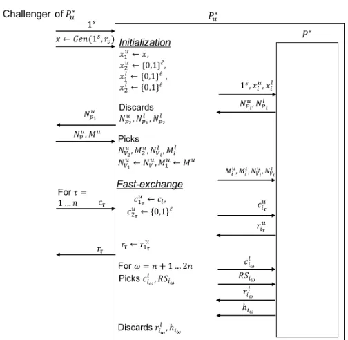
P-rect to coverR. We quantify the error and prove security of this protocol. Protocol Πrect. For given values oflocV0, locV1, `V0, uV0, `V1, uV1, the protocol bounds the prover within-Rrect(locV0, locV1, `V0, uV0, `V1, uV1) (See Fig 3).
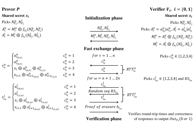
Initialization phase.ProverP and verifiersV0, V1 have shared secretxi, i= 0,1
and security parameterkat the start of the protocol. Prover picks four indepen-dently generated nonces Nl
pi, N
u
pi, i={0,1}, each of lengthk, and sends a pair
of nonces to each verifierVi, i={0,1}. Each verifierVi picks two independently
generated nonces of the same length,Nl vi, N
u
vi, and two random stringsA
u i, Ali,
each of length 2n(2ncorresponds to number of rounds in fast-exchange phase) and calculates, Miu = Aui ⊕fx(Npli, N
l
vi) and M
l
i = A
l
i⊕fx(Npui, N
u
vi). f is a
Pseudo Random Function (PRF).Npui, N
u vi, M
u i , M
l
i are sent to the prover who
decrypts and stores Aui, Ali. These are the response tables of the distance up-per and lower bound challenges for the respective verifiers, in the fast-exchange phase. All communications between the prover and the verifiers use omnidirec-tional antenna in the initialization phase.
Fast-exchange (FE) phase. WLOG assumeV0 starts the FE phase and notifies
V1 to start its FE phase right after sending its last challenge3.
3
Fig. 3. inRA protocolΠrect between a prover and 2 verifiers. In initialization phase
prover and verifiers generate and exchange noncesNl vi, N
u
vi. Fast Exchange phase is 2n
rounds of challenge (cuiτ, c
l
iω) and responses (r
u iτ, r
l
iω) for DUB and DLB. The responses
are calculated using a pseudo-random function with special properties. In verification phase, verifiers check round-trip time and correctness of responses.
V0 will use an omnidirectional antenna to send its challenges, while V1 will
use a directional antenna with the direction and the angle of the beam chosen to cover only one of the two mirrored P-rectsRrectandR0rect(See Fig. 2b). This
means that only the points inRrect will receive the challenge fromV1.
The FE phase of each verifier consists of 2nconsecutive rounds of challenge-response (n ∈ Ω(k)), where the first n rounds are used for distance upper bounding, and the last n rounds for distance lower bounding. In each dis-tance upper bounding round τ, τ={1, ..., n}, verifier Vi picks a challenge value
cu
iτ ∈ {1,2,3,4}, and sends it to the prover, who must respond immediately with
ru
iτ, as shown in figure 3.
Note that the prover’s response, when the challenge value is in the set{1,2}, depends on the nonces of the verifier that has sent the challenge, but when the challenge value is in the set{3,4}, their response value depends on both verifiers’ nonces. This is to preventkey-splitting attackin which a malicious prover who is located in specific parts of the plane (outsideR), can combine parts of the secret keys of the two verifiers to succeed in their attack (more in Section 4.2 ). Verifiers will verify the responses at the end of the protocol and after sharing their nonces. To estimate the distance, each verifier measures the round-trip-timeRT Tu
iτ, from
sendingcu
iτ to receivingr
u
iτ, of a round.
(a) Prover movement (b) Key splitting
Fig. 4.(a) Prover movement attack: Prover responds to DUB and DLB challenges of verifeirV0while inRegion 1 (R1), and DUB and DLB challenges of verifeirV1while in Region 2 (R2). (b) Key splitting attack: Prover responds to DUB and DLB challenges ofV1, and also DUB challenges ofV0 while asking the helper to respond to the DLB challenges ofV0.
sequenceRSiω of lengthziω
4, that is used to prevent prover from delaying the
response and claiming a farther distance. Prover has to send a response as shown in Fig. 3, as well as the proof of receiving the erasure sequence. Verifier also measures and stores the round-trip-time RT Tilω, from sending cliω to receiving rl
iω, in each round.
Verification phase.Firstly, verifiers check correctness of the responses (ru iτ, r
l iω),
as well as the proof of erasures, hiω. Then each verifier checks if the
round-trip-time of the FE challenge-responses in each of the first n rounds satisfies:
RT Tu iτ
2 ≤uVi, and each of the last nrounds satisfies
RT Tl iω
2 ≥`Vi+T(ziω−1).
T(ziω −1) is the maximum processing time required by the prover to store
the erasure and compute the proof of erasure.If the above checks succeed, then verifier Vi outputs OutVi = 1. If both verifiers output 1, then P is accepted,
otherwiseP is rejected.
4.2 Security Analysis
Πrectuses a pair of DUB and DLB protocols with two verifiers. To prove security
of the protocol we first eliminate attacks that are because of the ability of the prover to change its location between its interaction with the two verifiers, or leaking part of its key to the helper such that it succeeds in lying about its location without enabling the helper to succeed in its individual attack. Prover movement.Location verification protocols that consider prover’s com-munication with multiple verifiers are vulnerable to attacks that involve move-ment of the prover. Fig. 4a shows such a scenario. A malicious prover located outside the P-rect attempts to get accepted by moving from one place to another.
4
Consider two regions: Region 1 (R1) contains all the points that are within the ring centered atV0and inside the lower bound ofV1, andRegion 2 (R2) contains
all the points that are within the ring centered atV1and inside the lower bound
of V0. Now the prover changes its location, and can succeed by responding to
DUB and DLB challenges of verifier V0 while in Region 1, and DUB and DLB
challenges of verifier V1 while inRegion 2. Similar attack can take place by the
prover moving betweenRegion 2,3, or Region 3,4, orRegion 4, 1.
Chiang et al. proposed a solution to prover movement [7] that uses simul-taneous challenge from the verifiers. However, this requires the prover to claim a location first and this needs GPS signal (or other location determination in-frastructure) and so not directly applicable to indoor area. We propose a novel approach to detecting the prover movement in which each verifier acts as an observer for the other verifier. More details below.
LetV0be an observer who passively records the timing of the signals for the
communication between the prover and verifierV1, andV1play a similar role for
V0. Let us revisit the prover movement scenario in Fig. 4a. First, we consider
the prover movement between Region 1,2. In this case, we only consider the communication in the fast exchange phase of the DLB protocols. Notice thatP∗ must be inRegion 1 (R1) while responding to the DLB challenge fromV0, and
in Region 2 (R2) while responding to the DLB challenge fromV1. Consider the
following time-stamps (all challenges are DLB challenges):t0:V0sends challenge
to P∗ in Region 1; t1: V1 sends challenge toP∗ in Region 2; T0: V0 receives
response fromP∗ sent from Region 1; T1: V1 receives response from P∗ sent
from Region 2; T00:V0 listens to the response of P∗ sent fromRegion 2; T10:
V1 listens to the response ofP∗ sent fromRegion 1;
We assume the prover’s processing time is known and is public. V0, from
DLB communication, will compute the distance between itself and P∗ using their challenge and response round trip time as:dV0P∗=
(T0−t0)×C
2 , whereC is
the speed of radio wave. Similarly,V1will compute its distance toP∗as:dV1P∗=
(T1−t1)×C
2 . By listening to the other DLB communication, V0 will compute the
distance between itself and P∗ based on the response times of P∗ as:d0V 0P∗ = T00−T1−2t1
×C. This is because the response from P∗ at Region 2 leaves P∗ at time (T1−t1)/2, and reaches V0 at time T00. Similarly, V1 will compute
the distance between itself and P∗ at Region 1, using its listening time of the response ofP∗, as:d0
V1P∗= T
0 1−
T0−t0
2
×C.This is because the response from P∗ at Region 1 leavesP∗ at time (T0−t0)/2, and reaches V1 at timeT10. The
system detects movement of the prover if any of the following checks do not hold: dV0P∗=d
0
V0P∗ ,dV1P∗ =d
0
V1P∗. (12)
without allowing the helper to have a better chance to succeed on its own. Figure 4b shows a scenario for such an attack. Here, a malicious prover P∗ is located within the ring centered atV1and inside the lower bound of verifierV0.P∗shares
key x0, x1 with V0, V1 respectively. A helperH is located inside the P-rect.P∗
givesx0toH. Now the prover will succeed by correctly responding to DUB and
DLB challenges ofV1, and also DUB challenges ofV0while asking the helper to
respond to the DLB challenges ofV0. Note that the attack is successful because
this key leakage will not directly result in a successful inMiM (H requires both keys (x0, x1) to succeed in inMiM) and so according to inCF Definition (Def. 4),
the protocol is not secure.
We thwart this attack by including both keys (x0, x1) in generating the
re-sponse to the challenges of each verifier. As shown in Fig. 3, upon receiving a challenge cuiτ = 3 from verifier Vi (i ={0,1}), generating the response ruiτ
re-quires key and response table shared with verifierVi . Ifcuiτ = 4, it requires key
and response table shared with verifierVi+1.
Revisiting the above key splitting scenario, to get accepted inΠrect,P∗must
share both keys x0, x1 with the helper, otherwise helper would not be able to
generate the responses to the DLB challenges cl
i = 4 from V0. This will lead to
a successful inMiM byH - which guarantees security (Def. 4) of our protocol. Security against inF, inMiM and inCF.By removing the threats described above, we are ready to analyze the security of Πrect against the three attacks
defined in Section 3.1: inF, inMiM and inCF. Let,ΠDU B
rect and ΠrectDLB denote DUB and DLB protocols used inΠrect. The
detailed inRA protocol is presented in Fig 3. We use the constructions of [21] and [27] for DUB and DLB protocols, respectively. These protocols are provably secure against the main three attacks (distance fraud, man-in-the-middle and collusion fraud) of distance bounding protocols that have been defined consis-tent with the corresponding attacks of inRA in Sec. 3. Security models for these attacks inΠrectDU B andΠrectDLB are given in appendix B. Security of these compo-nent protocols does not directly lead to the security of inRA with respect to the P-rect formed by these protocols,i.e., we need to consider attack scenarios that yield from a single verifier running two different protocols (DUB and DLB).
For each verifierVi ∈ V, the response table au of the DUB protocol ΠrectDU B
andalof the DLB protocolΠrectDLB are independently generated from each other
and for each verifier. This holds because verifiers are honest and a response tables is constructed using the randomness of the prover and corresponding verifier. Theorem 1. For a regionR, the protocolΠrect satisfies the following:
1: IfΠDU B
rect andΠrectDLB are secure against distance fraud attack with probability
αu, α` in Def. 5 and Def. 8, respectively, thenΠrect is secure against in-region
fraud attack with probability α≥max(αu, α`)in Def 2.
2. IfΠDU B
rect andΠrectDLB are secure against man-in-the-middle attack with
prob-ability βu, β` in Def. 6 and Def. 9 respectively, then Πrect is secure against
in-region man-in-the-middle with probabilityβ≥max(βu, β`)in Def. 3.
3. If ΠDU B
rect and ΠrectDLB are secure against collusion fraud with probability
in-region collusion fraud with probability (γ, η)where γ≥max(γu, γ`) andη ≥
max(ηu, η`)in Def. 4.
Proof of theorem 1 is given in appendix C.
5
Optimizing Error
The basicΠrectprotocol coversR with a P-rect. For given locations of verifiers
locV0, locV1, and and distance bounds {`V0, uV0},{`V1, uV1}), the error in the coverage can be computed. In this paper we consider the total error which is F A+F R. To minimize this error, one can use a two step algorithm: (i) for fixed locV0, locV1, find {`V0, uV0},{`V1, uV1}) that minimizes the error, Denote it by Emin(locV0, locV1). (ii) find locV0, locV1 that minimizesEmin(locV0, locV1). Both these minimizations can be solved by exhaustive search, which for ann×nsize universeU will have the cost ofO(n4) each.
In the following we provide an efficient algorithm FindOptimalBounds, or F OBfor short (Alg. 1) to solve (i). Let thesize of a P-rectanglebe the number of points in the rectangle. The algorithm works as follows.
Algorithm 1. F indOptimalBounds algorithm to find P-rectangle with maximum accuracy for∆
Input:
Policy regionR, Verifiers’ locationlocV1, locV2, P-square size∆
Output:
P-rect with maximumaccuracy for∆
1: Rrect←initRrect(R, locV0, locV1) .Initial P-rectangle, coveringR completely
2: R∆rect←makeGrid(Rrect, ∆) . Rrect is subdivided into P-squares of size∆
3: foreach P-squareps∈R∆rectdo
4: ps.T A←0; ps.F A←0
5: foreach pointp∈psdo.Each point contributes to either TA or FA value of the P-square
6: if p∈ Rthen
7: ps.T A=ps.T A+ 1
8: else
9: ps.F A=ps.F A+ 1 10: end if
11: end for
12: ps.accuracy=ps.T A−ps.F A .See Expression 6 for accuracy. 13: end for
14: OptRrect←M axSubArray(Rrect∆ ) . R∆rect, which is a 2D
array with each element representing aps.accuracyvalue, is input to a Maximum Subarray Algorithm.
i) Selects an initial Rrect (Line 1). This rectangle R ⊂Rrect is constructed by
choosing the radii to touch the regionR;
ii) Rrect is subdivided into P-squares (equal size sides) of size∆ (Line 2).
P-squares are used as measuring units, and is used to quantify theaccuracy (given by expression 6 in section 3) ofRrect in coveringR;
iii)The P-rect that maximizes theaccuracy(therefore minimizes totalerror- see Sec. 3) for this∆, is found by formulating theaccuracyas the objective function of a maximum sum sub-array problem and using an algorithm (presented in Algorithm 7, page 18 of [2]) to efficiently solve the problem (Line 3 – 14).
The output of FOB is OptRrect, a contiguous 2D sub-array (P-rect) with
maximum sum (Line 15), that is theoptimal P-rectfor P-squares of size∆.
Lemma 1. For fixed values of locV0, locV1, the initial P-rect in
FindOptimal-Bounds algorithm achieves higher accuracy compared to any larger P-rect.
Proof. Let, the initial P-rectangle be denoted by initRrect. This rectangle is
chosen to be the smallest P-rectangle that contains all points in R. That is, initRrect has maximum T A. Let the false acceptance associated with this
P-rectangle be F AinitRrect. The accuracy of initRrect is given by, AinitRrect =
T Amax−F AinitRrect Let Rrect be a P-rectangle that is larger than initRrect
and fully coversR. The accuracy ofRrect is expressed as -ARrect =T ARrect−
F ARrect. Because initRrect is the “smallest” P-rectangle that covers R, Rrect
must have larger false acceptance. That is,F ARrect > F AinitRrect.
BecauseT Amax≥T ARrect, we conclude that,AinitRrect > ARrect
Theorem 2 (Optimality). Let the maximum sub-array algorithm return a contiguous 2D sub-array with the largest sum. Then the FindOptimalBounds algorithm returns the P-rectangle with maximum accuracy, for locV0, locV1 and
P-square size∆.
Proof. A P-rectangle can be expressed as a 2D array with each point being an element of that array. F OB algorithm is initialized with a 2D array initRrect
of size m×n (unit ∆). For maximum accuracy, using Lemma 1 we need not consider larger P-rectangles that contain R. The accuracy is given by the size of the set AinitRrect =T Amax−F AinitRrect = R ∩initRrect−initRrect\ R.
Thus the contribution of a point initRrect[x][y] to the accuracy is 1, if it is in
R ∩initRrect and -1, if it is ininitRrect\ R.5
LetOptRrect denote the 2D sub-array with maximum sum that is returned
byM axSubArray(). Using expression 2 for maximum sum sub-array (see Sec. 2), the 2D arrayOptRrect can be written
as-5
OptRrect= max
j,h
X
x=i,y=g
Rrect[x][y]|1≤i≤j≤m,1≤g≤h≤n
= max
j,h
X
x=i,y=g
T ARrect[x][y]−F ARrect[x][y]
The right hand side of this equation is the 2D sub-array of maximum accu-racy, and this concludes the proof.
Location of the verifiers.The algorithm 1 assumes that the verifiers’ location are outsideR, and satisfy the following restriction: the initial rings centered at the verifiers V0 and V1 must intersect pairwise. This is to ensure a well-formed
P-rectangle is constructed. The restriction discards many candidate locations for the verifiers. We leave the problem of efficiently finding the location of the verifiers that results in the smallest error for future work. One can remove the restriction on the location of verifiers, including being outside regionR, by sub-dividing the region into smaller regions. See section 6.
Higher accuracy.One can increase the accuracy of the algorithm by subdivid-ing R into sub-regions, and for each, choose verifiers’ location and find upper and lower bounds (usingF OB). We show this in sec 6.
6
Experimental Evaluation
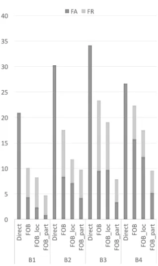
The error in coveringR with a P-rect depends on the shape of R, the number of subregions and the distance bounds. We consider the following cases for four policy regions shown in Figure 5.
- Direct approach:Ris completely covered by the P-rect formed by rings centered atV0andV1 and being the narrowest rings that contain all locations ofR. The
resulting P-rect is the smallest P-rectangle coveringRcompletely (Fig. 6a).
- Basic F indOptimalBoundsalgorithm (F OB): Fig 6b shows the implementa-tion of basic error optimizaimplementa-tion algorithm presented in Secimplementa-tion 5.
- F indOptimalBoundswith adjusted verifiers’ location (F OBloc):We have
ad-justed the verifiers’ locations heuristically to observe the impact on accuracy.
- F indOptimalBounds algorithm with partitioned regions (F OBpart): We
(a) (b) (c) (d)
Fig. 5.Policy regions (from left to right): Building B1, B2, B3, B4 in binary image. We considered both regular shaped (B1) and relatively irregularly shaped regions (B2, B3, B4) to provide diversity to the experiment
(a) (b) (c) (d)
Fig. 6. (a) B4 is covered using direct approach, each ring touches two sides of the region (b) FOB approach: to reduce total error, a small amount of false rejection area is introduced (c, d) Partitiong B4 into two separate regions and applying FOB on each.
in a binary matrix. Measurements, including locations, distance, area and errors are all in pixels.
Error and coverage comparison. Table 1 compares four approaches when applied to B1, B2, B3, B4.Notice that comparatively “regular” shaped policy regions (e.g., B1 in Fig. 5a,) can be covered more accurately than other regions; if we compare the best found errors, B1 has (FA, FR) error only (0.81,3.89)% against (4.16,5.58)% (B2), (3.34,4.53)% (B3) and (5.16,4.4)% (B4).F OBpart
algorithm reduces this irregularity to some extent reduces the total error ofF OB by 7.82(B2),15.48(B3) and 12.78%(B4). Our algorithm trades much better than naively covering a region (the direct approach), F OB reduces total error from direct approaches by 10.84(B1),12.68(B2),10.78(B3) and 4.31%(B4).
Comparison to existing approaches. Computing optimal bounds for veri-fiers so that the two types of errors are optimized - is only attempted once in existing literature on in-region verification and localization methods, by Sastry
et al.[16].They have placed 5 verifiers inside a 100m by 100m room. They were able to achieve a coverage (True Acceptance) of 93% with 7% total error.We compare by considering a policy region of 100×100 resolution in the universe of 640×640 pixels. Each pixel represents 1m, so we replicate the scenario of cov-ering a 100m by 100m room. Using two verifiers, we achieved a 96.4% coverage (TA) and 4.1% total error. Figure 7 illustrates the two approaches.
(a) (b)
Fig. 7.(a) Sastryet. al.[16]: 5 nodes manually placed inside the region to provide a coverage (TA) of 93% (b)FindOptimalBounds: 2 nodes manually placed outside the region to provide a coverage (TA) of 96.4%. It also reduces total error from 7% to 4.1%.
1 2 3 4 5
0 5 10 15 20
F AWeight
Error
(%)
F A F R
Fig. 8. False acceptance weight VS error. Increasing FA weight results in lesser FA error, and higher FR error. Service providers can select a weight that suits their security goal the most.
can be adjusted to capture requirements of different applications. We give the concept of weighted error metric:EΠ,Rw=WF A×F AΠ,R+WF R×F RΠ,R.The
increased weight for FA reduces FA error. For this analysis, we considered pol-icy region B2 (fig. 5b) andF OBLoc approach, and found that for FA weights
{1,2,3,4,5}, the resulting FA errors are{7.09,3.14,1.43,0.95,0.75}%. Figure 8 shows the results. For this analysis we considered policy regionB2 (fig. 5b) and F OBLoc approach.
7
Related Work
DirectF OB F OBLocF OBpart
B1
TA 100 94.2 94.1 96.1 FA 20.94 4.31 2.32 0.81
FR 0 5.79 5.89 3.89
E 20.94 10.1 8.22 4.71
B2
TA 100 90.77 95.3 94.41 FA 30.24 8.33 7.09 4.16
FR 0 9.22 4.69 5.58
E 30.24 17.56 11.78 9.74
B3
TA 100 77.63 90.61 95.47 FA 34.13 9.5 9.69 3.34
FR 0 13.84 9.38 4.53
E 34.13 23.35 19.08 7.87
B4
TA 100 93.35 94.7 95.6 FA 26.65 15.7 12.21 5.16
FR 0 6.64 5.3 4.4
E 26.65 22.34 21.07 9.56
Table 1.Four coverage approaches are applied to B1, B2, B3, B4. E = FA + FR is total error. Best found FA, FR and E range from 0.81 to 5.16%, 3.89 to 5.58% and 4.71 to 9.74%. Best found total cov-erage ranges from 94.41 to 96.1%
Fig. 9.FA, FR Error Comparison among different approaches when applied to B1, B2, B3, B4. The regularly shaped region B1 has the lowest FA and FR errors com-pared to other relatively irregular shaped regions, in all four approaches.
provably secure authentication for users inside R together with quantifiable error, for arbitrary region, is novel and not shared by any existing work. The system in [22] provides location verification for a region without using a secret key and without requiring user authentication.
Secure positioning in multiple verifier settings is considered in [6], who proved that security against multiple adversaries (adversaries at multiple locations) is only achievable in the bounded retrieval model. [26] use bounded retrieval model, and like us, they also take advantage of directional antennas to provide in-region security. However, they cannot provide security against adversaries that reside inside the region.
Numerous distance upper bounding protocols have been proposed to date [4, 3, 21, 9]. However the only distance lower bounding protocol with provable security against three main kind of attacks is [27]. inRA uses the formal model and protocol constructions of [21] and [27] for its DUB and DLB components.
8
Concluding Remarks
We motivated and defined the problem of in-region authentication, and defined correctness and security of inRA protocols for a region R. We proposed an approach to constructing secure inRA protocols that uses distance bounding protocols to coverR with a P-rect, and gave an efficient algorithm to optimize the P-rect by minimizing the total error. We also proposed a basic two-verifier protocol with provable properties. Our approach provides flexibility to define er-ror functions that are suitable for particular applications, and increase accuracy by choosing more verifiers.
We showed error performance of our optimization algorithm on different shaped policy region and verified improved accuracy when the region is sub-divided into two. Optimizing error under real life constraints on the location of verifiers, the number of verifiers, particular error function, and optimization in three dimensional spaces are challenging directions for future research.
References
1. Ahmadi, A., Safavi-Naini, R.: Distance-bounding identifiaction. In: 3rd Interna-tional Conference on Information Systems Security and Privacy (2017)
2. Bae, S.E.: Sequential and parallel algorithms for the generalized maximum subar-ray problem. Ph.D. thesis, University of Canterbury (2007)
3. Boureanu, I., Mitrokotsa, A., Vaudenay, S.: Secure and lightweight distance-bounding. In: Lightweight Cryptography for Security and Privacy, pp. 97–113. Springer (2013)
4. Brands, S., Chaum, D.: Distance-bounding protocols. In: Advances in Cryptology - EUROCRYPT’93. pp. 344–359. Springer (1993)
5. ˇCapkun, S., Hubaux, J.P.: Secure positioning of wireless devices with application to sensor networks. In: Proceedings of the 24th Annual Joint Conference of the IEEE Computer and Communications Societies. vol. 3, pp. 1917–1928. IEEE (Mar 2005)
6. Chandran, N., Goyal, V., Moriarty, R., Ostrovsky, R.: Position based cryptography. In: Advances in Cryptology-CRYPTO 2009, pp. 391–407. Springer (2009) 7. Chiang, J.T., Haas, J.J., Hu, Y.: Secure and precise location verification using
distance bounding and simultaneous multilateration. In: Proceedings of the 2nd ACM conference on Wireless Network Security (WiSec ’09). pp. 181–192. New York, NY, USA (2009)
8. Desmedt, Y.: Major security problems with the unforgeable(feige)-fiat-shamir proofs of identity and how to overcome them. In: Proceedings of SECURICOM. vol. 88, pp. 15–17 (1988)
10. Fan, T.H., Lee, S., Lu, H.I., Tsou, T.S., Wang, T.C., Yao, A.: An optimal algo-rithm for maximum-sum segment and its application in bioinformatics. In: Interna-tional Conference on Implementation and Application of Automata. pp. 251–257. Springer (2003)
11. Francillon, A., Danev, B., ˇCapkun, S.: Relay attacks on passive keyless entry and start systems in modern cars. In: NDSS (2011)
12. Grenander, U.: Pattern Analysis, Applied Mathematical Sciences, vol. 24. Springer New York, New York, NY (1978). https://doi.org/10.1007/978-1-4684-9354-2 13. Hammad, A., Faith, P.: Location based authentication (Aug 1 2017), uS Patent
9,721,250
14. Metz, C.E.: Basic principles of roc analysis. In: Seminars in Nuclear Medicine. vol. 8, pp. 283–298. Elsevier (1978)
15. Rasmussen, K.B., Castelluccia, C., Heydt-Benjamin, T.S., ˇCapkun, S.: Proximity-based access control for implantable medical devices. In: Proceedings of the 16th ACM Conference on Computer and Communications Security (CCS’09). pp. 410– 419. Chicago, Illinois, USA (Nov 2009)
16. Sastry, N., Shankar, U., Wagner, D.: Secure verification of location claims. In: Proceedings of the 2nd ACM Workshop on Wireless Security. pp. 1–10. New York, NY, USA (2003)
17. Schwartz, J.: Bing maps tile system. https://msdn.microsoft.com/en-us/library/bb259689.aspx, accessed: 2016-04-13
18. Singelee, D., Preneel, B.: Location verification using secure distance bounding pro-tocols. In: IEEE International Conference on Mobile Adhoc and Sensor Systems Conference, 2005. pp. 7–pp. IEEE (2005)
19. Takaoka, T.: Efficient algorithms for the maximum subarray problem by distance matrix multiplication. Electronic Notes in Theoretical Computer Science61, 191– 200 (2002)
20. Takaoka, T., Pope, N.K., Voges, K.E.: Algorithms for data mining. In: Business Applications and Computational Intelligence, pp. 291–315. Igi Global (2006) 21. Vaudenay, S., Boureanu, I., Mitrokotsa, A., et al.: Practical & provably secure
distance-bounding. In: Proceedings of the 16th Information Security Conference (2013)
22. Vora, A., Nesterenko, M.: Secure location verification using radio broadcast. De-pendable and Secure Computing, IEEE Transactions on3(4), 377–385 (2006) 23. Warner, J.S., Johnston, R.G.: A simple demonstration that the global positioning
system (gps) is vulnerable to spoofing. Journal of Security Administration25(2), 19–27 (2002)
24. Weddell, S., Langford, B.: Hardware implementation of the maximum subarray al-gorithm for centroid estimation. In: Proc. of Twenty-first Image and Vision Com-puting Conference New Zealand (IVCNZ 2006). pp. 511–515 (2006)
25. Wei, Y., Guan, Y.: Lightweight location verification algorithms for wireless sensor networks. IEEE Transactions on Parallel and Distributed Systems24(5), 938–950 (2013)
26. Yang, R., Xu, Q., Au, M.H., Yu, Z., Wang, H., Zhou, L.: Position based cryptogra-phy with location privacy: A step for fog computing. Future Generation Computer Systems (2017)
27. Zheng, X., Safavi-Naini, R., Ahmadi, H.: Distance lower bounding. In: Information and Communications Security, pp. 89–104. Springer (2014)
A
Explanation on the Erasure Sequence
The security of DLB protocol presented in [27] stands on the assumption that the prover devices are memory restricted in a way that they are not able to store malicious codes in the memory - as malicious codes potentially allow the device to delay their response to verifier’s challenge. Erasure sequence solves this problem, which is a random binary sequence - sent by the verifier in each round of fast exchange phase, just after the challenge. Size of the erasure sequence is determined so that all the memory of the prover device, barring the part required by prover to execute the protocol (code to execute the protocol, responses that are going to be used in the future), is replaced by the sequence. Prover must prove to the verifier that it has actually stored the whole erasure sequence, and this is done by making the prover send aproof of erasureback to the verifier in each round, just after the response bit. The generation of proof of erasure is as: prover reads the erasure sequence in reverse order, then applies a cryptographic hash function on it. This design forces the prover in storing the complete erasure sequence before sending the proof to the verifier.
B
Security models of
Π
rectDU Band
Π
rectDLBSecurity model of ΠDU B
rect presented in [21]
Definition 5. (DF-resistance ofΠDU B
rect )ΠrectDU B isαU-resistant to DF attack if
(∀s)(∀P∗) (∀locV)such that d(locV, locP∗)> BU)(∀rk) we have,
P rrV
OutV = 1 :
x←Gen(1s, r k)
P∗(x)↔V(x;rV)
≤αU. (13)
HereP∗ is any dishonest prover and in a concurrent setting, a polynomially bounded number of honestP(x0) andV(x0) close toV(x), with independentx0, are allowed.
Definition 6. (MiM-Resistance of ΠrectDU B) ΠrectDU B is βU-resistant to MiM
at-tack if (∀s) (∀m, l, z) that are polynomially bounded, (∀A1, A2) polynomially
bounded, for all locations such thatd(locPj, locV)> BU, wherej∈ {m+ 1, ..., l},
we have
P rrV
OutV = 1 :
(x)←Gen(1s, r k)
P1(x), ..., Pm(x)↔ A1↔V1(x), ..., Vz(x)
Pm+1(x), ..., Pl(x)↔ A2(V iewA1)↔V(x)
≤βU. (14)
Here, the attacker is represented by (A1,A2), and the probability is over all
The attacker can have a learning phaseA1during which it interacts withm
honest provers and z verifiers. It then uses the view ofA1 in the attack phase,
and engages asA2 in l−mprotocol instances between honest provers and the
target verifier.
Definition 7. (CF-Resistance of ΠDU B
rect ) ΠrectDU B is(γU, ηU)-resistant to
collu-sion fraud if(∀s) (∀P∗) (∀locV0)such thatd(locV0, locP∗)> BU,∀A
CFppt.if we
have,
P rrV
OutV0 = 1 :
(x)←Gen(1s)
P(∗)(x)↔ ACF ↔V 0(x)
≥γU, (15)
then there exists an extended6MiM attack withm, l, z, A1, A2, Pi, Pj, Vithat uses
interaction withP andP∗ both, and V in the learning phase, such that,
P rrV
OutV = 1 :
(x)←Gen(1s)
P1(∗)(x), ..., Pm(∗)(x)↔ A1↔V1(x), ..., Vz(x)
Pm+1(x), ..., Pl(x)↔ A2(V iewA1)↔V(x)
≥ηU. (16)
HereP(∗) is a prover that is either P or P∗. We have d(loc
Pj, locV)> BU,
for all j ∈ {m+ 1, l}. We implicitly allow a polynomially bounded number of P(x0), P∗(x0), and V(x0) with independent (x0), anywhere but no honest partic-ipant is close toV0.
Security model of ΠrectDLB presented in [27]
Definition 8. (DF-resistance of ΠDLB
rect )ΠrectDLB isαU-resistant to DF attack if
(∀s)(∀P∗) (∀locV)such that d(locV, locP∗)< BL)(∀rk), we have,
P rrV
OutV = 1 :
x←Gen(1s, r k)
P∗(x)↔V(x;r V)
≤αL. (17)
HereP∗ is any dishonest prover and in a concurrent setting, a polynomially bounded number of honestP(x0) andV(x0) far away fromV(x), with indepen-dentx0, are allowed.
Definition 9. (MiM-Resistance ofΠrectDLB)ΠrectDLB isβL-resistant to MiM attack
if(∀s)(∀m, l, z)that are polynomially bounded,(∀A1,A2)polynomially bounded,
for all locations such thatd(locPj, locV)< BL, wherej∈ {m+ 1, ..., l}, we have
P rrV
OutV = 1 :
(x)←Gen(1s, r k)
P1(x), ..., Pm(x)↔ A1↔V1(x), ..., Vz(x)
Pm+1(x), ..., Pl(x)↔ A2(V iewA1)↔V(x)
≤βL (18)
6
Here, the attacker is represented by (A1,A2), and the probability is over all
random coins of the protocol. V iewA1 is the final view of A1. This definition allows polynomially bounded number ofP(x0), P∗(x0), andV(x0) with indepen-dentx0, anywhere.
The attacker can have a learning phaseA1during which it interacts withm
honest provers and z verifiers. It then uses the view ofA1 in the attack phase,
and engages asA2 in l−mprotocol instances between honest provers and the
target verifier.
Definition 10. (CF-Resistance ofΠDLB
rect )ΠrectDLB is(γL, ηL)-resistant to
collu-sion fraud if(∀s) (∀P∗) (∀locV0 such thatd(locV0, d(locV0, locP∗)< BL) (∀A
CF
ppt.)such that
P rrV
OutV0= 1 :
(x)←Gen(1s)
P(∗)(x)↔ ACF ↔V 0(x)
≥γL, (19)
then there exists an extended MiM attack with m, l, z, A1, A2, Pi, Pj, Vi that uses
interaction withP andP∗ both, and V in the learning phase, such that,
P rrV
OutV = 1 :
(x)←Gen(1s)
P1(∗)(x), ..., Pm(∗)(x)↔ A1↔V1(x), ..., Vz(x)
Pm+1(x), ..., Pl(x)↔ A2(V iewA1)↔Vx
≥ηL. (20)
HereP(∗) is a prover that is eitherP or P∗. We have d(loc
Pj,locV)< BL,
for all j ∈ {m+ 1, l}. We implicitly allow a polynomially bounded number of P(x0), P∗(x0), and V(x0) with independent (x0), anywhere but no honest partic-ipant is far away fromV0.
C
Proofs
Theorem 1.
Proof (inF Security). We prove that if there is an inF adversary against the inRA protocol, then either there is a DF adversary against the DUB protocol, or there is a DF adversary against the DLB protocol. More specifically-If there exists a PPT malicious proverP∗ such thatloc
P∗∈ R/ , and has an inF
success probabilityα0 > αin inRA protocolΠR, then
1. we can construct a PPT malicious proverP∗
u such thatd(locV, locP∗
u)> BU,
and has a DF success probabilityα0u> αu in DUB protocolΠrectDU B; or
2. we can construct a PPT malicious proverP`∗such thatd(locV, locP∗
u)< BL,
Fig. 10.inF security ofΠrect - Proof by reduction.
To prove 1, we assume that there exists a malicious inF proverP∗ against the inRA protocol, andd(locV, locP∗)> BL.
The malicious proverPu∗(that is outside the upper boundBU) must convince
a challengerC(that acts as the verifier ofPu∗in aΠrectDU B protocol instance), that it is inside the distance upper boundBU fromC. In order to do this,Pu∗interacts
withP∗ and acts as a challenger ofP∗ (i.e., acts as both verifiersV0, V1forP∗
in aΠrect protocol instance). In other words,P∗ is used as a subroutine ofPu∗.
Figure 10 shows the setup and the interactions amongC,P∗
u andP∗.
The challengerCsets the system and sends toPu∗, the security parameter 1s
and the secret keyx←Gen(1s, r V).
During the initialization phase ofΠDU B
rect withC,Pu∗ does the following:
1. Setxu
1 =x. This is the secret key shared with the verifierV0in distance upper
bounding. The other secret keys required by P∗ are selected randomly by Pu∗:xu
2, xl1, xl2∈ {0,1}`,`is the length of secret keyx.
2. Sends security parameter 1s, secret keysxui, xli (fori={1,2}) toP∗ which acts as a subroutine.
3. Receives Nu pi, N
`
pi generated byP
∗ as a part of its own initialization phase
ofΠrect; each of these is ak-bit binary string.
4. Discards all butNpu1 and sends it toC. 5. Receives Nu
6. SetsNu V0 =N
u V, M
u
1 =Mu, and Randomly selects binary stringsNVu1, N
l V0, Nl
V1, each of lengthk, andM
u
2, M1l, M2l, each of length 2n, respectively, and
sends all these strings toP∗.
In the fast-exchange phase ofΠrectDU B,Pu∗ does the following
-1. In each of thenrounds of the fast exchange phaseΠrectDU B, receives challenge
bitcτ,1≤τ≤nfromC, setscu1τ =cτ.c
u
2τ is set randomly. It sendsc
u 1τ, c
u 2τ
toP∗. Upon receiving the response bit ru 1τ, r
u
2τ from P
∗, sends ru
1τ back to C, discardsru
2τ.
2. In order to simulate the challenges of DLB instance for P∗, Pu∗ does the following:
runs for anothernrounds with the delay between any two challenges chosen the same as that of a DLB instanceΠrectDLB. It randomly generates two
chal-lenge bitscl1τ, c
l
2τ, and two binary strings RS1, RS2, in each round (RSi is
the erasure sequence for DLB corresponding to verifierVi); it sendscl1τ, c
l 2τ
toP∗ immediately followed byRS
1, RS2; and receivesrliτ, hiτ, (i={1,2})
and discards all.
Now, the steps given above clearly takes polynomial time to execute. There-fore, sinceP∗takes polynomial time (as assumed),Pu∗’s running time is polyno-mial as well.
Pu∗ is indistinguishable from a real challenger for P∗ as it (Pu∗) forwards all the messages of its challenger C to P∗, and the rest of the messages (required forV0’s DLB instances inP∗ andV1’s DUB and DLB instances) are randomly
chosen with the same length and completely indistinguishable from the original messages.
The response tableau
1 generated byP∗is the only meaningful response table
here. The other tables al
1, au2, al2 do not affect P∗ in generating the correct
re-sponse for V0’s DUB instance in time, as response tables are independent from
each other and from other verifiers.
As per assumptions, P∗ has a inF success probability of α0 > α in inRA, which in this case, is only the success probability of its DUB instance with verifier V0. According to inF definition [Def 2], it follows that all the responsesru1τ from
P∗ must be correct and reach verifier in time. Therefore, all the responses rτ
from Pu∗ must be correct as well, and reach the verifier (challenger C) in time. It implies that according to DUB DF definition [Def 5], Pu∗ has a DF success probability of α0u> αu in DUB.
For the proof of 2, we construct the PPT malicious proverP`∗ using a similar method.
Proof (inMiM Security).
We show that, if there exists a PPT adversaryAwho has an inMiM success probability β0 > β in inRA protocolΠrect, then
1. either we can construct a PPT adversaryAu who has a MiM success
Fig. 11.inMiM security ofΠrect- Proof by reduction: Learning Phase
2. we can construct a PPT adversary A` who has a MiM success probability
β`0 > β` in DLB protocolΠrectDLB.
To prove 1, assume there is an adversary Aas above, and suppose it cannot be used to constructA`.
The adversaryAu, who does not have a key but is inside the distance bound
BU from a challengerCand interacts with multiple honest provers, aims to make
C (that acts as a verifier for Au ) output accept in a ΠrectDU B protocol instance.
The adversary has access toAas described above, In order to achieve its goal,Au
interacts withAand acts as a challenger ofA(i.e., acts as both verifiersV0, V1
forAin aΠrect protocol instance). In other words,Ais used as a subroutine of
Au. Figure 11 and 12 shows the setup and the interactions amongC,AuandA.
The challengerCsets up the system and provides the security parameter 1s
toAu.
In the learning stage ofΠrectDU B,Au does the
following-1. Sends security parameter 1stoA.
2. Receives the set ofmproversP ={P1, ..., Pm}and the list ofzset of verifiers
V={V1, ...,Vz} fromA. We assume that each verifier setVi∈Vconsists of
a pair of verifiers. 3. SendsP,Vto challenger.
4. Receives messagemu
ij sent by proverPi to VerifierVj Also, receives message
mu
jisent by verifierVj to proverPi.
5. Randomly selects stringsmlijandmlji. Sends all these messages (muij,muji,mlij andmlji) toA.
6. Receives tampered message muij0, mlij0 from A originally sent by prover Pi
to verifier Vj. Also, receives tampered message mu
0
ji, ml
0
ji from A originally
sent by verifierVj to proverPi. Discardsml
0
ji, m l0
ij and sends the remaining
messages to the challenger (to corresponding verifiers and provers). In the initialization phase of the attack stage inΠDU B
rect ,Adoes the following.
In the following,i, j are used to index the verifier and the prover, respectively. 1. Sends security parameter 1stoA.
2. Receives a set of θ proversP ={P1, ..., Pθ} (a different set of provers from
the learning phase) fromA. 3. ReceivesNu
Pj,i, N
`
Pj,i, (m+ 1≤i≤`) fromA, each of these is ak-bit binary
string.Nu
Pj,i is the DUB nonce that is generated by the prover Pj, and is
intended to reach the verifiersVi,i={1,2},j ={1, .., θ}.
4. SetsNPj =N
u
Pj,1 and sends to challengerC. Discards the rest of the nonces. 5. ReceivesNVj, MVj of lengthkand 2nrespectively, from the challenger; these
are intended to reach proverPj.
6. SetsNu
Vj,1 =NVj andM
u
Vj,1 =MVj. Randomly selects binary stringsN
u Vj,2, N`
Vj,i of lengthkandM
u Vj,2, M
`
Vj,i of length 2nrespectively and sends all of
In the fast-exchange phase of attack stage inΠDU B
rect ,Au does the following
-1. For each round τ, τ = {1, ..., n} of the fast exchange phase of ΠrectDU B for proverPj (1≤j≤θ),Au receives a challenge bitcτj fromC.
2. Setscuτj,1 =cτj, picksc
u
τj,2 randomly. Sends both challenge bits toA. 3. Receives responsesruτj,ifromA. Setsrτj =r
u
τj,1and sends back toC. Discards rτuj,2.
4. In order to simulate the challenges of theΠDLB
rect instance forA,Audoes the
following:
runs for anothern rounds (rounds indexed withω) with the delay between the two challenges chosen to be the same as that of aΠDLB
rect instance;
ran-domly generates challenge bitsc`
ωj,iand a binary stringRSωj,iin each round
(RSωj,i is the erasure sequence); sendsc
`
ωj,i to the A, immediately followed
byRSωj,i; receives responsesr
`
ωj,i, hωj,i fromA, and discards both.
Now, the steps given above clearly take polynomial time to execute, there-fore, because A takes polynomial time (as assumed),Au’s running time is also
polynomial.
Au is indistinguishable from a real challenger for A as Au forwards all the
messages of its challenger C to A, and the rest of the messages (required for V0’sΠrectDLB instances inAuandV1’sΠrectDU B andΠ
DLB
rect instances) are randomly
chosen with the same length and completely indistinguishable from the original messages.
The response tableau1 generated byAis the only meaningful response table
here. The other tables al1, au2, al2 do not affectAin generating correct response
for V0’s ΠrectDU B instance in time, as response tables are independent from each
other and from other verifiers.
As per the assumptions, A has a inMiM success probability of α0 > α in inRA, which in this case, is the success probability of only its ΠDU B
rect instance
with verifierV0. According to inRA inMiM definition [Def 3], it follows that all
the responsesru
1τ fromA must be correct and reach verifier in time. Therefore,
all the responses rτj from Au must be correct as well, and reach the verifier
(challenger C) in time. It implies that according to ΠDU B
rect MiM definition [Def
6],Au has a MiM success probability ofβu0 > β in ΠrectDU B.
For the proof of 2, we construct the PPT adversaryA`using a similar method.
Proof (inCF Security).Lets assume that as per the inCF resistance definition of inRA (Definition 4), we have an experimentexpinCF =P∗(x)←→ AinCF ←→
V0(X), whereP∗ is a malicious prover who is outside the region R. Ifc1, ..., cn
are some random challenges from one of the verifiersV, let us defineV iewi to
be the view ofACF before receivingc
ifromV. We also define a random variable
Wi, whereWi=wi is all the informationACF receives fromP∗. It is important
to note thatwi must be received before it is too late to send the responseri to
V. This wi is exploited in the later experiment, where the adversary (A1,A2)
will run a MiM attack.
As assumed, for each verifier Vi ∈ V, the response tables au of the DUB
protocolΠDU B
![Fig. 1. Location verification for (a) circular regiondoes not give perfect coverage, and (c) arbitrary shaped regionare placed inside Rthat is perfectly covered by asingle verifier placed at the center of R, (b) arbitrary shaped region R, a single verifier R, multiple verifiers R ([16]’s approach), also does not give perfect coverage.](https://thumb-us.123doks.com/thumbv2/123dok_us/7983345.1324361/3.612.153.460.112.216/location-verication-regiondoes-regionare-verier-arbitrary-verier-veriers.webp)

![Fig. 7. (a) Sastryregion to provide a coverage (TA) of 96 et. al. [16]: 5 nodes manually placed inside the region to provide acoverage (TA) of 93% (b) FindOptimalBounds: 2 nodes manually placed outside the.4%](https://thumb-us.123doks.com/thumbv2/123dok_us/7983345.1324361/19.612.214.404.288.442/sastryregion-provide-coverage-manually-acoverage-findoptimalbounds-manually-outside.webp)