R E S E A R C H
Open Access
Decentralized practical design and centralized
benchmark for analog network coding
Enoch Lu
*, Zihao You and I-Tai Lu
Abstract
This article proposes both centralized and decentralized design schemes for an analog network coding multiple-input multiple-output system with a relay node between two end nodes. The proposed centralized scheme is called the generalized iterative approach (GIA). It jointly designs the precoders and decoders at the two end nodes, and the processor at the relay to maximize the sum mutual information. Numerical results for the per-node power constraint show the convergence behavior of the GIA and give a performance benchmark for the analog network coding scheme. The proposed decentralized scheme is a practical joint transceiver and signaling design scheme. The keys to its low signaling load are time-division duplex and a symmetric relay processing matrix. The proposed signaling protocol enables the needed information, including channel state information (CSI), to be available at each node. With the needed CSI, a novel symmetric processor design at the relay is developed to maximize an approximate sum mutual information formula (to reduce the signaling loading, the precoders at both end nodes and the noise propagated from the relay are not considered). Employing singular value decomposition transceivers at the two end nodes, it is remarkable that the proposed decentralized approach performs almost as well as the centralized GIA design. It is concluded that the proposed decentralized scheme is a feasible way to implement analog network coding systems.
Keywords:Amplify-and-forward, Analog network coding, Mutual information, MIMO, Precoder, Signaling, TDD, Transceiver design, Two-way relaying
1. Introduction
Analog network coding (e.g., [1-16]), also known as two-way amplify-and-forward relaying, is a bi-directional re-laying technique. Its data transmission takes half the time of conventional bi-directional relaying. Moreover, it accomplishes this feat with simpler relay processing than another network coding technique, decode-and-forward network coding [1]. In analog network coding, both end nodes transmit simultaneously to the relay. The relay then processes its received signal and transmits it back to the end nodes. Finally, the end nodes then subtract their self-interference and decode their desired data.
There is no restriction on how many antennas each node needs to have in order for the system to do analog network coding. There are works on all single-antenna nodes (e.g., [2-4]). There are also works where the nodes can have multiple antennas (e.g., [5-16]). The multiple
antennas can aid in multiplexing and/or diversity. Con-sequently, the rest of this article is about the case when each node has multiple antennas.
When each node has multiple antennas, one obvious and flexible approach is to use input multiple-output (MIMO) linear processing: a precoding and decod-ing matrix at each end node and a processdecod-ing matrix at the relay. However, the design of these five matrices is not triv-ial. Some papers try to optimize according to some criteria (e.g., [8-11]) while others seek to propose low-complexity heuristics (e.g., [12,13]). Since the optimization problems are highly nonlinear, the solutions have only been derived numerically (or approximately) and are innately sub-optimum. Moreover, they are not implementable unless they are supportable by practical signaling.
Some have realized this need to consider signaling. For example, Panah and Heath Jr [14] and Roemer and Haardt [15] have proposed channel estimation tech-niques to supplement their designs. However, both works assume that no channel state information (CSI) is * Correspondence:[email protected]
Department of ECE, Polytechnic Institute of NYU, 6 MetroTech Center, Brooklyn, NY 11201, USA
available at the relay. In [14], the relay basically just scales and forwards its received signal. In [15], the relay process-ing does not have to be just a scalprocess-ing. But, it is independ-ent of the currindepend-ent CSI. There may be some improvemindepend-ent if CSI-dependent relay processing can be enabled.
Therefore, this article proposes a joint,but decentralized, transceiver and signaling designawith the following goal: to have high-performing MIMO linear processing, not just scaling, at each node using only a small amount of signal-ing. The practical signaling protocol proposed uses time-division duplex (TDD) and enables the relay to estimate its two outgoing channels (i.e., the channels from the relay to the two end nodes). It also enables the two end nodes to estimate the two effective channels between themselves (i.e., the link from one end node through the relay to the other end node and the same link but in the opposite dir-ection). Most importantly, it enables the two end nodes to cancel their self-interference.
To help keep the amount of signaling low, the proposal has the relay design its own symmetric relay processing matrix. The symmetry and the use of TDD together cause the end-to-end channel in one direction to be the trans-pose of the other direction’s, i.e., reciprocity holds for the two effective channels between the two end nodes. (The conjugate-transpose instead of the transpose is used in a lot of literature for representing the channel reciprocity. However, the conjugate-transpose should be used only for time reversal transmissions. Discussions on reciprocity can be found in most electromagnetic textbooks (e.g., see [17,18])). An end node needs to know the effective channel in each direction in order to choose a channel-dependent precoder and decoder. In general, knowing one effective channel does not imply knowing the other thus necessitat-ing signalnecessitat-ing both of them. Due to the symmetry and TDD, only one effective channel needs to be signaled here.
Another design decision is to sequentially design the relay processor and the end node processors; the relay designs its processor and then the end nodes design their own. There are no iterations between the processors. The major benefit of this choice is avoiding signaling repeatedly between the nodes. The chosen way to enable this sequential design is to have the relay design its processor ignoring the precoders, decoders, and the noise propagated from the relay. Though there may be some degradation in the sum mutual information, this decoupling substantially reduces the complexity of the relay. In turn, the lower complexity admits a shorter hardware timeline, etc.—reducing the dur-ation of an analog network coding transmission. Two relay designs which comply with the above design choices are a heuristic approach RRANOMAX in [12] and a novel itera-tive scheme herein developed which seeks to maximize an approximation to the sum mutual information.
To evaluate the performance of the proposed decentralized scheme, a generalized iterative approach (GIA) is developed
for jointly designing the precoders, decoders, and relay processor to maximize the true sum mutual information. The GIA is a centralized scheme where all CSI, noise, and source statistics have to be known at a central processing unit and, in addition, the processed results have to be available at the end and relay nodes. Because of the large amount of signaling load, the GIA is not very practical but can be employed for generating a performance bench-mark. Although mutual information maximization for MIMO relay systems has been studied extensively, those for analog network coding systems have only been re-cently introduced in [6,7]. Both [6,7] are different from the GIA in that they are both based on the assumption that source precoders are given beforehand. Like the GIA, the studies [9,10] are also for the design of the precoders, de-coders, and relay processor. However, its criterion is mini-mum mean squared error (MMSE). To the best of the authors’ knowledge, our GIA is the first work on joint precoders, decoders, and relay processors design to maximize the sum mutual information of MIMO analog network coding systems. It is known that the MMSE and mutual information are related for a MIMO channel with Gaussian noise (Equation 22 in [19]). However, that rela-tion is not satisfied for analog network coding systems be-cause of the following two reasons. First, the relay and precoders chosen for the maximum sum mutual informa-tion case are different from those for the MMSE case. Sec-ond, the noises at the two end nodes (which include the propagation of the noise received at the relay) for the maximum sum mutual information case are also not the same as those for the MMSE case.
The convergence behaviors of the proposed symmetric relay design and the proposed GIA are studied. Their sum mutual information performances are also studied. It is shown numerically that the decentralized approach performs almost as well as the centralized benchmark, the GIA. It is thus concluded that the proposed decentralized approach is a feasible way to implement analog network coding.
The outline of this article is given as follows. Section 2 lays the formulation foundation. Section 3 presents the GIA, a novel centralized scheme for jointly design the precoders, decoders, and relay processor. Section 4 ex-plains the proposed signaling protocol for decentralized designs and gives a joint precoder–decoder design where no additional signaling is required. Following the decen-tralized signaling protocol, Section 5 proposes a novel de-sign for a symmetric relay processing matrix according to the approximate sum mutual information metric. The RRANOMAX design [12] is also summarized in Section 5. Numerical results are shown in Section 6. Conclusion is made in Section 7.
case).A’,A,A*,A–1,tr(A), |A|, ||A||F, and <A> stand for the transpose, conjugate, conjugate transpose, inverse, trace, determinant, Frobenius norm, and expectation of A, respectively.Irdenotes ther×ridentity matrix.0
de-notes the zero matrix with proper dimension.A> 0 de-notes thatAis a positive definite matrix. A⊗Bdenotes the Kronecker product of A and B. vec( ) and unvec( ) are the matrix vectorization operator and the inverse matrix vectorization operator, respectively. DIAG (σ1,σ2, . . .,σr) is a diagonal matrix where the elements {σ1,σ2,. . ., σr} are put on the main diagonal. {Ak} denotes the set of
matrices, A1, A2, etc. max(a,b) denotes the maximum of real numbers aand b. On the other hand, min (a,b) de-notes the minimum of real numbers a and b. (χ)+= max(χ, 0).
2. Analog network coding formulation
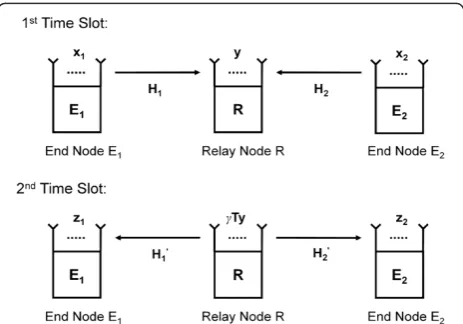
This article considers a TDD system with relay nodeR, equipped with MRantennas, between two end nodesE1 andE2, equipped withM1andM2antennas, respectively. Each node works in half-duplex mode, receiving and transmitting data in different time slots. These nodes perform analog network coding, completing a bi-directional communication between the two end nodes in just two time slots (see Figure 1)—note that this does not include the time slots for signaling. The problem will be formulated in the frequency domain. It is assumed that the guard time is larger than the delay spread so that there is no inter-symbol interference. It is also as-sumed that the duration for the system to complete a bi-directionary communication is much smaller than the coherence time so that the channels are considered sta-tionary within that duration.
Two time slots for data (not signaling) transmission are used in analog network coding. The end nodesE1andE2
broadcast signals x1=F1s1 and x2=F2s2, respectively, to the relay in the first time slot. The relay thus receives
y¼H1x1þH2x2þw: ð1Þ
The data vectorsiis adi× 1 vector and is precoded by
theMi×diprecoderFi; the scalardiis the number of data
streams fromEi. Each element ofsiis assumed to be
zero-mean and the entire vectorsisatisfies<sisi>¼σ2siI>0
. The MR×Mi matrix Hi (i= 1,2) is the Rayleigh fading
channel fromEito the relay,yis theMR× 1 relay received vector, and wis theMR× 1 Gaussian noise vector at the relay. The elements ofware zero mean and satisfy <ww* > =Φw>0. In this article, the transmit power of Ei is constrained by requiring
σ2
si trfFiFig ¼pi: ð2Þ
In the second time slot, the relay transmits γTy back to each end node. Here, T is its MR×MR processing matrix. The scalar γis chosen to ensure the relay power constraint
<ðγTyÞγTy>¼γ2
trð Þ ¼Q q;
withQ≡T Φwþ
X2
j¼1
σ2
sjHjFjFjHj !
T: ð3Þ
From (3), we observe that the power constraint on the relay processor depends on the precoders {Fi}. Due to
the channel reciprocity, Ei’s (i= 1,2) received signal vec-tor (of dimensionMi× 1) is
zi¼H 0
iγTHixiþH 0
iγTHjxjþH 0
iγTwþai ð4Þ
(j= 1 if i= 2 and j= 2 if i= 1). In the above, ai is the Mi× 1 Gaussian noise vector at Ei. It has elements with zero mean and satisfies<aiai >¼Φai>0. The vectors,
s1, s2, w, a1, and a2, are all independent of each other. Also, the channel matrix from the relay toEiis Hi'. For
convenience, letCij¼H0iγTHjdenote the effective chan-nel from the end nodeEj, through the relay, to the end nodeEi, and letni¼H
0
iγTwþai represent the effective
noise at the end node Ei, where i,j= 1,2. Equation (4) can thus be rewritten as
zi¼CiixiþCijxjþni; i≠j; i;j¼1;2; ð5Þ
where the effective noise covariance matrix is
Φni¼<nini >¼γ2H 0
iTΦwT∗HiþΦai: ð6Þ
Look at Ei’s (i= 1,2) received signal vector. It is clear that using only two time slots has causedxiandxjto be Figure 1Analog network coding schematic.For a TDD system,
mixed together inzi. That is,Eiinterferes with itself. Some-howthough,EiknowsCii, the effective channel from itself,
through the relay and back to itself. SinceEitransmittedxi, Ei knows xi as well and thus can subtract its
self-interference completely fromzi. Consequently, it obtains
^zi¼ziCiixi¼Cijxjþni; i≠j; i;j¼1;2: ð7Þ
To decodesj,Einow has the options of regular point to
point transmissions (e.g., applying adj×MidecoderGi).
3. Centralized design
Let Gi denote the decoder at Ei. Then, from [20], the
mutual information pertaining to the transmission of sj
fromEjtoEiis
Assuming all CSI, source and noise statistics are known at a centralized processing unit, we are to maximizeIE1+IE2by jointly designing the decoders {G1, G2}, precoders {F1, F2} and relay processor Tsubject to the per-node power constraints at the precoders (see (2)) and at the relay (see (3)).
Let {F1,F2,T} be known. Also let Gi;OPTΦniGi;OPT≠0
where
Gi;OPT¼ΠFjCijΦni1 ð9Þ
and where Π is any invertible square matrix. Note that the commonly used MMSE decoder and singular value decomposition (SVD) decoder (if FjCij is invertible) can also be expressed using (9). In this case, Corollary 1 of [20] shows thatGi,OPT is the optimum decoder and the mutual informationIEiin (8) becomes
IEi¼ log2
full column rank. Due to the wayT is made in this de-sign,γis not used. The scalarγis thus equal to 1.
The remaining task now is to choose the precoders {F1, F2} and relay processor T to maximize the sum mutual information, IE1+IE2, subject to the constraints (2–3). That is,
Obtaining an optimum solution to (11) is very difficult due to the intercoupling of the design variables, etc. Consequently, the GIA seeks to find a solution by de-coupling the choices for the precoders and relay proces-sor. It does this by iteratively designing them. Before looking at the GIA’s actual iterative procedure in Section 3.3, first look at Section 3.1 which gives a way to choose the precoders given the relay processorT. Then, look at Section 3.2 which gives a way to chooseTgiven the precoders. The reason is that the findings in Sections 3.1-3.2 are used in Section 3.3.
3.1. Fix relay processor and get precoders
Given a relay processorT, the cost function in (11), and the constraint (2), this section details one way to choose precoders {F1, F2}. As shown in (7), the two-way trans-mission can be considered as two independent single-user MIMO systems whenTis known. As there exists a closed-form solution for maximizing the mutual infor-mation of a single-user MIMO system subject to the per-node power constraint [20], the proposed way is to just apply that closed-form solution here: First, perform the eigenvalue decomposition.
while Ξj and Γj are diagonal matrices with the
eigen-values. As the eigenvalues are arranged in descending order,
Ξj¼DIAG ξj;1; ξj;2; . . .; ξj;rj
ð13Þ
has the rj largest eigenvalues and Γj has the remaining (Mj–rj) eigenvalues;rj= min(dj, rank(Cij)). Note thatVj
isMj×rjandUjisMj× (Mj–rj). Then, set
Fj¼ VjΦj 0MjðdjrjÞ
h i
; ð14Þ
whereΦjis a diagonal matrix with thelth diagonal entry
In (15),τis the number of positive φj,ll(see Lemma 2
in [20]) and,σ2sj andpjare defined in (2).
3.2. Fix precoders and get relay processor
Given precoders {F1,F2}, the cost function in (11), and the constraint in (3), this section details one way to choose relay processor T. The method of Lagrange multipliers can be used to set up the augmented cost function
ξð Þ ¼T IE1þIE2þλTðtrð Þ Q qÞ ð16Þ
where λT is an unknown Lagrange multiplier. In (16),
matrixTis what we are looking for in design whileλTis
solved for so that Tcan satisfy its corresponding power constraint. Setting the gradient of the augmented cost function in (16) with respect toTequal to zero, we obtain (see Appendix 1)
By using Kronecker products we obtain the relay pro-cessor from (17) for a givenλT:
timing an identity matrix. Thus, left multiplying (17) by T, taking the trace, and applying the power constraint in (3), we have
λT¼trðTZTX2TY2Þ=q: ð19Þ
Note that (18) givesTas a function ofTandλT.
More-over, (19) givesλTas a function ofT. Thus, one way to get
aTis to iterate between (18) and (19) until convergence.
3.3. The iterative procedure The GIA is as follows:
Step a. Setk= 0 and set the stopping thresholdδ> 0 and the maximum number of iterationskmax.
Randomly initialize the precoders and relay processor for the 0th iteration:F1,0,F2,0, andT0. Make sure they check the power constraints at the end nodes since the closed form solution (14) always guarantees that they are satisfied.
Else ifk=kmax, setFj=Fj,kandT=Tk+1and stop. Otherwise, setk=k+ 1 and return to step b.
After the above iteration is finished, remove any all zero columns from F1and F2. This does not changeIE1 and IE2in (10). However, it’s needed so that (8) can be simplified to (10). Also, scaleTto satisfy the relay power constraint if the iteration terminated before conver-gence. Let dpi;k¼ σ2sitr Fi;kFi;k
pi
. Observe that there is no need to checkdp1,kanddp2,kin step h due to
the proposed GIA. Extensive numerical studies have been performed and the convergent properties of the GIA are shown in Section 6.1. When the GIA converges, it will con-verge to a local extremum. It is difficult to prove whether the numerically derived solution is global optimum or not because the problem is highly nonlinear.
4. Decentralized design: protocol
As shown in (7),Ei(i= 1,2) needs to knowCiito remove
the self interference. Actually, each of the nodes needs certain information such as Cij, i≠j, in order to design
its processing matrix, decoder, etc. So, this section pro-poses a four-step protocol for the nodes to follow. To help explain why the protocol is constructed the way it is, perfect estimation for each channel sounding is as-sumed in this explanation.
The first step is for E1 and E2 to perform channel soundings so that the relay can estimateH1and H2. In the second step, the relay chooses a symmetric T—two possible ways are given in Section 5. Next, the relay picks γ so that (3) is satisfied. It can do this since it knows what precoders the end nodes will use (see step 4). In the third step, the relay performs two equivalent channel soundings, one precoded with γTH1 and the other precoded with γTH2. From these two soundings, Ei (i= 1,2) estimates the effective channel matrices Cii
and Cij (j≠i, j= 1,2). The first term is what Ei needs to
subtract its self-interference; Cii is exactly what is left
multiplying xi in (5). The second term is the effective
channel from Ej, through the relay, to itself. What is more, the transpose of the second term is the effective channel from itself to Ej—this is why the relay madeT symmetric.
In the fourth step, Ei (i= 1,2) designs its precoder Fi
and decoderGiwithout any signaling with the other end
node. How can they do this and still have F1 matchG2 and F2 match G1? Simple: E1 uses a reproducible algo-rithm based on its estimate ofC21to design its precoder F1. E2 follows the same algorithm with its estimate of C21so that it can knowE1’s precoderF1.E2can thus de-sign its decoderG2to matchE1’s precoderF1.E2andE1 proceed in an analogous fashion so thatE2’s precoderF2 and E1’s decoderG1match as well. Recall that the relay already picked γ in the second step since it knew what precoders the end nodes would choose. Thus, one add-itional requirement for this reproducible algorithm is that it must be unaffected by a positive scaling of C21. That is, the end node will result in the same precoder and decoder whether it is givenC21or ρC21 whereρ is any positive scalar. Though this last requirement may seem like a stringent restriction, the following example implementation of step 4 shows this is not necessarily the case. Moreover, the ability of the relay to calculate γ
before the end nodes design their precoders is very im-portant as explained in Appendix 2.
To illustrate step 4, here is an example forF1andG2. The effective channel C21 is fixed since the relay has already pickedTandγ. As in Section 3.1, letr1= min(d1, rank(C21)) be the number of data streamsE1will trans-mit. AtE1, it first takes an SVD ofC21
C21¼UΣV; ð20aÞ
where the singular values σ1, σ2, etc., are in descending order,U ¼½u1 . . . uMzandv¼v . . . vM1. Then,E1sets
F1¼α v1ejθ1 . . . vr1ejθr1
; ð20bÞ
where the phaseθl(l= 1,. . .,r1) is chosen such that the first non-zero element ofvlejθl is positive. And,α> 0 is chosen
to satisfy the power constraint. E2 also takes the same steps.E2takes a SVD ofC21
C21¼UeΣVe
; ð21aÞ
whereUe ¼½eu1 . . . euM2andVe¼½ev1 . . . evM1. For eachl= 1,. . .,r1, it choosesϕlsuch that the first non-zero
element ofevlejϕl is positive. Then, it chooses the scalar to
satisfy the power constraint.
vlejθl ¼evlejϕl; ∀l: ð21bÞ
Thus, E2 also gets F1. Equation (21b) depends on
σ1,. . .,σr1 being distinct, something that can be assumed for physical systems. Now,E2proceeds to set
G2¼ e
u
1ejϕ1 ⋮
e
ur1e jϕr1
2 4
3
5: ð22Þ
The end-to-end channel is thus
G2C21F1¼
σ1
⋱ σr1
2 4
3
5 ð23Þ
without any signaling between the two end nodes. More-over, E1 and E2 would have gotten the same precoder and decoder, respectively, if they had been usingρC21.
5. Decentralized design: relay processors
The decentralized protocol presented in Section 4 is very general and can support many possible relay processor designs as long as theirT’s are symmetric. Two possible designs are presented here as examples.
5.1. Iterative symmetric design (ISA)
discussed in Section 1. Furthermore, the noise propa-gated from the relay to the end nodes is ignored for con-venience. That is, this design considers a simplified version of mutual information:
cjð Þ ¼T Iþρ2CijCij; i;j¼1;2;i≠j: ð24Þ
Here,ρ2=pi/tr(Φai) signifies the transmit SNR (the
ra-tio between the total transmit signal power and the total receive thermal noise power) andcjis related to the mu-tual information of the effective channel Cij. The
prob-lem is
TOPT
f g ¼ arg max
T¼T0;trðTTÞ¼1ðc1ð Þ þT c2ð ÞTÞ ¼ arg max
T¼T0;trðTTÞ¼1c1ð Þ:T ð25Þ
The second“=”in (25) is due to
c1ð Þ ¼T c2ð Þ:T ð26Þ
Equation (26) itself follows from Cij¼C0ji which, in turn, is a result ofT=T'. The trace constraint is needed to keep the elements ofTfrom exploding to infinity. To search for such aT, the augmented cost function
ςð Þ ¼T c1ð Þ þT λtrðTTÞ ð27Þ
is introduced with the real Lagrange multiplierλ. Using the technique of variation, we obtain (see Appendix 3)
tr H2ΓaH 0
2TM1þλT
S
¼0 ð28Þ
for everyMR×MRsymmetric matrixS. In (28),
M1≜ρ2H1H1≥0; ð28aÞ
Γa≜j jΓΓ1 and Γ≜IþH 0
2TM1TH2>0: ð28bÞ
By Appendix 4, this in turn means thatH2ΓaH 0 2TM1þ
λTis skew-symmetric. That is,
2λT¼H2ΓaH 0
2TM1þ H2ΓaH 0 2TM1
0
: ð29Þ
Noting thatT ¼T, right multiply (29) byTand apply
the trace constraint in (25) to get λ. Since trNT¼
trnNT0o¼trTN0¼trN0T with N≜T2ΓaH 0 2TM1,
we have
λ¼ tr H2ΓaH 0 2TM1T
: ð30Þ
Finally, plugging (30) into (29), we have
T¼H2ΓaH 0
2TM1þ H2ΓaH 0 2TM1
0
2:tr H2ΓaH 0 2TM1T
: ð31Þ
Clearly, aTsatisfying (31) is a feasible solution to (25) as it is symmetric and satisfies the trace constraint of (25). As (31) gives an implicit expression ofTas a func-tion ofTitself, this naturally leads to the following itera-tive procedure to get T. Since (31) is a highly nonlinear equation ofT, averaging (step c) is used.
Step a Randomly initializeT0as anMR×MRsymmetric
matrix satisfying the trace constraint of (25). Setk= 0. Also, set the stopping thresholdδand the maximum number of iterationskmax.
Step b Use (28b) to calculateΓa,k(replacingΓabyΓa,k
andTbyTk.)
Step c SetTkþ1¼βTkþð1βÞT^kþ1where 0≤β< 1
andT^kþ1¼H2Γa;kH
0
2TkM1þ H2Γa;kH
0
2TkM1
ð Þ0
2:trH2Γa;kH
0
2TM1Tk
ð Þ . Note the similarity
betweenT^kþ1and (31).
Also, setdηkþ1¼ tr Tkþ1Tkþ1
1
.
Step d. Ifjc1ðTkþ1Þc1ð ÞTkj
c1ð ÞTk <δanddηk+ 1<δ, setT=Tk+1 and stop.
Else ifk = kmax, setT=Tk+1and stop. Otherwise, set
k=k+ 1 and go to step b.
As in the GIA approach, we transform the
optimization problem in (24) in the ISA approach into a root searching problem which attempts to solve for the relay processorTfor the system of nonlinear equations defined in (31). Thus, the convergence of ISA depends on the convergence of solving (31) iteratively using step c. As shown in [21], a proper selection of initial estimates will guarantee the convergence of the proposed ISA scheme. Extensive numerical studies have been performed and the convergent properties of the ISA are shown in Section6.1. When the ISA converges, it will converge to a local extremum. Recall that (24) is an approximate mutual information formula to enable our
decentralization. So, no optimality claim is made with regards to the actual sum mutual information.
5.2. RRANOMAX design
The second design is the relay processor design used in the RRANOMAX approach in [12]. It can be used when the relay noise covariance matrix is a scalar times an identity matrix, i.e., Φw=σ2I>0.. For completeness, we
K¼UKΣKVK: ð32Þ
DefineuK,1as the first column ofUk. Then, the initial
design of the relay processor is
Ω¼unvecuK;1: ð33Þ
TheMR×MRsymmetric matrix Ωcould be used asT but it is not. The reason is due to the nature/distribution of its singular values. So, instead, perform the SVD onΩ:
Ω¼UΩΣΩVΩ;withΣΩ ¼DIAG σΩ1;. . .;σΩMR
: ð34Þ
The singular values in (34) are arranged in descending order. The T will be obtained from Ω by replacing σΩ1;. . .;σΩMR byσ^T1;. . .;σ^TMR. That is,
T¼UTΣ^TVTwithΣ^T ¼DIAG ^σT1;^σT2;. . .;^σTMR
: ð35Þ
These new singular values are defined by
^ σTk ¼
ffiffiffiffiffiffiffiffiffiffiffiffiffiffiffiffiffiffiffiffiffiffiffi
μσ2
λk
þ
s
; k¼1;2;. . .;L
0 ; otherwise:
8 > < >
: ð35aÞ
Here,L= min{MR, min{M1,M2} + 1} andμis chosen so that^σT21þ^σ
T2
2þ⋯þσ^
T2MR¼1. In (35a),
λk¼ σ1;kþ1
σ2;kþ1
; ð36Þ
whereσi,kis thekth singular value ofHi(arranged in
de-scending order).
6. Numerical results
Without loss of generality, assume that the noise covari-ance matricesΦaiandΦware identity matrices. Also
as-sume that the source covariance matrices are also identity matrices (i.e., σ2
s1¼σ2s2¼1 ). The numbers of
antennas at the two end nodes are the same (i.e., M1= M2) and are equal to 4. The number of antennas at the relay node MR is either equal to M1 or 2M1. Consider uncorrelated Rayleigh fading channels where all channel matrices are normalized such that the Frobenius norm of Hj, j =1,2, is one. With the per-node power at each
end node asp1=p2=Pand the relay power asq =2P, we define “SNR” as 10 log10(P/M1). The reason is that it is the dB value of the ratio between the total transmit power (tr(FiFi*)) and the total thermal noise power (tr(Φai)) at an
end node. Here, the channels and the noise propagated from the relay are not included in the “SNR” definition. The stop parameters for the ISA, δ, and kmaxare chosen to be 0.001 and 50, respectively. The stop parameters for
the GIA, δ, and kmax are chosen to be 0.001 and 2000, respectively.
6.1. Convergence property of the GIA and ISA
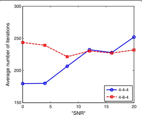
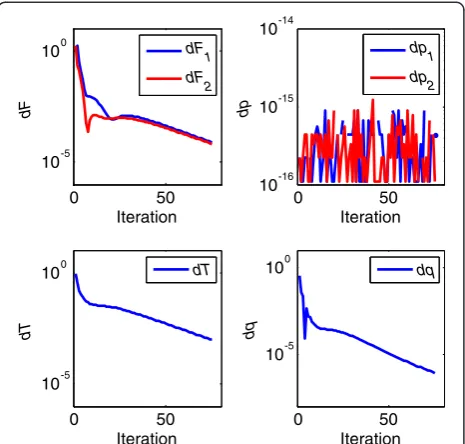
Figure 2 shows the average number of iterations the GIA needed per“SNR”for 100 channel realizations. One set of points is for the M1=M2=MR= 4 configuration while the other is for the M1=M2= 4 and MR= 8 one. There have been other iterative transceiver designs very similar to the GIA (e.g., [22]). For those designs, it was common to see the number of iterations increasing with the SNR. It is interesting that the phenomenon is not seen here for both antenna configurations. Figure 3 shows an example convergence plot for the GIA for theM1=M2= MR= 4 configuration and“SNR”= 0 dB. Observe thatdp1, kanddp2,kare very small as expected due to the use of the
closed-form solutions for the precoders.
Figure 4 shows the average number of iterations the ISA needed per “SNR” for 100 channel realizations. Again, the M1=M2=MR= 4 and, M1=M2= 4 and MR = 8 configurations are studied. It is very interesting that the trends for the two configurations are completely dif-ferent. The M1=M2= 4 and MR= 8 configuration sees a pretty constant average number of iterations needed over the different“SNR” values. On the other hand, the average number of iterations needed in the M1=M2= MR= 4 configuration decreases as the “SNR” increases. Consequently, in the M1=M2=MR= 4 configuration, there are many channel realizations for which the ISA converges almost right away. Figures 5 and 6 show ex-ample convergence plots for the ISA in both antenna configurations. For Figure 5 (the M1=M2=MR= 4 con-figuration), note that the number of iterations for“SNR” = 0 dB is very large compared to that for“SNR”= 20 dB.
0 5 10 15 20
150 200 250 300
"SNR"
Average number of iterations
4-4-4
4-8-4
Figure 2Average number of iterations the GIA needed per
For Figure 6 (theM1=M2= 4 andMR= 8 configuration), note that the number of iterations for “SNR”= 0 and 20 dB are basically the same. Both of these observations are consistent with our expectations after seeing Figure 4.
6.2. Sum mutual information performances
Recall that the decentralized signaling protocol proposed in Section 4 was flexible in terms of what relay processor Tthe relay used. So here, we demonstrate the sum mu-tual information performance of the proposed protocol
with three relay designs. The first one is to chooseT=I and is denoted as “Identity”. This is the simplest design. The second one is RRANOMAX where T is given in (36). The third one is using the ISA (see Section 5.1).
The protocol also allows for flexibility in the precoder and decoder design. For all three implementations of the protocol (one for each of the three relay processor de-signs), the SVD methodology described in (20a) to (22) is used for the precoder and decoder design. For reference, we also use (10) to evaluate the mutual information
0 50
10-5 100
dF
Iteration
0 50
10-16 10-15 10-14
dp
Iteration
0 50
10-5 100
dT
Iteration
0 50
10-5 100
dq
Iteration
dF1
dF2
dp
1
dp
2
dT dq
Figure 3Example convergence plot of the GIA forM1=M2=MR=
4 and“SNR”= 0 dB.
0 5 10 15 20
5 10 15 20 25 30 35 40
"SNR"
Average number of iterations
4-4-4 4-8-4
Figure 4Average number of iterations the ISA needed per
“SNR”.In the legends, 4-4-4 denotesM1=M2=MR= 4. Likewise, 4-8-4 denotesM1=M2= 4 and MR= 8.
0 5 10 15 20 25 30
10-4 10-2 100
d
Iteration
0 5 10 15 20 25 30
10-0.3 100.2
Iteration
Normalized c
1
(T)
"SNR"=0dB "SNR"=20dB "SNR"=0dB "SNR"=20dB
Figure 5Example convergence plot of the ISA forM1=M2=
MR= 4.To plot the curves for both“SNR”values in the same plot,c1 (T) is normalized for each“SNR”so that its value at the last iteration is unity.
d
0 10 20 30 40
100
Iteration
0 10 20 30 40
10-5 100 105
Iteration
Normalized c
1
(T)
"SNR"=0dB "SNR"=20dB "SNR"=0dB "SNR"=20dB
obtained using the proposed centralized GIA design. The GIA is described in Section 3.3.
Figures 7 and 8 show the sum mutual information,IE1 +IE2, for the three practical (decentralized) designs and the centralized GIA design. The antennas numbers de-pend on the figure. M1=M2= 4 for both figures.MR= 4 in Figure 7 andMR= 8 in Figure 8. Each of the curves is obtained by averaging the results of 100 channel realiza-tions. The number of data streams of each practical de-sign at each “SNR” for each channel realization is chosen so that it provides the maximum sum mutual in-formation. The number of data streams the GIA gives to
Ei (i= 1,2) is only determined in the last iteration; it is simply the number of non-zero columns ofFi.
From Figures 7 and 8, it is obvious that the “Identity” design of T has the worst performance and is greatly outperformed by the other three designs. The centralized
“GIA” design has the best performance. The imple-mentations of the proposed protocol with the “ISA”and
“RRANOMAX” relay processor designs come in second and third place, respectively. By comparing Figure 7 with Figure 8, it is easy to see that the performance gaps in-crease as the number of relay antennas inin-creases. In addition, the sum mutual information also becomes lar-ger as the number of relay antennas increases. Both of these observed phenomena are probably due to the in-creased freedom at the relay—the size of T increases from 4 × 4 to 8 × 8. Note that we normalize the Frobenius norms of all channel matrices to one.
Note that some kind of power loading at the precoders may increase the sum mutual information for the decentralized designs. However, performing the water filling procedure for power loading at the end nodes does not necessarily increase the mutual information. This is because the γ in (3) depends on the precoders.
When the power loading at the precoders changes the precoders {Fj} according to the water filling procedure,γ has to change too (becauseγdepends on {Fj}). But then, the optimized power loading done previously for a differ-ent γ is no longer optimum in the sense of maximizing the sum mutual information for the new γ. Moreover, water filling requires the noise covariance matrices Φni
in (6) to be available at end nodes. But,Φniis not
avail-able at the end node using the proposed decentralized protocol in Section 4. Thus, the water filling procedure is not applied here.
7. Conclusion
This article presents both practical and theoretical ad-vances for MIMO analog network coding, a technique which requires only two time slots (excluding the time slots required for signaling) to complete a bi-directional communication between two end nodes. For the prac-tical advance, the article proposes a decentralized joint transceiver and signaling design scheme which requires the system to work in a TDD mode and to have four channel soundings. With the proposed signaling scheme, each node gets the information needed for designing its own transmit and/or receive processors. The designs at all nodes are harmonized and coordinated such that no additional signaling overhead is needed. In particular, presented in this article is a novel iterative approach for designing a symmetric relay processor to maximize an approximate sum mutual information of the effective channels between the two end nodes. It is seen to con-verge quickly for all SNRs—highly desirable for a prac-tical design.
For the theoretical advance, a novel iterative approach, named GIA, is proposed for jointly designing the precoders and decoders at the two end nodes and the
0 5 10 15 20
0 10 20 30 40 50
"SNR"
Sum Mutual Information Identity RRANOMAX
ISA
GIA
Figure 7The antenna numbers areM1=M2=MR=4.
0 5 10 15 20
0 10 20 30 40 50 60 70
"SNR"
Sum Mutual Information
Identity RRANOMAX ISA
GIA
processor at the relay node. The goal of the design is to maximize the sum mutual information of the system sub-ject to a per-node power constraint at each node. This is a centralized design and may not be practical, but can be used to generate benchmark results. The GIA alternately finds the precoders at the end nodes and the processor at the relay until all relevant parameters converge. In this article, the centralized GIA is employed to provide a per-formance benchmark for evaluating various imple-mentations of the proposed decentralized design. It is remarkable that the performance of the proposed de-centralized design is almost as good as the benchmark set by the centralized GIA. It is concluded that proposed decentralized scheme is high performing and can be a feasible way to implement analog network coding. Insights gained here may also possibly be used to enhance other existing designs in the analog network coding literature.
The proposed centralized GIA approach is very gen-eral and can be extended to deal with multiple relay nodes where the relay processors are determined se-quentially. Moreover, it can be generalized to deal with arbitrary linear power constraints, including the practical per-antenna power constraint, where closed-form ex-pressions for the precoders may not be available. For the proposed decentralized ISA design, an extension to mul-tiple relays is much more difficult. As in the single-relay case, let each relay design its own relay processor. At this stage, it should calculate its power scaling param-eter. However, it cannot; as it does not know the other channels and relay processors, it cannot figure out the SVD precoders and decoders of the end nodes. As the discussion in Appendix 2 still holds when there are mul-tiple relays, having the end nodes calculate the power scaling parameters is not attractive. Having the relays communicate among themselves to determine their power scaling parameters will also involve a great deal of signaling as well. How to perform a practical decentralized design for the multiple relay case is thus a nontrivial problem for future research.
One challenging issue about the simultaneous multi-relay transmission in the analog network coding scheme for practical applications is the inevitable differences in propagation delays from the multiple relays to the end nodes. If the differences are large, the delay spread of the effective channel from multi-relay to an end node will be also large. Then it will require a large guard time. Moreover, if the relays are not synchronized well, the ef-fective delay spread will vary in different transmissions. This will make it very challenging for each end node to cancel its own signal and to detect the desired signal. Thus, the simultaneous multi-relay transmission mech-anism is not practical for the analog network coding scheme if all relays cannot be well synchronized. In that case, a sequential multi-relay transmission mechanism can
be implemented and the multi-relay system is reduced into multiple single-relay systems.
It was also presented in IEEE Globecom 2011 [11] and in Enoch Lu’s Ph.D. thesis [16].
Appendix 1
The technique of variation can be used to obtain a sta-tionary point of a scalar function ξ(T) in (16) with re-spect to the matrix variableT:
∇ξð Þ ¼T 0 ð37Þ
Let T(ε) =T+εΔT, where ε is a scalar perturbation
parameter and ΔT is an arbitrary matrix with the same
dimension as T. Instead of working with (37), one can also find a stationary point by finding aTwhich satisfies
∂ξðTþεΔTÞ
∂ε jε¼0¼0 ð38Þ
for every matrix ΔT. This is the route the technique of variation takes. Through laborious but straightforward manipulations of (38), we get
0¼λTtr ΔT
0¼λTtr ΔT
Removing the terms containing ΔT by summing (39) and (40), and after some manipulations (mainly cycling the matrices inside the trace operators so that ΔT is in
the left side of each term), we have
0¼tr inside the square brackets in (41). We thus conclude that the term inside the square brackets must be zero becausetr(AA*) = 0 impliesA= 0. Thus, we have the fol-lowing expression which will lead to (17, 17a–c):
X2
Let us assume that the relay is unable to calculateγ be-fore the end nodes design their precoders. Certainly, this
means that the relay is unable to know what precoders the end nodes will choose without some signaling from the end nodes—if it knew the precoders, it could simply solve (3) and get γ. Consequently, γ or the information needed to calculateγmust be signaled to the relay.
Consider the first strategy of having γ signaled to the relay. Necessarily, an end node has to calculate γ then. The current protocol however does not give either end node enough information though. Take E1for example. Assume E1 knows all the information the protocol in Section 4 gives it: H1’TH2, H1’TH1, F1, and F2 (note γH1’TH2 and γH1’TH1 are changed to H1’TH2 and H1’TH1as the relay does not know γ). Even with all of this information, E1 cannot compute even one of the three terms of Qin (3):TΦwT*, σ2s1TH1F1F1H1T, and
σ2
s2TH2F2F2H2T. Regarding the first term ofQ, it does
not even knowTandΦw. Regarding the other two terms
ofQ, it does not knowTH1andTH2. Clearly, consider-able signaling is needed for an end node to be consider-able to calculateγ.
Now, consider the alternative strategy of having the end nodes signal whatever is needed by the relay so that it can calculate γ. For example, let each end node perform an equivalent channel sounding with its precoder. The relay thus knowsH1F1andH2F2. Combined with the informa-tion the relay already has, it can now calculateγ. No matter which strategy, not enabling the relay to calculateγbefore the end nodes design their precoders necessitates adding signaling to the protocol. Or, to put it positively, choosing the precoder design in step 4 so that the relay can calculate γin step 2 helps reduce the amount of signaling.
Appendix 3
As in Appendix 1, the technique of variation is employed here. Note though that the symmetric matrix constraint here will lead to us a slightly different development. First, replace theTin (27) byT(ε) =T+εΔ. Here,εis a real sca-lar andΔis an arbitrarysymmetricmatrix. Second, evalu-ate the derivative of ς(T+εΔ) with respect to ε at ε= 0 and set it equal to 0. Through laborious but straightfor-ward manipulations, we have
where M1and Γaare defined in (28a) and (28b),
tr H2ΓaH
Removing the terms containing Δ by summing (43) and (44) we have
For convenience, replace the notation of the symmet-ric matrixΔ* byS, which leads to (28).
Appendix 4
For notational convenience, letℬdenote the set of allN
× N symmetric complex matrices. This appendix will prove the following lemma.
Lemma: Matrix L is N × N. tr{LS} = 0 for all S∈ℬ if and only ifLis skew-symmetric.
Proof of reverse direction:By definition,L=−L0. Apply-ing this, it can be shown for any S∈ℬ that tr{LS} =tr
{SL0} =−tr{SL} =−tr{LS}. This in turn implies that tr
{LS} = 0 as desired.
Proof of forward direction: One can always write L= LA+LBwhereLA=L/2 +L’/2 is symmetric andLB=L/2
– L0/2 is skew-symmetric. Since L
Ais symmetric, LA¼
, is 0 becauseLBis skew-symmetric (see proof of reverse direction). So, the first term must be zero, i.e., 0¼tr LALA
. Clearly, this last equality means LA=0, makingL=LBskew-symmetric.
Competing interests
The authors declare that they have no competing interests.
Acknowledgments
The authors would like to express their gratitude to Prof. Dante Youla for his comments.
Received: 29 July 2012 Accepted: 16 February 2013 Published: 10 April 2013
References
1. P Popovski, H Yomo, Wireless network coding by amplify-and-forward for bi-directional traffic flows. IEEE Commun. Lett.11(1), 16–18 (2007) 2. S Abdallah, IN Psaromiligkos, Blind channel estimation for amplify-and-forward
two-way relay networks employing M-PSK modulation.
(arXiv, 2012), http://arxiv.org/abs/1101.4207. Accessed 11 March 2013 3. Y Jia, A Vosoughi, Impact of channel estimation error upon sum-rate in
amplify-and-forward two-way relaying systems, inProceedings of the 11th IEEE International Workshop on Signal Processing Advances in Wireless Communications (SPAWC 2010)pp. 20–23. June 2010
4. F Gao, R Zhang, Y-C Liang, Optimal channel estimation and training design for two-way relay networks. IEEE Trans. Commun.57(10), 3024–3033 (2009) 5. N Lee, H Park, J Chun, Linear precoder and decoder design for two-way AF MIMO relaying system, inProceedings of the IEEE 67th Vehicular Technology Conference (VTC)pp. 11–14. May 2008
6. X Tang, Y Hua, Optimal design of non-regenerative MIMO wireless relays. IEEE Trans. Wirel. Commun.6(4), 1398–1407 (2007)
7. K-J Lee, KW Lee, H Sung, I Lee, Sum-rate maximization for two-way MIMO amplify-and-forward relaying systems, inProceedings of the IEEE 69th Vehicular Technology Conference (VTC)pp. 26–29. April 2009
8. T Taniguchi, Y Karasawa, N Nakajima, Design of two way multiantenna AF relay systems under perfect CSI, inProceedings of the 4th European Conference on Antennas and Propagation (EuCAP)12-16 April 2010 9. E Lu, J Li, I-T Lu, Novel MMSE design for joint MIMO processing in analog
network coding schemes, inProceedings of the 4th International Conference on Signal Processing and Communication Systems (ICSPCS)13-15 Dec. 2010 10. J Li, E Lu, I-T Lu,Joint MMSE designs for analog network coding and different
MIMO relaying schemes: a unified approach and performance benchmarks
(Phys, Commun, 2012). doi:10.1016/j.phycom.2012.02.003
11. E Lu, Z You, I-T Lu, Max capacity design for two-way MIMO relay systems, in
Proceedings of the IEEE Global Telecommunications Conference (Globecom)
5-9 Dec. 2011
12. F Roemer, M Haardt, A low-complexity relay transmit strategy for two-way relaying with MIMO amplify and forward relays, inProceedings of the IEEE International Conference on Acoustics Speech and Signal Processing (ICASSP)
14-19 March 2010
13. EA Jorswieck, A Sezgin, Transmit strategies for the MIMO two-way amplify-forward channel with multiple relays and MMSE receiver, inProceedings of the IEEE International Conference on Acoustics Speech and Signal Processing (ICASSP)14-19 March 2010
14. AY Panah, RW Heath Jr, Sum-rate of MIMO two-way relaying with imperfect CSI, inProceedings of the IEEE International Conference on Acoustics Speech and Signal Processing (ICASSP)14-19 March 2010
15. F Roemer, M Haardt, Tensor-based channel estimation (TENCE) for two-way relaying with multiple antennas and spatial reuse, inProceedings of the IEEE International Conference on Acoustics Speech and Signal Processing (ICASSP)
19-24 April 2009
16. E Lu,Practical and theoretical advances in MIMO systems. Ph.D. thesis, Polytechnic Institute of NYU, USA, 2012
17. DM Pozar,Microwave Engineering, 3rd edn. (Wiley, New York, 2005) 18. T Sarkar, M Salazar-Palma, E Mokole,Physics of Multiantenna Systems and
Broadband Processing(Wiley, New York, 2008)
19. D Guo, S Shamai, S Verdú, Mutual information and minimum mean-square error in Gaussian channels. IEEE Trans. Inf. Theory51(4), 1261–1282 (2005) 20. A Scaglione, P Stoica, S Barbarossa, GB Giannakis, H Sampath, Optimal
designs for space-time linear precoders and decoders. IEEE Trans. Signal Process.50, 1051–1064 (2002)
21. A Ostrowski,Solution of Equations and Systems of Equations
(Academic Press, New York, 1966) (see Theorem 22.1 in page 162) 22. I-T Lu, J Li, E Lu, Novel MMSE precoder and decoder designs subject to
per-antenna power constraint for uplink multiuser MIMO systems, inProceedings of the 3rd International Conference on Signal Processing and Communication Systems (ICSPCS), 28-30 Sept. 2009
doi:10.1186/1687-6180-2013-71
Cite this article as:Luet al.:Decentralized practical design and
centralized benchmark for analog network coding.EURASIP Journal on Advances in Signal Processing20132013:71.
Submit your manuscript to a
journal and benefi t from:
7 Convenient online submission 7 Rigorous peer review
7 Immediate publication on acceptance 7 Open access: articles freely available online 7 High visibility within the fi eld
7 Retaining the copyright to your article