Available online:
https://edupediapublications.org/journals/index.php/IJR/
P a g e | 337To Achieve High Quality Perception Based on Multi Scale Retinex Algorithm using PCCE
Mechanism for OLED Devices
Dr. B. R. VIKRAM Ph.D, Professor,Principal 1 EMPALA SUVARNA M.Tech2
Vijay Rural Engineering College, Nizamabad, Telangana, 503003, INDIA 1 2
1[email protected] [email protected]
Abstract
The power constrained contrast enhancement algorithm is used for emissive displays and it is based on histogram equalization. However, with HE-based contrast enhancement there is an inherent risk of overstretching. To avoid this we presents a high equipped power constrained algorithm for OLEDs based on multi scale retinex. MSR plays main role in the proposed algorithm and it is based on of power controllable log operation fallowed by sub band wise gain control. The MSR is used for power reduction in display of images, the same approach can be used for high definition videos, and the algorithm provides enhanced video sequence, better perceptual video quality and power consistent ratio without flickering artifacts. This proposed algorithm gives the better visual quality than previous existed power constrained contrast enhancement algorithm for
videos.
Keywords: PCCE, multi scale retinex, OLED, power
consumption.
1. INTRODUCTION
Current showcase boards can be ordered into emissive and non-emissive showcases. The cathodebeam tube (CRT), the plasma presentation
board (PDP) and the natural light radiating diode (OLED) are illustrative emissive presentations that don't oblige outside light sources, though the dainty film transistor fluid precious stone showcase (TFT-LCD) is non-emissive. When all is said in done, emissive showcases have a few preferences over non-emissive ones. To begin with, since an non-emissive presentation can kill singular pixels, it can express finish obscurity and accomplish a high difference proportion. Second, emissive showcases devour less power than non-emissive ones on the grounds that every pixel in an emissive presentation can be autonomously determined and the force utilization of the pixel is relative to its force level. Note that non-emissive showcases ought to turn on their backdrop
illumination paying little mind to pixel power.
Available online:
https://edupediapublications.org/journals/index.php/IJR/
P a g e | 338(HDTV) and ultra HDTV. Note that show modules devour the vast majority of the force in advanced media gadgets. So methods to minimize power utilization in the presentation are unavoidably needed. A few picture handling procedures for force sparing in showcase boards have been proposed, past circuit-level force funds. Tragically, such procedures concentrate on decreasing backdrop illumination force for TFT-LCDs while saving the same level of
saw quality.
Retinex hypothesis accept that the human visual construction has three autonomous approaches to see short, medium, and long wavelengths in the obvious light series. Using retinex hypothesis, SSR uses Gaussian low pass channel (LPF) and log function to highlight a exact wavelength extent of the picture, and MSR gives a give way picture as the weighted aggregate of the retinex yield pictures by utilizing a few direct support regions. This paper presents a algorithm of contrast enhancement of power-constrained using a sub-band decomposed MSR (SD-MSR) for OLED display. First, a modified log function for dynamic power saving is used. Then a coarse-to-fine power control mechanis m based on SD-MSR is used. This SDMSR simultaneously gain contrast development and dynamic range compression using a changed weighting method proper for an input image. Experimental results are
shown to compare with the existing systems.
II. BA CKGROUND
2.1. M ULTISCA LE RETINEX
In common, MSR, which is used as the key factor of them proposed algorithm, consists of power controllable log function and sub band wise gain
control. Decomposition of an input image to MSRs of different sub-bands, and a proper gain for each MSR is calculated. Then coarse-to-fine power control mechanism is carried out. This step repeats until the target power saving is obtained and it jointly achieves contrast enhancement and dynamic range compression using an adaptive weighting strategy
proper for an input image.
2.2. OLED DISPLA Y
Organic light emitting diode (OLED) is an emerging visual technology, it provides much wider view picture and high image quality compare to conventional LCDs. The main difference between power characteristics in an OLED display and LCD is that OLED displays do not require external lighting power because its pixels are emissive once, and each pixel in an OLED display consists of three components for red, green and blue components respectively. Moreover, these components of a pixel have different luminance efficiencies. According to the result, the pixel color directly impact on its power
consumption.
OLED displays and liquid crystal displays have a very similar organization, including a group of addressable pixels, LCD or OLED, control circuitry that generates the control and data signals for the panel based on display content, and interface to the graphics processing unit. In this paper, we address the power consumption of the display and focus on the variance in power consumption introduced by the OLED panel when showing different content. Our power model take input from different places of the
system and can be implemented.
Available online:
https://edupediapublications.org/journals/index.php/IJR/
P a g e | 339Contrast is the difference in visual properties that makes an object (or its representation in an image) distinguishable from other objects and the background. In visual perception of the real world, contrast is determined by the difference in the color and brightness of the object and other objects within the same field of view. In other words, it is the different between the darker and the lighter pixel of the image, if it is big the image will have high contrast and in the other case the image will have low
contrast.
Figure 1: On the left half low contrast, and on the
right half high contrast image
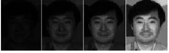
Figure 2: contrast enhancement images
3. PROPOSED METHOD
3.1 Su b -Ban d d eco mp o s ed mu lti-Scale retin ex
MSR is an extended SSR with multiple kernel windows of different sizes. MSR output is a weighted sum of several different SSR outputs . The MSR output for a single spectral component can be
represented as
𝑅𝑀𝑆𝑅(𝑥, 𝑦) = ∑ 𝑤𝑛. 𝑅𝑛(𝑥, 𝑦) (1) 𝑁
𝑛 =1
where
𝑅𝑛(𝑥, 𝑦) = 𝑙𝑜𝑔𝐼(𝑥, 𝑦)
− log(𝐹𝑛(𝑥, 𝑦) ∗ 𝐼(𝑥, 𝑦)) (2)
Here 𝑅𝑛(𝑥, 𝑦) ,denotes a retinex output associated with the n-the scale for an input image 𝐼(𝑥, 𝑦) .Note that gain wn is determined so that it can satisfy the
condition of The symbol “*” in Eq. (2) denotes the convolution operation and Nis the
number of scales. 𝐹𝑛(𝑥, 𝑦) Denotes a surround
function and is given by
𝐹𝑛(𝑥, 𝑦) = 𝐾𝑛𝑒(𝑥 2+𝑦2)
/𝜎𝑛2
(3)
Where is determined so that can satisfy
denotes the variance of the Gaussian kernel at then-the sub-band. Under the
condition every SSR, we can derive successive frequency sub-bands. Note that a small is suitable for enhancing fine details, whereas a Largent is suitable for improving tonality. Thus, it is important to select an appropriate value of an in the MSR. Based on this rationale, Jang et al. proposed an SD-MSR that consists of a modified logarithmic function, sub-band decomposition, space varying sub-band gain, and an automatic gain/offset control [16] (see Fig. 1). The modified log (mlog) is defined
as
𝑚𝑙𝑜𝑔(𝐼(𝑥, 𝑦) ) =
{ 𝑤𝐿log(𝐼(𝑥, 𝑦) + 1) 𝐼(𝑥, 𝑦) ≤ 𝜏
Available online:
https://edupediapublications.org/journals/index.php/IJR/
P a g e | 340Where τ is a user-defined threshold and D denotes an image dynamic range. For example, D is 256 for an
8-bit image
Figure 3: Block diagram of the conventional
SD-MSR
𝑤𝐿 And 𝑤𝐿 denote weighting parameters according to and are defined as
𝑤𝐿 = 𝜏 𝐷−1𝑙𝑜𝑔𝐷 log (𝜏+1) , 𝑤𝐿=
(1− 𝜏 𝐷−1)𝑙𝑜𝑔𝐷
log (𝐷−1) (5)
s a result, the mlog function of Eq. (4) enhances the contrasts of dark regions as well as bright regions. In this way, we can enhance image details both in highlights and shadows. Another feature of SD-MSR is to decompose the modified retinex outputs into nearly non-overlapping spectral bands. The following
equation accomplishes this sub-band decomposition:
𝑅̅1= 𝑅1 𝑛 = 1
𝑅̅𝑛= 𝑅𝑛− 𝑅𝑛−1 2 ≤ 𝑛 <
𝑁 (6)
As n increases, Rn corresponds to the low frequency region n more and more. Here, Rn is computed by
replacing the log of Eq. (2) With the mlog of Eq. (4) Next, the space vary in g sub-band gain at
then-the sub-band is defined as
𝑔𝑛(𝑥 ,𝑦) = ( 1 𝑁𝑅𝑛(𝑥,𝑦)+𝜀𝑔
)
1− 𝜎𝑛 𝜎𝑚𝑎𝑥+𝜀𝜎
(7)
Where
𝜎𝑚𝑎𝑥 =𝑛𝜖[1,2,3…𝑁]max 𝜎𝑛
𝑁𝑅𝑛(𝑥, 𝑦) = |𝑅̅𝑛(𝑥,𝑦)|
𝑅̅𝑛𝑚𝑎𝑥 (8)
In a high spectral band of small, they make the gain difference between pixels larger, especially for the
pixels with low 𝑁𝑅𝑛(𝑥, 𝑦) . This is because this spectral band has large high-frequency components representing image details. Meanwhile, they lower the gain difference between pixels in a high spectral band of large n to maintain the characteristics of a natural scene. Thus, using Eq. (7), the final enhanced
imageIis output as follows
𝐼′= ∑𝑁𝑛 =1𝑔𝑛𝑅̃ (9) 𝑛
3.2 Th e Pro p o s ed A lg o rith m
Available online:
https://edupediapublications.org/journals/index.php/IJR/
P a g e | 341by considering the temporal coherence of the input video sequence. The projected formula is differentiated from previous methods in the following 3 aspects. First, we tend to control the target power level mechanically. Second, we tend to avoid theflickering development by keeping the facility levels of adjacent images constant for video sequences. Third, we tend to come through time period process of the projected formula on a all-purpose graphics process unit (GPU) even for full
HD video sequences
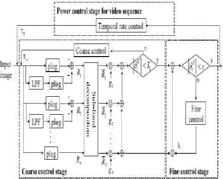
Fig u re 4: Block diagram of proposed method
Image nearer to the target power with distinction improvement and the second stage finely controls the image power such that it's terribly near the target power. If the input may be a video sequence, the ultimate stage adjusts the ability of every image so that it's the same as those of its neighbors by considering the temporal coherence of the input video sequence. The projected algorithmic program is differentiated from previous methods within the following 3 aspects. First, we have a tendency to control the target power level mechanically. Second,
we have a tendency to avoid the flickering development by keeping the ability levels of adjacent images constant for video sequences. Third, we have a tendency to bring home the bacon real-time process of the projected algorithmic program on a general purpose graphics process unit (GPU) even for full
HD video sequences.
A . Po wer M o d elin g in OLED Dis p lay
Before presenting an in depth clarification of the projected algorithmic program, we want to model power for associate OLED show. Dong et al. conferred a pel-based power model that estimates the ability consumption of OLED modules supported the red green-blue (RGB) specification of every pixel [21]. the ability consumption of associate OLED
show with K pixels, i.e., P is
𝑃𝑂𝐿𝐸𝐷 = 𝐶 + ∑𝐾𝑖=1(𝑓𝑅(𝑅𝑖) + 𝑓𝐺(𝐺𝑖)+𝑓𝐵(𝐵𝑖)) (10)
Also, we consider only the Y-componentbecause it dominates the entire overall power. Note that theY-component indicates the luminance theY-component in YUVcolor format. So we use the Y-component power consumption(YP) of an OLED display with
Kpixels [11] as
𝑌𝑃= ∑ 𝑌𝑖 𝛾
(11)
𝐾
𝑖 =1
Where γ is a parameter for gamma correction for a
given display device
B. Th e Pro p o s ed A lg o rith m
Available online:
https://edupediapublications.org/journals/index.php/IJR/
P a g e | 342and shadow regions. In other words, contrast in the dark region becomes high by increasing the intensity level of the pixels in the region, and contrast in the bright region also becomes high by decreasing the intensity level of the pixels in the region. However, the increase of the intensity values in the shadow region results in the increase in power consumption for the OLED display. So, for low power consumption as well as contrast enhancement, even in the shadow region, we redefine a so-called power-constrained log (plog) from them log of Eq. (4) as follows
𝑝𝑙𝑜𝑔(𝐼(𝑥, 𝑦)) =
{
𝜏𝑙𝑜𝑔𝐷𝑙𝑜𝑔 (𝛼𝐼(𝑥,𝑦)+1)
(𝐷−1)log (𝛼𝜏+1) 𝐼(𝑥, 𝑦) ≤ 𝜏
𝑚𝑙𝑜𝑔(𝐼(𝑥, 𝑦)) 𝐼(𝑥, 𝑦) > 𝜏
(12)
Therefore, the 𝑝𝑙𝑜𝑔 of Eq. (12) has the effect of controlling the increase in power consumption while partially lowering the contrast in the dark region.
From Eq. (7) and MSRs computed by 𝑝𝑙𝑜𝑔, i.e., {Rn}, we can derive the following output image
𝑅̃𝑡= ∑ 𝑔𝑛𝑅̀𝑛 (13) 𝑁
𝑛 =1
On the other hand, basin YP on Eq. (11), the power reduction ratio of an input image and its output image
is defined as follows
𝑝𝑡 = 1 −
𝑌𝑃(𝑅̂̂𝑡)
𝑌𝑃(𝐼) (14)
In this paper, 𝑅̅𝑛 can be computed with Eq. (15) as in [16].
𝑓(𝑋) = 𝑋𝑁= 𝑋 − 𝑚
𝑀 − 𝑚(𝐿 − 1) + 𝑙 (15)
Let 𝛿𝑡 denote the difference between 𝑝𝑡 and P as in Eq. (16)
𝛿𝑡= 𝑃 − 𝑝𝑡 (16)
Eq. (17) because such a condition indicates an excess
of power reduction over P.
𝜏𝑡 +1= 𝜏𝑡+
(𝐷 − 𝜏𝑡)
2
⁄ (17)
we increase τ relatively small as in Eq. (18) because
δCt weakly over runs P
𝜏𝑡 +1= 𝜏𝑡+
(𝐷 − 𝜏𝑡)
4
⁄ (18)
So we approach P by decreasing τ relatively small as in Eq. (19).
𝜏𝑡+1 = 𝜏𝑡+
𝜏𝑡
4
⁄ ( 19)
So we rapidly approach P by decreasing τ significantly.
𝜏𝑡 +1= 𝜏𝑡+
𝜏𝑡
2
⁄ (20)
On the other hand, the low-frequency region is rarely related to image details, but it dominates image power as a whole. So we try to approach P by finely controlling the proportion of the lowest-band MSR which may have most of the image power. In detail, we control the gain of RN as follows:
𝑅^= ∑ 𝑔
𝑛𝑅̅𝑛+ ( 𝑔𝑁+ 𝜆) 𝑁 −1
𝑛=1
Available online:
https://edupediapublications.org/journals/index.php/IJR/
P a g e | 343Where λ indicates a control parameter for the lowest-band MSR.λ, which is updated according to Eq. (22) enables the FCS to approach the target power with
little change of contrast
𝜆𝑡+1= 𝜆𝑡− 𝛿𝑡𝐹 (22)
4. SIMULATION RESULTS
Figure 5: Coarse control stage
Figure 6: Fine control stage (Iterations)
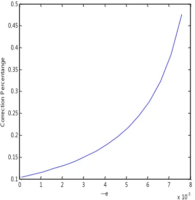
Figure 7: Fine control stage (Correction percentage)
0 50 100 150 200 250
0 0.5 1 1.5 2 2.5 3 3.5 4
Pixel Values
--P
lo
g
alp=1 alp=0.3 alp=0.1 alp=0.03 alp=0.01
0 0.001 0.002 0.003 0.004 0.005 0.006 0.007 0.008 0.009 0.01 1
1.5 2 2.5 3 3.5 4 4.5 5
e
It
e
ra
ti
o
n
s
0 1 2 3 4 5 6 7 8
x 10-3 0.1
0.15 0.2 0.25 0.3 0.35 0.4 0.45 0.5
---e
C
o
rr
e
c
ti
o
n
P
e
rc
e
n
ta
n
g
Available online:
https://edupediapublications.org/journals/index.php/IJR/
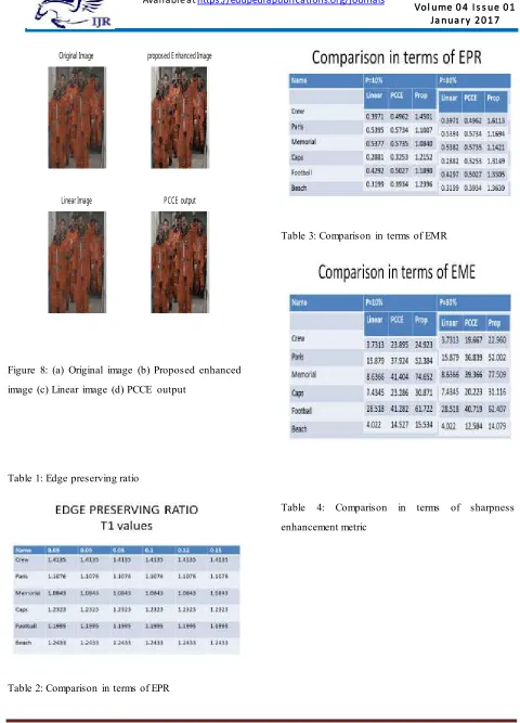
P a g e | 344Figure 8: (a) Original image (b) Proposed enhanced
image (c) Linear image (d) PCCE output
Table 1: Edge preserving ratio
Table 2: Comparison in terms of EPR
Table 3: Comparison in terms of EMR
Table 4: Comparison in terms of sharpness
enhancement metric
Original Image proposed Enhanced Image
Available online:
https://edupediapublications.org/journals/index.php/IJR/
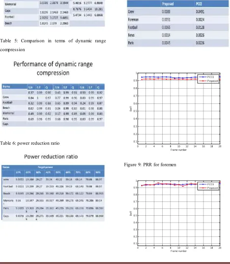
P a g e | 345Table 5: Comparison in terms of dynamic range
compression
Table 6: power reduction ratio
Table 7: Comparison of flickering artifacts
Figure 9: PRR for foremen
0 2 4 6 8 10 12 14 16 18 20
0.1 0.2 0.3 0.4 0.5 0.6 0.7 0.8 0.9 1
F rame number
D
e
lT
P CCE P roposed
0 2 4 6 8 10 12 14 16 18 20
0.1 0.2 0.3 0.4 0.5 0.6 0.7 0.8 0.9 1
F rame number
D
el
T
Available online:
https://edupediapublications.org/journals/index.php/IJR/
P a g e | 346Figure 10: PRR comparison for football video
Figure 11: Extension (BDQM)
A d vantag es : The different manufacturing process of OLEDs lends itself to several advantages over flat
panel displays made with LCD technology
5. CONCLUSION
This paper proposes Associate in Nursing SD-MSRbased image processing algorithm for fine power management in OLED displays. We designed a power-constrained log perform for effective power saving in dark regions. victimization the powerconstrained log function for SD-MSR Associate in Nursing Associate in Nursing adjective weight strategy proper for an input image, we tend to projected a coarse-to-fine power control mechanism for still pictures. Finally, we tend to given a power management theme for a constant power reduction ratio in video sequences by victimization temporal coherence in video sequences. Experimental results showed that the proposed algorithm provides higher visual quality than previous works, and a consistent power-saving magnitude relation while not the Specifically, the proposed algorithm provides at most twelve months and on average13% higher edge-preserving ratios than the state-of-the-art algorithm
(i.e., PCCE [11]). In addition, we tend to tried the possibility of real-time operation by accomplishing Associate in nursing entire execution time of nine ms per 1080p image.
REFERENCES
[1] J. Jang, S. Lee and M. Oh, “Technology development and production of flat panel displays in Korea,”IEEE Proc. J., Mag., vol. 90 no. 4pp.
501–513, Apr. 2002.
[2] K. Suzuki, “Past and future technologies of information displays,” inProc. IEEE IEDM, Dec.
2005, pp. 16–21.
[3] B. Young, “OLEDs—Promises, myths, and TVs, “Inform. Display,vol. 25, no. 9, pp. 14–17, Sep.
2009.
[4] H. D. Kim H. J. Chung, B. H. Berkeley, and S. S. Kim, “Emerging technologies for the commercialization of AMOLED TVs,”Inf. Display,
vol. 25, no. 9, pp. 18–22, Sep. 2009.
[5] W.-C. Cheng and M. Pedram, “Power minimization in a backlitTFT-LCD display by concurrent brightness and contrast scaling,”IEEETrans. Consume. Electron. vol. 50, no.
1, pp. 25–32, Feb. 2004.
[6] P. Greef and H. G. Hulze, “Adaptive dimming and boosting backlight forLCD-TV systems,” inside Symp. Dig. Tech. Papers, May 2007, vol. 38, no. 1,
pp. 1332–1335.
[7] L. Kerensky and S. Daly, “Distinguished paper: Brightness preservation for LCD backlight reduction,” inSID Symp. Dig.
Tech.Papers, Jun. 2006, vol. 37, no. 1, pp. 1242–124.
0 2 4 6 8 10 12 14 16 18 20
39 40 41 42 43 44 45
F rame number
B
D
Q
M
Available online:
https://edupediapublications.org/journals/index.php/IJR/
P a g e | 347[8] C.-C. Lai and C.-C. Tsai, “Backlight power reduction and image contrast enhancement using adaptive dimming for global backlight applications,”IEEE Trans. Consume. Electron. vol.
54, no. 2, pp. 669–674, May 2008.
[9] S. I. Cho, S.-J. Kang and Y. H. Kim, “Image quality-aware backlight dimming with color and detail enhancement techniques,”IEEE J.Display
Technol., vol. 9, no. 2, pp. 112–121, Feb. 2013.
[10] P.-S. Tsai, C.-K. Liang, T.-H. Huang and H. H. Chen, “Imageenhancement for backlight-scaled TFT-LCD displays,”IEEE Trans.Circuits Syst. Video Technol., vol. 19, no. 9, pp. 574–583,