Field Problem of Cabin Mounting Bracket of Load
King Pride
1
M MEGHANA,
2K VINOD REDDY
1 Pg Scholar,Department of Mechanical Engineering, elleniki college of enginnering and technology
2.Asst.Prof, Department of Mechanical Engineering, elleniki college of enginnering and technology
ABSTRACT
In an automobile industry while designing
the components, the most critical aspect
considered is the compactness and the
weight of the component. According to the
Newton’s 2 law of motion the energy
required to accelerate the vehicle depends
upon the mass of the automobile. In the
structural point of view the automotive materials
should have more strength to weight ratio. One
of the structural automotive vehicles and which
are more in number are the mounting brackets.
Mounting brackets are generally used support
the structural component and electronic
components such as batteries, seats, cabin,
chassis, rear body and also it should support the
external load such as passengers. Since it is very
much needed to reduce the weight and therefore
it is to be redesigned or optimized for minimum
weight without sacrificing the functionality. The
most common material used for the structural
components is structural steel. The bracket is
designed according to the specifications of the
mountings without considering any other
factors. Analysis will be performed for
Existing and New modified designs. The
most important factors that are concentrated
are stress distribution and deflection. The
design structure is optimized for its
topology. The reviewed design is analyzed
and the better design for the minimum
weight is considered, according to the
optimized design parameters the structure is
rebuilt. Modeling is the representation of
the system or a part of the system in a
suitable for demonstrating behavior of the
system. Simulation involves subjecting the
models to various inputs or environmental
conditions to observe the behavior and thus
explore the nature of the results. That might
be obtained from the real world system.
Simulation is the manipulation of the model.
It may involve mathematical model
subjected to mathematical disturbance
functions that simulate expected service
conditions or it may involves software
which are built on the basis of the finite
element techniques like Ansys, Nastran,
Hypermesh, LS-Dyna etc… loads and
constraints are used as boundary conditions
and required results are extracted from the
Software tools. In this project, an attempt
has been made to produce optimized design
of a mounting bracket.
1.INTRODUCTION:
This bracket that's getting used within the
vehicle weights regarding 1KG. Four
mounting brackets area unit wont to
support the complete cabin assembly. Total
weight of the cabin assembly is 650
kilogram with four passengers. 2 brackets
area unit placed at the front facet of the
vehicle cabin and remaining 2 area unit
placed at the rear facet. During this Project
work static and dynamic analysis of the
mounting bracket was carried out. Within
the static analysis solely the load of the
cabin with passenger’s weight, vertical load,
cornering load and acceleration load was
taken. In dynamic analysis natural
frequencies premeditated. Brackets area unit
meant for carrying hundreds, supports
structures, bearings that support the shaft.
1.1. STYLES OF BRACKETS
Wall Brackets
Wall brackets area unit mounted to The wall for the aim supporting bearings, which either
could also be solid with the brackets.
Pillar Brackets
These area unit wont to support a horizontal shaft from a pillar wherever there's no enclose
the method of wheels or pulleys on the shaft
Mounting Bracket
These area unit principally employed in automotive and part industries for
structures like electronic product like batteries, sensors in automobile for fixing the body to
the chassis, for fixing the auxiliaries and for fixing the Cabin to the Chassis.
2.LITERATURE REVIEW:
Balamurugan [1] used shell elements and
finite element simulation method with beam
for modeling of military-tracked vehicle. An
Eigen value analysis has been done to
estimate natural modes of vibration of the
vehicle. The dynamics response of such
important location is obtained by carried out
by a a transient dynamic analysis using
implicit new marl beta method.
Curtis .F. Vail [2], this paper illustrates the
use of F.E.Methods for modeling
automotive structure for their dynamic
characteristics. The results obtained using
F.E.Computer models were within 10% of
test results. Data reparation typical
F.E.Model, outline of the analysis and the
display of the data in the form of movie is
covered.
Dr. Pawlowski [3] suggestions from his
book Design Engineering and body
construction has been used in this for
designing the floor.
J.L.Hedges, C.C.Norville, O.Gurdogan[4],
in these paper coarse and refined
idealizations of the structure was analyzed
by considering the effect of manufacturing
tolerances. Stresses wee predicted under
bending and torsion loads. Predictions
follows the measured deflection curve but
and sensitive to the idealization of the beam.
Karuppaiah [5] had done vibration analysis
of a light passenger vehicle using a half-car
rigid model and a finite element model. It
has found that the results from the rigid
body model are slightly in the lower side as
compared to those from finite element
model. Parametric study has also been
carried out to study the effect of different
parameters on vibration levels in the vehicle.
The advantages and disadvantages of the
non-contact method for road profile
measurement have also been brought out.
Karuppaiah [6] applied for a passenger
vehicle, finite element method for model
and vibration/stresses analysis. The block
lancozs method has been successfully used
for the model analysis. The experiments
were carried out using piezo-electric
accelerometers and strain gauges to measure
the vibration and strain gauges to measure
the vibration and strain levels at critical
points of vehicle. The prediction values
through F.E.M were match well with
carried out with a view to find the optimum
suspension/tyre characteristics for maximum
ride comfort in the vehicle.
Kiyoshi Miki [7]. This paper presents the
outline of a theoretical analysis of bending
& torsional vibration of passenger car
bodies. Body structure is simulated by a
framework with tension rigs & additional
panel stiffness’s. The framework is a
three-dimensional model for the bending and
torsional vibration,or two-dimensional for
the bending vibration, and is analyzed by the
lumped mass system. All input data are
calculated from drawings, and therefore
characteristics of body structure are forecast
&controlled in the design process.The
analysis is applicable to coupled vibration &
forced vibration problems.
Mukul Shukla [8], the work done is finite
element analysis of vikram chassis frame
under critical loads, simulating Indian load
conditions. Modeling is done using deem,
shell and rod and then analysis simple beam
and rod elements are used, but analysis
using 3 – D tetrahedral element is better and
realistic approach as stated by the author. In
his paper Mukul Shukla, in static analysis
maximum stress is with in the specified
limits and a factor of safety of 2-3 is
obtained and the maximum stress occurs in
the leaf spring joints and author says that
present analysis is inadequate for leaf
springs, as springs, as springs an more
susceptible to fatigue failure than static and
dynamic failure.
R.Ali, J.L.Hedges, B.Mills [9], in this paper
Finite element techniques are applied to
determine the static properties of and
automobile body floor,
Robert .J. Melson[10], This paper reviews
the success of efforts to predict linear static
dynamic and non-linear transient behaviors
of car components and structural systems. It
relates the analysis accuracy to essential
features of justify boarder use of numerical
methods in the industry. Modeling from
engineering drawings and coupon test data
cannot be expected to yield behavior pre
dictions with an error of less than five
percent.
3.IMPLEMENTATION:
".In this Project work, It got to style the
mounting bracket in such manner that it
ought to face up to for road load conditions.
each thickness and therefore the material
area unit studied for this style. because the
project deals with the look of mounting
bracket, the prevailing style is analyzed and
the reference for the current project work.
the most downside is that, the mounting
bracket thickness ought to be optimized for
its minimum weight and even be taken care
that stress ought to be below yield stresses.
The main aim of this project work is to form
3d model of the prevailing bracket as per
second measurements and Hyper Mesh &
Ansys has got to be performed on this model
to watch stresses developed at bolt regions
area unit like sensible testing.Similerly New
style one & New style two has got to be
created and meshing and analysis has got to
be performed finally the optimisation got to
performed to cut back the stresses at weak
components within the mounting bracket
and overall weight of the mounting bracket.
this can be the goal of the project work.
Following area unit the image of the sensible mounting bracket failure underneath high stresses
and geometric models of existing new style 1&2has been created.
The field issues of mounting bracket image area unit shown within the chapter2. Refer
Plate one.1, 1.2 and 1.3.
The elaborated drawings of the prevailing and changed styles area unit shown within the
following figures three.1, 3.2 and 3.3 severally.
Geometric models of the prevailing and changed styles area unit shown within the
following figures three.4, 3.5 and 3.6 severally.
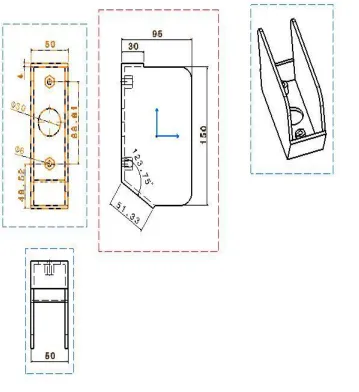
Fig 3.2 first modified design of the mounting bracket (All Dimensions are in mm)
Fig 3.2 shows the detail Description of the new design-mounting Bracket, the modifications are
1. Straighten the two legs of the bracket.
2. Adding the extra plates at front and rear faces of the mounting bracket.
3. Increased the thickness from 3.2 mm to 4 mm.
4. Weight is increased from 1 Kg to 1.2 Kg.
And the modifications has been done in the new drawing 2 are similar to above drawing 1 but
additionally fillets were added at the corners of the bracket as shown in the following figure.
Fig 3.3 shows the detail description of the new modified design of the mounting bracket.
4.RESULT:
The finite element modeling and analysis is
used to study the stress variation at different
points of the mounting bracket and also the
deflection at various locations of the
mounting bracket having various thicknesses
with single material. Topology optimization
is also carried out to extract the best design
and to reduce the weight of the mounting
bracket.
Two parameters studied in this Project work
are one is the thickness and the other one is
the weight of the mounting bracket to rectify
the field problem.
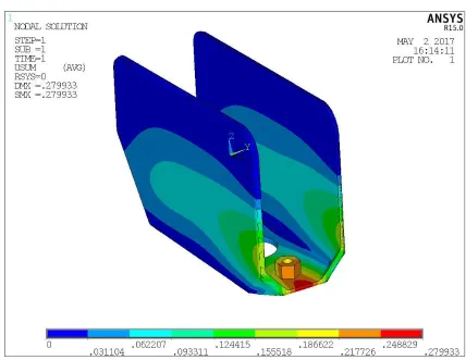
4.1 STATIC ANALYSIS RESULTS
Fig.4.1. Deformation induced in the Mounting Bracket of Existed design made of STEEL-HR-1DD
deformation in the Mounting Bracket due to
with a load of 750 N on each bolt is applied, the
maximum deformation is observed is 0.27993
mm for the STEEL-HR-1DD material.
5.THE CONCLUSION THAT
ARE DRAWN FROM THE
PRESENT WORK ARE
From the analysis the bracket with
that of 3.2 mm thickness weighing 1
Kg and 4 mm thick bracket weighing
1.2 Kg and the final optimized
bracket with 4 mm thick weighing 1
Kg. The more strength is gained for
4 mm thick bracket after its
optimization.
The induced deflections of different
thickness in all the brackets are very
small and are less than 0.1 mm for
all the cases and hence these are all
rigid.
The stresses induced are well under
the allowable stresses and
maintaining high factor of safety.
The thickness of the optimized
bracket 4mm is reduced from 1.2 Kg
to 1 Kg.
Cost of the Mounting bracket
remains same when the optimized
design compared with Existing
Design. And the safety of optimized
design is increased.
Finally the weight of the both the
Optimized design and Existing
Design is same but the deformation
and stresses were better than the
Modified Design as well as Existing
Design and therefore the Optimized
design should be implemented. From the dynamic point of view the
amplitudes were well within its
limits, Hence the design is safe for
the dynamic stability. Compared to
other brackets, brackets that are
made of CFRC material had superior
perforamance.
FUTURE SCOPE
It is suggested to run the fatigue
analysis on the modified design to further
Optimize the shape and size.
REFERENCES:
1. Alf Samuelsson and Nils-Erik
Wiberg: Finite element adaptively in
dynamics and elasto-plasticity”.
Volume “The finite element method in the 1990’s, Springer-Verlag, 1 pp.
(1991).
2. C.C. Menzemer, L. Fei, T.S.
connection elements in Aluminum
Alloy 6061, Transactions of ASME,
Vol.121, Sep 1991, p348-357.
3. Fernandes, Cmtt, Leitao, Vma,
Vasarhelyi, a., Thin Plate Bending
Analysis Using An Indirect Trafftz
Collocation Method, computer
Assisted Mechanics and Engineering
Sciences, 8, 1-16, 2001.
4. Hao Jin, Kjell Mattiasson, Kenneth
Runesson and Alf Samuelsson: The
boundary element method for
elasto-plastic large deformation problems,
International Journal of Numerical
Methods in Engineering, vol. 25, pp.
165-175, (1987).
5. J. Newnham, L. Curley, Bolted joints
under tensile loads: The effect of
torsion in the Bolt on in-service
clamping loads, Transactions of
ASME, vol.15, March 1993, p36-40.
6. Kjell Mattiasson, Lars Bernspong
and Alf Samuelsson: Solution of
quasi-static, force-driven problems
by means of a dynamic-explicit
approach and an adaptive loading
procedure, Engineering
Computations, vol.13, pp. 172-189,
(1996).
7. Mats Ander and Alf Samuelsson:
Finite Element analysis of
Geometrically Non-Linear Structures
Using Translational Variables,
International Journal for Numerical
Methods in Engineering, Vol. 46,
pp.1367-1383, (November 1999).
8. Magnus Kjellman and Alf
Samuelsson: A high-precision
adaptive procedure for solving
Kirchhoff plates, in Discretization
Methods in Structural Dynamics,
(Eds. Kuhh, G. and Mang H.),
Springer, pp. 125-133, (1990).
9. Nina Lauterstajn-S and Alf
Samuelsson: Further discussion on
four-node isoperimetric quadrilateral
elements in plane bending,
International Journal for Numerical
Methods in Engineering, vol. 47, pp.
129-140, (2000).
10. Ansys and Hyper mesh user