Centralized Control Station
John Bazil J A1, Rahul Khanna N M2, Dinesh P3, Narren M4, Prakash S5 Student, Department of ECE, Jansons Institute of Technology, Coimbatore, Tamil Nadu, India
Student, Department of ECE, Jansons Institute of Technology, Coimbatore, Tamil Nadu, India
Student, Department of ECE, Jansons Institute of Technology, Coimbatore, Tamil Nadu, India
Student, Department of ECE, Jansons Institute of Technology, Coimbatore, Tamil Nadu, India
Assistant Professor, Department of ECE, Jansons Institute of Technology, Coimbatore, Tamil Nadu, India
ABSTRACT: Smart city is the designation given to a city that incorporates information and Communication Technologies to enhance the performance of urban services. It uses smart system characterized by the interaction between infrastructure and technology. Now a day, Technology is improving rapidly which can be useful for the cities to work smart and reduce the work force. A city consists of many departments to monitor and control different sectors. The project mainly focuses on prompt actions, timeliness and hence reduces the work force. The objective is to control all those sectors in the city from one centralized station. The Dams, Traffic signals, Pipelines and the streetlights are controlled from one place where the parameters, which are used as criteria controlling those, can be obtained from each of the sources with the help of the sensors. This technology uses an IoT platform such as Adafruit. Each sector sends its state to the control station from which the authorized persons can control them.
KEYWORDS: Adafruit, Dams, IoT, Pipelines, Sensors, Smartcity, Streetlights, Traffic signals.
I. INTRODUCTION
Technology is the main invention that gathers the techniques, skills, processes and knowledge to make the urban services better. Now-a-days technology is developing rapidly leading a way for a great future. The assumption is that the future will be with more technology with cities, which incorporates information and communication Technologies to enhance the quality and performance of urban services.
Internet of Things (IoT) is the interconnection of different devices via the Internet, embedded in everyday objects, enabling them to send and receive data. It is a computing concept that describes the idea of the connection of everyday physical objects and the internet and being able to identify themselves to other devices.
II. EXISTING SYSTEM
The existing system is that the Dam, Pipeline, Solar street lights, Traffic signal controller, etc. are controlled manually. In Dams, the water level is measured in TMC (Thousand Million Cubic feet). To measure the water level, the depth is observed by a person and reports it to the higher official. Hence, the head of the department should get permission to control the Dam gates which is a long process. In Traffic signals, a technician changes the code of the signal in which the person should visit the area and connects the signal controller with the system. In pipelines, the employee manually opens or closes the pipeline. Each sector is monitored and controlled in that region. This requires more workforce and time.
III. PROPOSED WORK
The project consists of four modules which are connected to the MQTT server via internet.
1. Dam
2. Pipeline
3. Streetlight
4. Traffic Signal
As far as MQTT server is concern, each of the module consists of a publish value (the sensor value) and a subscribe value (the output from the Adafruit MQTT server). The MQTT acts as a broker for connecting multiple devices. The Adafruit webpage consists of many blocks for input and output. The sensor units in the projects send the data from the node mcu esp8266. A person from the control station controls the controllable units. The control signals are transmitted via internet and the signals are received by the nodemcu esp 8266. The MQTT server is the key to connect all the devices through the internet. Each of the module is connected to the nodemcu esp8266 with which they are monitored and controlled by the MQTT server. The project uses Adafruit MQTT server as it is user friendly and open source server.
A. Dam:
For Dams, a slider indicates the water level and two separate momentary buttons controls the Dam gate. The Ultrasonic sensor measures the water level. A dc gear motor controls the Dam gate. The L293 motor driver is used to drive the motor in clockwise and anti- clockwise directions.
B. Pipeline:
For Pipelines, a gauge indicates the water flow rate and an ON- OFF switch controls the valve. The water flow is measured using flow sensor, which works under the principle of Hall Effect. The water flow can be controlled by a Solenoid valve which opens when 12 to 24V is given. Hence, for a switch to withstand 12V to 24V, a Relay module is used.
C. Street lights
For Streetlights, a small gauge indicates the light intensity and ON- OFF switch controls the Streetlights. The LDR module (Light Dependent Resistor) measures the light intensity.
D. Traffic light Controller:
For Traffic Signal, a text block in the Adafruit server
sends the string to the controller. The controller receives the string, which is of integer values separated by spaces. According to the string received, the green signal will glow. The string received is the delay time of which the green light glows.
Figure 2: Adafruit server [Centralized Control Station]
The figure 1 represents the Adafruit server, which serves as the platform to monitor and control all the modules. The
IV.SYSTEM COMPONENTS
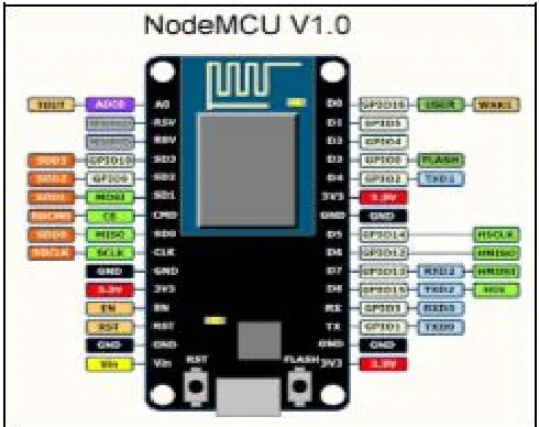
A. NodeMCU ESP8266:
The Nodemcu esp8266 is a microcontroller designed by Expressive Systems. It has an inbuilt Wi-Fi module. Lua scripting language is used in this firmware. It is a Single-board microcontroller. It has XTOS operating system. It has 128KB memory and 4MB storage. It is SoC integrated with Tensilica Xtensa LX106 core. It is widely used in IoT applications.
Figure 3: Nodemcu esp8266 pin configuration
• Inbuilt Wi-Fi module
• Voltage:3.3V.
• Wi-Fi Direct (P2P), soft-AP.
• Current consumption: 10uA~170mA.
• Flash memory: 16MB max (512K normal).
• Integrated TCP/IP protocol stack.
• Processor: Tensilica L106 32-bit.
• Processor speed: 80~160MHz.
• RAM: 32K + 80K.
• Output power is +19.5dBm in 802.11b mode
• Supports 802.11 b/g/n.
B. Module 1- Dam:
1. Ultrasonic sensor:
Ultrasonic sensor works under the principle of ultrasonic reflection in which the ultrasonic waves are transmitted, reflected by the obstacles and received. The time form the transmission to the reception is noted, which gives the distance of the object. Here the ultrasonic sensor is used to find the depth of the water in the dam.
The distance is measured using a formula Distance = ½*T*C
Where T- time between emission and reception C- Speed of sonic waves
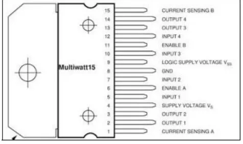
2. Motor Driver (L298):
A motor driver is current amplifier that takes a low current signal as a control signal and controls the motor, which drives in high current. The main function of the motor driver is to convert low current to high current signals.
The L298 is an integrated monolithic circuit Multi watt and powerSO20 package. Contains two enable pins.
Operating voltage: 4.5 to 36V. Compactible.
High Noise Immunity Input. Output current 1A per channel
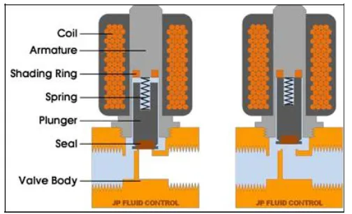
At rest position, the plunger is closed. When an electric current is applied, it creates a magnetic field, which simultaneously creates a force on the plunger. As a result, the plunger is opened.
• Voltage- 12V to 24V • Current- 600mA
• Works under the principle of magnetic effect.
• When there is 12V supply, the valve due to magnetic effect moves such that it opens the valve. •
C. Module 2- pipeline:
1. Water flow sensor (YF- S201):
The water flow sensor works under the principle of Hall Effect. It consists of a turbine that rotates when the water flows. The turbine is attached to a magnet in which the Hall Effect sensor counts the rotation. This ultimately gives the water flow rate.
• Works under the principle of Hall Effect.
• Voltage – 5V , Current- 15mA
• Maximum water pressure- 2.0MPa
• Pulse frequency is measured using the Hall Effect sensor and it is converted to Liters per minute.
• Formula:
Flow rate= Pulse frequency/7.5.
Figure 6: solenoid valve working
D. Module 3- Streetlights:
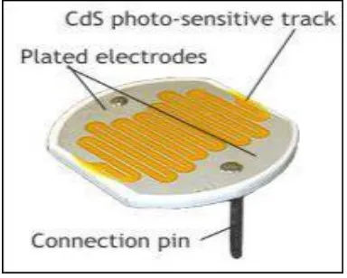
1. LDR Module:
LDR is a photo resistor in which the value of resistance changes according to the intensity of light. It works under the principle of photoconductivity. Here, when the light intensity decreases, the resistance also decreases. As a result, the conductance increases. When the light intensity increases, the resistance also increases. As a result, the conductance decreases.
• Voltage- 3.3V to 5V , 15mA.
• Small, cheap and easy to interface with MCU.
• Daylight = 5k ohms.
• Threshold = 1-5 M ohms.
Figure 5: Water flow sensor working
2. Solenoid Valve:
A solenoid valve works under the principle of electromagnetic mechanism. It consists of electric coil with a ferromagnetic core in the center called as ‘plunger’.
Figure 7: LDR
E. Module- 4- Traffic signal controller:
ATmega328 has three types of memory:
Flash memory: 32KB nonvolatile memory. This isused for storing application, which explains why you don't need to upload your application every time you unplug arduino from its power source.
SRAM memory: 2KB volatile memory. This isused for storing variables used by the application while it's running.
EEPROM memory: 1KB nonvolatile memory.This can be used to store data that must be available even after the board is powered down and then powered up again.
Figure 8: Arduino pin configuration
LEDs are used for the traffic lights. The Arduino receives a string of integers from the server through Nodemcu esp 8266. According to the data received, the LEDs switches on and off which makes the traffic signal.
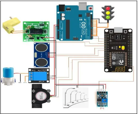
Figure 9 shows the component connection of the project. Each of the module is connected to nodemcu esp8266 with which the data are shared with the server through the internet.
V. CONCLUSION
This project can be a breakthrough for the smart city for which every devices can be controlled and monitored from a single place. The future will be full of AI (Artificial Intelligence) and the project can be modified such that it can be monitored and controlled by the Artificial Intelligence. The Internet of Things makes a sophisticated way for monitoring and controlling of many devices. The government can implement this project as a real time and the workforce can be ultimately reduced.
VI. FUTURE ENHANCEMENT
In future, the project can be extended to vast areas. Each industry can be monitored and controlled from one place. There will be no need for the presence of humans in the industry. It can also be a fully automated industry. Police and military force can be taken over by robots controlled by from a single station or by AI.
REFERENCES
[1]
“IOT BASED SMART CITY USING RASPBERRY PI” by Aishwarya R.Hujare, Namrata C.Repe,Rutuja M.Salokhe at 8th
National conference on “Emerging trends in Engineering and Technology”.
[2]Andrea Zanella, Nicola Bui, Angelo Castellani,LorenzoVangelista,Michele Zorzi(2014) “Internet of Things for Smart Cities”,IEEE Internet of Things Journal,Vol.1,No.1, pp. 22-32.
[2]Basavaraju S R (2015) “Automatic Smart Parking System using Internet of Things (IOT)”, International Journal of Scientific and Research
Publications, Vol.5, No.12, pp. 629-632.
[3] Vinay Sagar K N, Kusuma S M: “Home Automation Using Internet of Things”, International Research Journal of Engineering and Technology
(IRJET) Volume: 02 Issue: 03 | June-2015.
[4] Shifeng Fang, LiDaXu. An Integrated System for Regional Environmental Monitoring and Management Based on Internet of Things[J], IEEE
TRANSACTIONS ON INDUSTRIAL INFORMATICS,VOL.10,NO2,MAY2014.
[5] Archana. G, Aishwarya N, Anitha J “Intelligent Street Light System” International Journal of Recent Advances in Engineering & Technology,
Vol-3, Issue-4, 2015.
[6]AkshayBalachandran, Murali Siva, V. Parthasarathi, Surya and Shriram K. Vasudevan “An Innovation in the Field of Street Lighting
System with Cost and Energy Efficiency”Indian Journal of Science and Technology,Vol-8, August 2015.
[7] Rahul B. Pendor , P. P. Tasgaonkar " An IoT Framework for Intelligent vehicle monitoring System", International Conference on
![Figure 2: Adafruit server [Centralized Control Station]](https://thumb-us.123doks.com/thumbv2/123dok_us/7761547.1274329/3.595.196.425.468.668/figure-adafruit-server-centralized-control-station.webp)