Dielectric Circular Waveguide Loaded with
Dielectric Material
Dimple N. Agrawal
1, Raj Hakani
2PG Student, Dept. of Electronics and Communication, Silver Oak College of Engineering and Technology,
Ahmedabad, Gujarat, India1
Assistant Professor, Dept. of Electronics and Communication, Silver Oak College of Engineering and Technology,
Ahmedabad, Gujarat, India2
ABSTRACT: Electromagnetic waves is very strong waves which is used for transmission of signals from one place to other, to guide these electromagnetic transmission line and waveguide are used. The main concern for the transmission is the selection of waveguide and its physical structure, material and dimensions. In Convectional Wave guide has more attenuation loss, return loss and insertion loss due to the presence of the small corner. To obtain desired results different dielectric material and structures plays the important role in waveguide. In this work an attempt has been made a design Dielectric Circular waveguide for Ku-Band (12GHz to 18GHz) . This paper analyze the different parameter of Dielectric Circular waveguide loaded with dielectric material like (Cut off frequency, Return loss, Insertion loss) with the help of simulation in CST. Compare the parameter like (Return loss and Insertion loss) of Dielectric Circular waveguide loaded with different dielectric material.
KEYWORDS: Waveguide, Dielectric Circular Waveguide, Losses, CST Simulation .
I.INTRODUCTION
Waveguide is a metallic structure which is used for a transmission of an electromagnetic energy between two points. There are basically two types of waveguide. A metal waveguide and a dielectric waveguide. Metal waveguides are typically one enclosed conductor in which an insulating medium is filled while a dielectric waveguide consists of multiple dielectrics[1]. Hollow waveguides are widely used for Monostatic radar level measurements in the industrial environment, and satellite communications. Conventional waveguide like Rectangular waveguide has number of losses due to small corner at the end while Circular waveguide with only conduction material has number of conducting losses, insertion loss which can reduce the power of the signal and signal strength. While taking about long distance communication, need of the high power signal and strengthen signal for transmission. A dielectric is a nonconductor of electric current. Dielectric constant and finite conductivity is solution for lossless dielectric guides for zero conductivity and the hollow metallic waveguide for microwave technology [2-4] so, dielectric waveguide is better than the circular and rectangular waveguide. Different material has different permeability, permittivity and dielectric constant which can produce better results for return loss and insertion loss.
II.PROPERTIES OF DIECTRIC CIRCULAR WAVEGUIDE
Metal waveguides normally take the form of an enclosed conducting metal pipe[1]. The waves propagating inside the metal waveguide may be characterized by reflections from the conducting walls. While the dielectric waveguide consists of dielectrics only and employs reflections from dielectric interfaces to propagate the electromagnetic wave along the waveguide.
λg... Wavelength of Waveguide
λc... Cut-off Wavelength (dominant mode)
fg... Frequency of Waveguide
fc... Cut-off Frequency (dominant mode)
r... Waveguide Radius d... Waveguide Diameter µ... Permeability of Material ε... Permittivity of Material
𝜒𝑚𝑛′ ... nth (n=1,2,3,…) zero of the derivative of the Bessel function
[A] Mode of Dielectric Circular Waveguide
Modes of the circular waveguide shows that the Electric field is perpendicular to the length of waveguide and there is no any Electric lines parallel to the direction of propagation. The dominant mode of the circular waveguide is TE11 where m=1 and n=1. For complete one cycle „m‟ and „n‟ shows the no. of ½ cycle variations of the fields
along the diameter[5]. In this mode, waveguide shows the lowest cut off frequency required for operating. The cut-off wavelength of a circular guide is 1.71 times the diameter of the waveguide. In the circular waveguide, the E field is perpendicular to the length of the waveguide with no E lines parallel to the direction of propagation. Thus, it must be classified as operating in the TE mode.
[B] Cut-off Frequency
Waveguide work as high pass filter, it means that below the cut-off frequency waveguide cannot pass any wave through it. For Dielectric Circular Waveguide the cut-off frequency[1] of the mn mode is given by
(𝑓𝑐)𝑚𝑛 =
𝜒𝑚𝑛′
2𝜋𝑟 µ𝜀
In this paper, dominant mode is considered so, cut-off frequency[1] is given by
(𝑓𝑐)𝑚𝑛 =
1.841 2𝜋𝑎 µ𝜀
[C] Cut-off Wavelength
The cut off wavelength is defined as the maximum wavelength of the waves to be transmitted through the waveguide. All the wavelengths greater than λc are attenuated and those which is less than λc are allowed to
propagate inside the waveguide. For Dielectric Circular Waveguide the cut off wavelength[1] is given by
(𝜆𝑔)𝑚𝑛 =
𝜆
1 − (𝜆𝑐
𝜆)2
[D] Return Loss
The ratio of the reflected power from a load, to the incident power on that load, is known as return loss. Typically, return loss is expressed in dB [1]
𝑅𝑒𝑡𝑢𝑟𝑛 𝑙𝑜𝑠𝑠 = −10 log10
𝑃𝑟𝑒𝑓
𝑃𝑖𝑛𝑐
𝑅𝑒𝑡𝑢𝑟𝑛 𝑙𝑜𝑠𝑠 = −10 log10 Ґ𝐿 2
index of material. The higher the return loss is means the lower reflection and the connection is better or no mismatch.
[E] Insertion Loss
The reciprocal of the ratio of the signal power delivered to that load, to the signal power delivered to the load before insertion. Insertion loss is usually expressed in dB
𝐼𝑛𝑠𝑒𝑟𝑡𝑖𝑜𝑛 𝑙𝑜𝑠𝑠 = 10 log10
𝑃𝑇
𝑃𝑅
III. SIMULATIONS AND RESULTS [A] Dielectric Circular Waveguide Loaded with Air as Dielectric Material
The Dielectric Circular Waveguide is designed for Ku band (f0 = 15GHz) with Inner radius is 6.5 mm, Outer
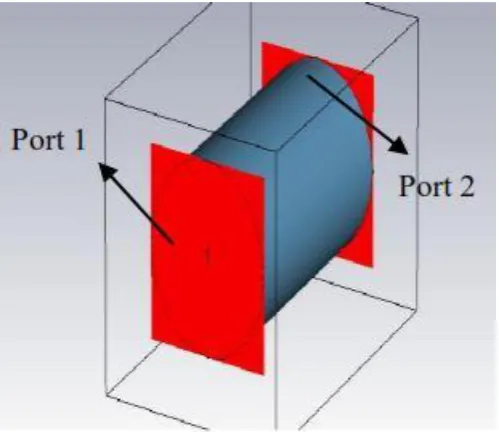
radius is 7.5mm and length is 21mm, Teflon material and air is a dielectric material. This waveguide was designed and simulated in CST v10.0 software which was shown in Figure- 1.
Figure 1 Simulation of Dielectric Circular Waveguide with Teflon Material
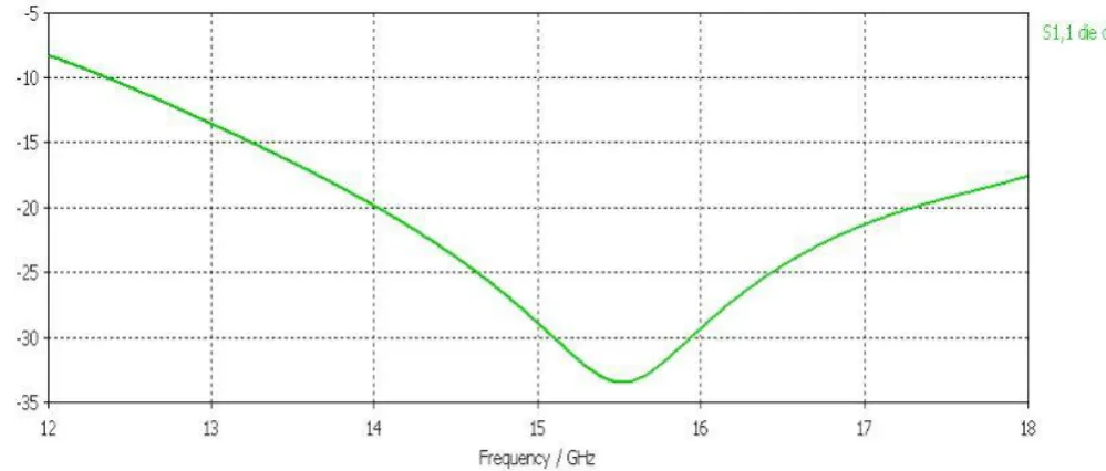
Figure 2. Simulated Return loss of Dielectric Circular Waveguide with Teflon Material
The Simulated insertion loss (in dB) for the design Dielectric Circular waveguide is presented in Figure 3. It can be seen that the insertion loss between -0.01dB to -0.015db for Ku band, while for operation frequency 15 GHz insertion loss is -0.01365 dB.
Figure 3. Simulated Insertion loss of Dielectric Circular Waveguide with Teflon Material
[B] Dielectric Circular Waveguide Loaded with Other Dielectric Material
The Dielectric Circular Waveguide is designed for Ku band (fo = 15GHz) with Inner radius is 6.5 mm, Outer
material loaded as a dielectric material inside the waveguide. This waveguide was designed and simulated in CST v10.0 software which was shown in Figure- 4.
Figure 4 Simulation of Dielectric Circular Waveguide Loaded with Dielectric Constant Material
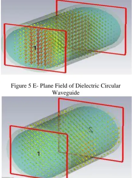
Experimental E- Plane field and H-Plane field pattern are shown in Figure 5 and Figure 6 respectively.
Figure 5 E- Plane Field of Dielectric Circular Waveguide
Figure 6 H- Plane Field of Dielectric Circular Waveguide
Port 1
The Simulated return loss (in dB) for the design Dielectric Circular waveguide loaded with dielectric material is presented in Figure 7. It can be seen that the return loss for all loaded dielectric material is below -9.010 dB for Ku band, while for operation frequency 15 GHz return loss for all loaded dielectric material is below -20 dB.
Figure 7 Comparison of Return Loss for Dielectric Circular Waveguide Load with Material
The Simulated insertion loss (in dB) for the design Dielectric Circular waveguide is presented in Figure 8. It can be seen that the insertion loss for all loaded dielectric material is between -0.01dB to -0.015db for Ku band, while for operation frequency 15 GHz insertion loss is -0.01365 dB.
Table I. Color Representation for seven better material loaded in waveguide
Sr. No Outer Material Inner Material Color Shown in graph
1 Teflon Air
2 Teflon Mica
3 Teflon Duriod (5880)
4 Duriod (5870) Rogers (3006)
5 Teflon Duroid (5870)
6 Teflon Lead Glass
7 Rogers (R03003) Lead Glass
Table II. Comparison Table of Return loss and Insertion loss for Different Loaded Dielectric Material
Sr. No Outer Material Inner Material Return Loss (dB) Insertion Loss (dB)
1 Teflon Air -28.88789 -0.01253
2 Teflon Duriod (5880) -24.73434 -0.060229
3 Duriod (5870) Rogers (3006) -27.21203 -0.112761
4 Teflon Rogers (R03003) -23.76324 -0.42657
5 Teflon Duroid (5870) -36.88378 -0.20463
6 Teflon Lead Glass -27.55514 -0.28813
7 Rogers (R03003) Lead Glass -34.14601 -0.34098
8 Teflon Rogers (R03006) -26.66256 -0.71002
9 Teflon Dupont -36.8837 -0.20463
10 Teflon Mica -27.17326 -0.30610
11 Teflon Silicon Nitrite -28.2268 -0.159534
12 Teflon Rogers (R03010) -26.21568 -82.5596
13 Rogers (R03003) Rogers (R3010) -25.5571 -75.9133 14 Rogers (R03003) Rogers (2000) -29.17044 -77.801
IV. CONCLUSION
In this work, an Dielectric Circular Waveguide for Ku Band has been successfully designed using a CST. Analysed result shows that Dielectric Circular Wave is better than the convectional waveguide. As discussed about Return loss below -10dB and insertion near 0 dB is better. From Simulation Results, for Operation Frequency 15GHz resulting return loss less than -20dB and insertion loss near -0.1 dB. From table II, some tread off in return loss and insertion loss we analysed among all other substrates Duriod as dielectric material loaded in waveguide provide optimum simulation results.
REFERENCES
[1] Samuel Y Liao, 2008, “Microwave Devices and Circuits” 3 rd Edition Pearson Prentice Hall [2] D. Marcuse, Theory of Dielectric Waveguides. New York: Academic, 1974.
[3] H. Kogelnik, “Theory of dielectric waveguides,” in Integrated Optics. Berlin, Germany: Springer-Verlag, 1975.
[4] Christopher R. Doerr, "Dielectric waveguide Theory", IEEE Trans. Journal of Lightwave Technology, Vol 26, no. 29, pp. 1176-1187, May. 2008
BIOGRAPHY
Dimple N. Agrawal completed her B.E in Electronics and Communication from Charotar Institute of Technology, Changa, India in 2011. Currently, she is pursuing her M.E. in Electronics and Communication Engineering in Silver Oak College of Engineering and Technology, Ahmedabad, Gujarat, India. Her area of interest are Microwaves Communication.
Raj Hakani, graduated from LDRP-ITR, Gujarat University in 2011. He did his M.Tech (Electronics and Communication) from Institute of Technology, Nirma University, Gujarat, India. Presently, He is working as a Assistant Professor in Silver Oak College of Engineering and Technology, affiliated to Gujarat Technological University. He has published 7 research