A Robust Fractional Order PID Controller for
Liquid Level system
Ramkumar V P
1, Elizabeth Varghese
2PG Scholar, Dept. of EEE, Mar Baselios College of Engineering, Thiruvananthapuram, Kerala, India1 Associate Professor, Dept. of EEE, Mar Baselios College of Engineering, Thiruvananthapuram, Kerala, India2
ABSTRACT: Many controllers have been implemented in a Liquid Level System by control engineers such as conventional PID controller, fussy logic. But with development of Fractional calculus the control technique are also being improved. The thesis work deals with design of Fractional Order PID [FOPID] and a Robust Fractional order PID controller for the Liquid Level System.
The Liquid Level system is modeled mathematically to obtain the transfer function, as first order system plus delay. Then the FOPID controller is designed by using Zeigler-Nichols and Astrom-Hagglund method based on certain design specifications. The robust FOPID controller is designed for the LLS by Monje- Vinagre et al method, also a robust PID controller is also implemented, and the robustness of FOPID and PID controllers are verified by comparing the frequency response.
KEYWORDS:FractionalorderPIDcontroller,PIDcontroller,Zeigler-Nichols,Astrom-Hagglund.
I.INTRODUCTION
Liquid Level System has become an inevitable part in many industries due to the wide use of steam generators and other liquid based production techniques. Therefore the control of liquid level has gained its priority in these industries, so is the controller used.
The idea of fractional order PID is proposed by Podlubny I. [1]. In 1980, Irving et al. introduced a linear parameter varying model in order to describe the steam generator dynamics over the entire operating power range and proposed a model reference adaptive proportional integral derivative (PID) level controller [2]. The Irving model and its modifications have probably been the most widely accepted steam generator models for the design of water-level controllers. On the basis of classical MPC theory for linear time varying system, Kothare and etal. established a framework to design water level controller for Steam Generator. In 1999, Bendotti set water-level control problem for Steam Generator as a benchmark for robust control techniques, and the evaluation of water-level control performance using six different linear control algorithms such as PID, etc., were also obtained [3]. The performance of these linear robust controllers is higher than that of the classical PID-like controllers. With the development of neural networks, fuzzy set theory and evolutionary computing, some intelligent water level controllers have also been designed which result in better transient response with comparison to those PID controllers.
With the development of Fractional calculus, the control engineers are extending the conventional control technique to the fractional level so that the performance of controller is improved. The main advantages of fractional order PID controller over integer-order PID controllers is that, it has five adjustable parameters (the proportional gain (KP , the
integrating gain (Ki, the integrating gain (Kd, the derivative order (λ) and the derivative order (μ)), thus, expands the
scope of parameter tuning, increase design freedom and can achieve better control qualities; it can effectively suppress noise; it has better robustness for the model uncertainty.
Zeigler- Nichols and Astrom-Hagglund methods are used for obtaining the PID control parameters Kp, Ki and Kd. In order to obtain the λ and μ parameters two nonlinear equations as explained in [4] are solved which is described in the coming sections. The frequency response of FOPID controller and the conventional PID controllers are compared.
ISSN (Print) : 2320 – 3765 ISSN (Online): 2278 – 8875
I
nternational
J
ournal of
A
dvanced
R
esearch in
E
lectrical,
E
lectronics and
I
nstrumentation
E
ngineering
(An ISO 3297: 2007 Certified Organization)
Vol. 4, Issue 8, August 2015
Modeling of the Liquid Level System is discussed in the section II where the general transfer function of the plant is shown. Section III introduces the basis of a Fractional order PID controller. The designing of a Robust FOPID and Robust PID controller is explained in Section IV and V respectively. Application of the design method for the proposed plant is discussed in Section V and the results are tabulated. The simulation results are shown in Section VI, and conclusion is given in Section VII.
II.MATHEMATICAL MODELLING OF LIQUID LEVELSYSTEM
ThediagramofLiquidLevelsystem(plant)under considerationis shown inthe fig1. The main parts of Liquid Level System under consideration are processtank,reservoirtank,leveltransmitter,pump,control valve governedbypneumaticsignal anddataacquisitioncard.
Fig 1:The LiquidLevel Systemunder consideration
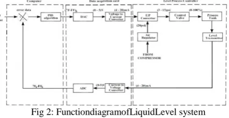
The functional diagram is shown in thefigure2.TheRF capacitance elevel transmitteris usedf ormeasuringtheliquidlevel intheprocesstank.Inlevelcontrolaction,thepumpsucks waterfromreservoirtankandprovidesittocontrolvalve.The errorsignalisgeneratedbythePCandaccordingtothiserror;a control signal is generated and given to the Electro-Pneumatic converter. It controls the flow of the fluid in pipeline by varying stem position of the control valve. For maintaining the level of the process tank, flow is manipulated level signal is given to the Data acquisition card. By pass line is provided to avoid the pump overloading.
Fig 2: FunctiondiagramofLiquidLevel system
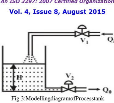
Thecomponentsspecificationoftheplantisgivenin thetable 1.Fordesigningthecontrolparameters,thefirststepisto obtainthemathematicalmodeloftheplant,LLS.Thelinear modellingisexplainedinthissectioninasimplemethod[5]by consideringthe figure3.
Table1:Specificationof Liquid Level System
Pump Process tank Reservoir tank Model Tullu 80 Material Acrylic Material Mild
ISSN (Print) : 2320 – 3765 ISSN (Online): 2278 – 8875
I
nternational
J
ournal of
A
dvanced
R
esearch in
E
lectrical,
E
lectronics and
I
nstrumentation
E
ngineering
(An ISO 3297: 2007 Certified Organization)
Vol. 4, Issue 8, August 2015
Fig 3:ModellingdiagramofProcesstank
Let Qi and Qo are the inflow rate and outflow rate (in m3/sec) of the tank, and H is the height of the liquid level at
any time instant. We assume that the cross sectional area of the tank be A. In a steady state, both Qi and Qo are same, and
the height H of the tank will be constant. But when they are unequal, we can write,
Qi− Qo= A dH
dt
But the outflow rate Qo is dependent on the height of the tank. Considering the Valve V2 as an orifice, considering
that the opening of the orifice (valve V2 position) remains samethroughout the operation, therefore,
Qo= C H
where, C is a constant. So from equation (1) we can write that,
Qi− C H = A
dH dt
The nonlinear nature of the process dynamics is evident from equation 3, due to the presence of the term H. In order to linearize the model and obtain a transfer function between the input and output, let us assume that initially Qi= Qo =
Qs; and the liquid level has attained a steady state value Hs.
Now expanding Q0 in Taylor’s series, we can have
Qo= Qo Hs + Qo Hs H − Hs + ⋯
Taking first order approximation, we obtain linear model as
q = Adh dt+
1 R
whereq= Qi - Qo
h=H – Hs
Hs is the steady stateheight
From(5)thetransfer function ofthe plant is obtained as:
h(s) q(s)=
R τs + 1
where,
R =2 Hs
C
and
τ = R ∗ A
Equation 6 is the transfer function of the plant.
III.FRACTIONAL ORDER PID CONTROLLER
Inthelasttwodecades,fractionalcalculushasbeen redefinedand implementedinmanynumberoffields,mainlyin theareaofcontroltheory[6],[7],[8],[9].Fractionalorder proportional-integral-derivative(FOPID)controllershave receivedaconsiderableattentioninthelastyearsandthey can providemoreflexibilityinthe c o nt r o l fi e l d whe n c o mp a r e d wi t h thestandardPIDcontroller,becausetheyhavefive parameterstotune.Otherthan Kp, Ki, and
Kdcontrolparameters ofnormalPIDcontroller,λandμ,fractionalpowers oftheintegralandderivativeparts,respectivelyadded
(6) (5) (3)
ISSN (Print) : 2320 – 3765 ISSN (Online): 2278 – 8875
I
nternational
J
ournal of
A
dvanced
R
esearch in
E
lectrical,
E
lectronics and
I
nstrumentation
E
ngineering
(An ISO 3297: 2007 Certified Organization)
Vol. 4, Issue 8, August 2015
the better flexibilityofFractional order PID controller.
The differential equation of Fractional order PID controller is given as:
U t = Kpe t + KdJtλe t + KiDtμe(t)
The continuous transfer function of FOPID is also obtained through Laplace transform as:
C s = Kp+
Ki
sλ+ Kdsμ
IV.FRACTIONAL ORDER PID: TUNING
Fractional PID controller is an extended and much more advanced form of PID controller with more number of control parameters increasing the design freedom and controller flexiblity. The tuning is done to obtain the parameters of PID controller Kp, Ki and Kdby Ziegler-Nichols and Astrom-Hagglund method. The integral and differential order, λ
and μ are then obtained by solving the non-linear equations which are obtained by considering the phase margin is equal to the desired phase margin and the criteria
⃒C jωcp G jωcp ⃒ = 1
the equation below must be satisfied:
C jωcp = 1 ⃒G(jω cp)⃒e
j∅pm = K
ccos∅pm + jKcsin∅pm
LHS of the equation can be written as below:
C jωcp = Kp+ Kiωcp−λcos π
2λ + Kdωcp μcos π
2μ +
j[−Kiωcp−λsin
π
2λ + Kdωcp
μsin π
2μ ]
Thus the non-linear equations are obtained as:
f1 λ, µ = kp+ kiωcp−λcos( π
2λ) + kdωcp µcos(π
2µ)-kc(cos∅pm)
f2 λ, µ = −kiωcp−λcos( π
2λ)+kdωcp µsin(π
2µ)-
kc(sin∅pm)
Hence all the control parameters of Fractional order PID controller is obtained.
I.ROBUST FOPID DESIGNING
The Robust FOPID is designed by varying the parameter of the plant. The Liquid Level system modelled is of the form:
G(s) = k
τs+1e −Ls
The parameters are varied and four transfer functions are obtained as:
G1(s) = k τs+1e
−Ls
G2 s = k τs+1e
−Ls
G3 s = k τs+1e
−Ls
G4 s = k τs+1e
−Ls
With this variation in parameters, the Robust Fractional Order PID controller is designed from Monje-Vinagre et al method, where FOPID design algorithm for the system to satisfy five design criteria such as magnitude of gain cross over frequency, phase margin, robustness to plant uncertainties, high-frequency noise attenuation and sensitivity functions as follows:
⃓C(jωcg)G(jωcg)⃓dB = 0dB
(Arg(C(jωcg)G(jωcg)) = −π+∅pm
(d(Arg (C(jωcg)G(jωcg)))
dω )ω=ωcg = 0
⃓T(jω)=(C(jω)G(jω))
1+C(jω)G(jω)⃓dB ≤ A dB
⃓S(jω)= 1
1+C(jω)G(jω)⃓dB ≤ B dB
In order to design Robust FOPID controller, the above conditions are satisfied with G2 satisfying equation 13 and
G4 satisfying equation 14. Equation 15 should be satisfied with transfer function G3, similarly equation 16 and equation
17 by G1 and G2.
Therefore the desired specifications are as follows:
⃓C(jωcg)G2(jωcg)⃓dB = 0dB
(Arg(C(jωcg)G4(jωcg)) = −π+∅pm
(d(Arg (C(jωcg )G4(jωcg)))
dω )ω=ωcg = 0
⃓T(jω)=(C(jω)G1(jω))
1+C(jω)G1(jω)⃓dB ≤ A dB
⃓S(jω)= 1
1+C(jω)G2(jω)⃓dB ≤ B dB
On substituting the transfer functions, the solutions are obtained as:
( k
((T.ωcg)2+1
)( (r)2+ (s)2)
dB
=0dB
a tan s
r − a tan T . ωcg − ωcg. L = −π + ∅pm 1 1+(s/r)2.
(su .r−s.ru ) (r)2 −
T
1+(T.ωcg)2− L = 0
k (rt )2+(st )2
(1+k.rt )2+(T.ω t+k.st )2
dB
≤ −20
(T.ωs)2+1
(1+k.rs )2+(T.ωs+k.ss )2
dB
≤ −20dB
where,
r= kp+ kiωcg−λcos( π
2λ)+kdωcg μcos(π
2μ)
s= -kiωcg−λsin( π
2λ)+kdωcg μsin(π
2μ)
ru = −kiωcg−λ−1cos( π
2λ)+kdωcg
μ−1cos(π 2μ)
su= −kiωcg−λ−1sin( π
2λ)+kdωcg
μ−1sin(π 2μ)
rt= kp+ kiωt−λcos( π
2λ)+kdωt μcos(π
2μ)
st= −kiωt−λsin( π
2λ)+kdωt μsin(π
2μ)
rs= kp+ kiωs−λcos( π
2λ)+kdωs μcos(π
2μ)
ss= −kiωs−λsin( π
2λ)+kdωs μsin(π
2μ)
Solving these equations, the control parameters:Kp, Ki, Kd, λandμ are obtained for the robust stability of the plant. The Bode response is then obtained.
The Robust PID controller is then designed by obtaining the Nominal plant. The Robust PID controller as well as the Robust FOPID controller is then implemented on pert urbed plant and the frequency response of the respective controllers are compared.
(19) (18)
(21) (20)
ISSN (Print) : 2320 – 3765 ISSN (Online): 2278 – 8875
I
nternational
J
ournal of
A
dvanced
R
esearch in
E
lectrical,
E
lectronics and
I
nstrumentation
E
ngineering
(An ISO 3297: 2007 Certified Organization)
Vol. 4, Issue 8, August 2015
A. PROPOSED METHOD
The transfer function of LLS shown in figure 3 is obtained after taking the measurements radius of inlet valve, outlet valve, process tank and undergoing certain calculations. The transfer function of LLS is therefore obtained as:
G(s) = 1.23
0.924𝑠+1𝑒 −1𝑠
which is of first order plus a delay system.
The tuning of FOPID controller for desired phase margin of 30° is as shown in the table 2.
Table 2: Fractionalorder PIDcontrolparameter CONTROL
SCHEME
Kp Ki Kd λ μ
FOPID 1.0440 1.0158 0.63485 0.4433 1.0467 The Robust PID controller is designed by varying the parameters of plant as:
k from 0.98 to 1.8;τ from 0.82 to 1.12; and L from 0.6 to 1.3 The desired phase margin is taken as 40°.
Therefore, the transfer functions G1, G2, G3 and G4 will become:
G1(s) =
0.98 0.82s + 1e
−1.3s
G2 s =
1.8 0.82s + 1e
−1.3s
G3 s =
1.8 0.82s + 1e
−0.6s
G4 s =
0.98 1.2s + 1e
−1.3s
The Robust FOPID controller with the plant variation is obtained by solving equations 18 to 22 and the results are as shown in table 3.
Table 3: Robust Fractionalorder PIDcontrolparameter CONTROL
SCHEME
Kp Ki Kd λ μ
Robust FOPID
0.21288 1.3464 0.78157 0.87253 0.89981 The Frequency response of Robust FOPID controller is shown in figure 5.
A Robust PID controller is designed for with plant parameter variation, by obtaining the nominal plant. The nominal plant is obtained as:
Gn(s) =
1.38 1.1𝑠+1𝑒
−0.8𝑠
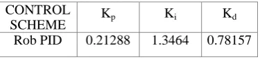
The PID controller for the Nominal plant is designed and the parameters are shown in the table 4. Table 4: Robust PID control parameters
CONTROL
SCHEME Kp Ki Kd Rob PID 0.21288 1.3464 0.78157
The frequency response of the controller is shown in figure 6. The comparison of frequency response of Robust FOPID and Robust PID controller is shown in figure 7. The Robust FOPID and Robust PID controllers are implemented in a perturbed plant for comparing their response. The perturbed plant used for comparison is:
(23)
Gp(s) =
1.411 0.95s+1e
−0.84s
The comparison is as shown in figure 8.
V. SIMULATION RESULTS
The desired phase margin is obtained from the Fractional PID controller designed as shown in figure 4.
Fig 4: FrequencyResponse of proposed controller
The frequency response of Robust FOPID with the plant parameter variation is shown in figure 5.
Fig 5: Frequency Response of Robust FOPID controller
The phase margin requirement is attained by the FOPID controller. The Frequency response of the PID designed for nominal plant is shown in figure 6.
Fig 6: Frequency Response of PID controller on nominal plant
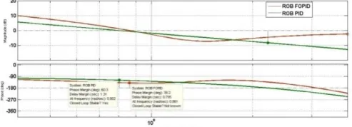
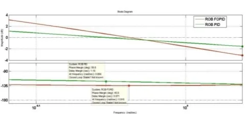
For comparing the Robust FOPID with the PID, the frequency response of both the controllers on nominal plant as well as a perturbed plant is plotted as in figure 7 and figure 8.
Fig 7: Comparing FOPID and PID controllers
ISSN (Print) : 2320 – 3765 ISSN (Online): 2278 – 8875
I
nternational
J
ournal of
A
dvanced
R
esearch in
E
lectrical,
E
lectronics and
I
nstrumentation
E
ngineering
(An ISO 3297: 2007 Certified Organization)
Vol. 4, Issue 8, August 2015
Fig 8: Comparing FOPID and PID on perturbed plant
VI. CONCLUSION
A simple LiquidLevelSystemhasbeenmodelledand t h e Transfer functionisobtainedasinequation13.TheFractionalOrder PIDcontroller design technique has been discussed and implemented in the plantandthe frequencyresponseistakenandhasbeenvalidatedthatthe requiredphasemarginissatisfiedbythecontroller.
The Robust FOPID design technique has also been discussed and implemented on the plant with variations in parameters. The Robust FOPID has met the desired phase margin. The phase angle is remaining constant for the frequency from 0.63 to 1.12. A PID controller for the nominal plant has been designed and its robustness is verified. For the value of frequency from 0.55 to 1, the phase angle is remaining constant.
The controllers have been implemented in nominal plant and the frequency response is compared, and it is observed that in FOPID controller, the phase angle is remaining constant for a wider range than the PID controller. The controllers are also implemented in perturbed plant and the frequency response has been verified and it is noted that the phase angle of FOPID controller remains constant for frequency range of 0.6 to 0.98, but phase angle of PID controller is not constant, therefore, it is clear that FOPID has got more robust performance than PID controller.
REFERENCES
[1] Podlubny I., ‘Fractional-order systems and PIλDμ controllers,’ IEEE Transactions on Automatic Control, volume. 44, issue 1, pages 208-214, 1999.
[2] Irving,E.,Miossec,C.,Tassart,J., ‘Towards efficient full automatic operation of the PWR steam generator with water level adaptive control’ 2nd International Conference on Boiler Dynamics and Control in Nuclear Power Stations ,.British Nuclear Energy Society, Bournemouth, pages.309– 329, 1980.
[3] Bendotti,P.,C.M.FalinowerandJ.M.Legros ‘ Steam GeneratorWaterLevelControl:ABenchmarkfor HybridControl Techniques.’ InternationalFederation of AutomaticControl,Volume16part1,pages333-336, 1999.
[4] C.Yeroglu,N.Tan, ‘ Noteonfractional-order proportional–integral–differential controller design’, IETControlTheoryAppl.,Vol.5,Issue17,pages 1978–1989,2011.
[5] NPTELstudymaterial, Version 2 EE IIT, Kharagpur. [6] RadekMatusu,‘Applicationoffractionalordercalculus
tocontroltheory,’InternationalJournalofMathematicalmodelsandmethodsinappliedsciences,Volume5, Issue7,pages 1162-1169,2011.
[7] QinChangmao,QiNaiming,SongZhiguo,‘Fractional PIDcontrollerdesignofHypersonicFlightVehicle,’in proceedingsofInternationalconferenceonComputer, Mechatronics,ControlandElectronicEngineering (CMCE),pages466-469, 2012.
[8] Y.Luo,H.Chao,L.DiandY.Q.Chen, ‘ Lateral directionalfractionalorder(PI)αcontrolofasmall fixed-wingunmannedaerialvehicles:controllerdesigns andflighttests,’IETControlTheoryApplication, volume 5,issue8,pages2156-2167, 2011.
[9] C.A.monje,Y.Q.Chen,D. Xue, B.M. VinagreandV. Feliu, ‘Fractional order Systems and Control: FundamentalsandApplications’,AdvancesinIndustrialControl, Springer,2010.
[10] Monje, C.A., Vinagre, B.M., Feliu, V., et al.: ‘Tuning and auto-tuning of fractional order controllers for industry applications’, Control Eng. Pract., 2008, 16, pp. 798–812.
[11] Vinagre, B.M., Monje, C.A., Calderon, A.J., Suarez, J.I.: ‘Fractional PID controllers for industry application’, J. Vibr. Control, 2007, 13,(9–10), pp. 1419–1429.