A New Control Strategy for Harmonic
Elimination Using shunt Active Filter
Geethu M. Suresh1, Jancy Varghese2
PG Student [Power Systems], Dept. of EEE, Saintgits College of Engineering, Kottayam, Kerala, India1
Assistant Professor, Dept. of EEE, Saintgits College of Engineering , Kottayam, Kerala, India 2
ABSTRACT:Load compensators are used for reactive power compensation as well as harmonic compensation have the disadvantage of high cost and poor efficiency due to switching losses. So it is good to use active harmonic filters
for harmonic compensation and traditional methods comprising of thyristor-switched capacitors for reactive power compensation. Existing load compensators have the capability to differentiate between the fundamental reactive component and harmonic components of the load currents ,but are complex and so they are not cost effective.In order to overcome this limitation, a shunt harmonic filter, which is capable of compensating only the harmonic components of the load current and having a simple control circuitary is proposed in this paper.
KEYWORDS: Phase Locked Loop, PI (Proportional Integral) Controller, Total Harmonic Distorton(THD), Active Harmonic Filter
I.INTRODUCTION
A shunt load compensator is used for harmonic current requirement of the nonlinear load can additionally provides reactive power support for power factor correction and/or voltage regulation As the load compensator supplies the reactive component of the load current along with harmonics, it is required to be rated to carry the reactive component of the load current also. Moreover, the high bandwidth requirement of the controller which forces the compensator to supply the harmonic component of the load current necessitates the semiconductor switches to operate at high switching frequencies Operation of semiconductor devices at high switching frequency while they carry large current leads to increment in device current rating and switching losses. The increased rating makes the load compensators expensive.
The objective is to overcome this limitation is by providing compensators that act as active harmonic filters (AHFs) to compensate only for the harmonic components of the load current, while traditional methods comprising of thyristor switched capacitors/reactors are used to carry out reactive power compensation of the given load. So the converter of an AHF has to carry only the harmonic components of the load current, its current rating and the incurred power loss are less compared to that of a load compensator.
In this paper, it proposes an efficient and simple control scheme for harmonic elimination using shunt active filter.It is capable of compensating only the harmonic components of the load current .So the losses can be minimized and also the cost.
II.LITERATURE SURVEY
III. METHODOLOGY
Fig 3.1: Schematic Block diagram of single phase Active Harmonic filter systems
Vs and is are respectively the grid voltage and grid current. Vdc is the DC link voltage. L is the series inductor. C is the DC link capacitor. iI is the filter current.T he switching pulses to the semiconductor switches of the filter is generated as shown below.
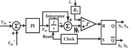
Fig 3.2:Carrier waveform (sawtooth), modulating waveform x, and gating signal
When the modulating signal x (isRs) is less than the sawtooth waveform, S3 and S4 are turned on, thereby making the output voltage of the converter to be –Vdc. When x is greater than the sawtooth waveform, S1 and S2 are turned on, and the output voltage of the converter is +Vdc.
1.Conventional Method
Fig 3.3:Block diagram of the controller for the conventional single-phase load compensator system
2.Existing Control Scheme
Fig 3.4: Block diagram of the controller for existing system
Modulating signal changes to (is-icref)Rs. icref is the reference value of reactive current to be supplied by the source. which is obtained by finding the value of emulated inductance Le .Which is the equivalent inductance of the Parallel combination of the non linear load and the filter. The grid current and grid voltage are not in phase. Also the additional loop makes a phase shift between the fundamental component of the grid current and converter output voltage. Now the burden of supplying the reactive power requirement of the non linear load is on the the grid not on the converter. Fig 3.5 shows the Schematic block diagram of the feedback loop which sets the value of the emulated inductance in existing method.II1 is the fundamental component of filter current.II1peak is the peak value of the fundamental component of filter current.
Fig 3.5: Schematic block diagram of the feedback loop which sets the value of the emulated inductance.
3. Modified Control Scheme
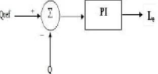
In the new control scheme the circuit used to find the value of emulated inductance is changed. The new control circuit is simple compared to the existing one. Fig 2.6 shows the Schematic block diagram of the feedback loop which sets the value of the emulated inductance in the new control scheme.Q and Qref are respectively the actual and reference value of reactive current to be supplied by the source.
IV. RESULT AND DISCUSSION
Total Harmonic Distortion (THD) of source current and load current for the conventional method,Existing method and modified method are shown below. Comparison of the methods with and without using PI controller are also made.
Fig 4.1: THD of source and load current for conventional method without PI Controller.
Fig 4.1and 4.2 shows respectively the variation in total Harmonic distortion of source current (THD IS) and load current (thd IL) in conventional method with and without using PI controller.
Fig 4.2: THD of source and load current for conventional method with PI Controller.
From Fig 4.1 and 4.2 it is clear that introducing a PI controller can reduce the THD of source current and load current. This is same for the other two methods also.
Fig 4.3: THD of source and load current for existing method without PI Controller.
Fig 4.3and 4.4 shows respectively the variation in total Harmonic distortion of source current (THD IS) and load current (thd IL) in existing method with and without using PI controller.
Fig 4.4: THD of source and load current for existing method with PI Controller.
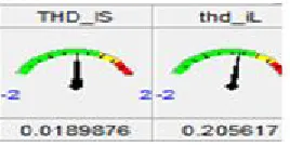
Fig 4.5and 4.6 shows respectively the variation in total Harmonic distortion of source current (THD IS) and load current (thd IL) in new or modified method with and without using PI controller.
Fig 4.6: THD of source and load current for new method with PI Controller.
when comparing Fig 4.4 and 4.6, it is clear that the new method is more capable of reducing the THD of load current and source current than the existing method.
V.CONCLUSION
Conventional load compensators are capable of reactive power compensation along with harmonic compensation so the rating of the converter and thus the cost increases. But the existing load compensators are capable of harmonic compensation alone and thus converter rating is reduced. So it is cost effective. And when we come to the new system, with all the advantages of the existing system, the THD can further be reduced.
REFERENCES
[1] M. Cirrincione, M. Pucci, G. Vitale, and A. Miraoui, “Current harmonic compensation by a single-phase shunt active power filter controlled by adaptive neural filtering”, IEEE Trans. Ind. Electron., vol. 56, no. 8, pp. 3128-3143, 2009.
[2] J. M. Kanieski, R. Cardoso, H. Pinheiro, and H. A. Gründling, “Kalman filter based control system for power quality conditioning devices”, IEEE Trans. Ind. Electron., vol. 60, no. 11, pp. 5214-5227, 2013.
[3] K. M. Smedley, L. Zhou, and C. Qiao, “Unified constant-frequency integration control of active power filters-steady-state and dynamics”, IEEE Trans. Power Electron., vol. 16, no. 3, pp. 428-436, 2001.
[4] Q. Chongming and K. M. Smedley, “Three-phase bipolar mode active power filters”, IEEE Trans. Ind. Appl., vol. 38, no. 1, pp. 149-158,2002. [5] E. S. Sreeraj, K. Chatterjee, and S. Bandyopadhyay, “One cycle controlled single-stage, single-phase voltage sensor-less grid-connected PV
system”, IEEE Trans. Ind. Electron., vol. 60, no. 3, pp. 1216-1224, 2013.
[6] S. Chattopadhyay and V. Ramanarayanan, “Phase-angle balance control for harmonic filtering of a three-phase shunt active filter system”, IEEE Trans. Ind. Appl., vol. 39, no. 2, pp. 565-574, 2003.
[7] K. Chatterjee, D. V. Ghodke, A. Chandra, and K. Al-Haddad, “Modified one cycle controlled load compensator”, IET Power Electron.,vol.4, no. 4, pp. 481-490, 2011.