Analysing Different Modes of Operation of a
Power Conditioner in Improving the Power
Quality of a Distribution Grid
Anju R K1, Fossy Mary Chacko2
PG Student [Power System], Dept. of EEE, Saintgits College of Engineering, Kottayam, Kerala, India1
Assistant Professor, Dept. of EEE, Saintgits College of Engineering, Kottayam, Kerala, India2
ABSTRACT: With the increase in penetration of distributed energy resources (DERs) there is a corresponding increase in power quality problems and intermittencies on the distribution grid. The aim of this paper is to improve the power quality of the distribution grid. The proposed power conditioner has active power capability which is useful in mitigating the grid intermittencies and in improving the voltage sag and swell compensation. Here, an energy storage is integrated into dc-link of the power conditioner through a bidirectional dc-dc converter that helps in providing a stiff dc-link voltage. The integration helps in providing active/reactive power support, intermittency smoothing, sag/swell compensation and harmonic compensation. The power conditioner operates in five different modes, each of which has been analysed. The design and control of both the dc-ac inverters and the dc-dc converter is also developed.
KEYWORDS: Dynamic Voltage Restorer (DVR), Active Power Filter (APF), Distribution Grid (DG), Power Conditioner (PC), Distributed Energy Resource (DER)
I. INTRODUCTION
Power quality is a major cause of concern in the industry and it is important to maintain good power quality on the grid. [1]. Therefore, there is renewed interest in power quality products like the dynamic voltage restorer (DVR) and the active power filter (APF). The topology which resulted after the integration of dynamic voltage restorer (DVR) and active power filter (APF) [2] through a back-back inverter topology was termed as a unified power quality conditioner (UPQC).
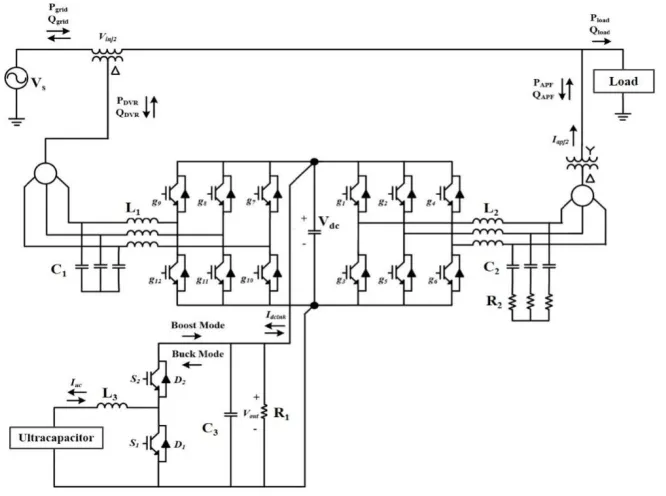
Most of the DERs are intermittent and integrating them with energy storage not only improves the reliability of the DERs but also gives an opportunity to provide additional functionalities such as active and reactive power support and voltage sag/swell compensation to distribution grid. Of all the energy storage technologies ultracapacitors (UCAP) have low energy density and high power density and fast charge/discharge characteristics. Therefore, they are ideally suited for providing support to events on the distribution grid which require high power and low energy for short spans of time. UCAP based energy storage can be integrated into the distribution grid through a bi-directional dc-dc converter and a dc-ac inverter and this integration can be carried out by connecting the dc-ac inverter in series as a Dynamic Voltage Restorer (DVR) or in shunt as an Active Power Filter (APF) with the grid.
II. SYSTEM MODEL
optimum voltage and current compensation of the converter and the line-line voltage, Vab is 208 V.
Fig 1. Model of Power Conditioner with UCAP energy storage
There are various methods to control the 3-phase shunt APF to provide harmonic and reactive power compensation of which the most common approaches are the p-q method and the id-iq method [2, 11] .The id-iq control performs better in
non-sinusoidal and unbalancedconditions when compared to the p-q method, while both methods perform in a similar manner in balanced sinusoidal conditions. In this system, the id-iq method is modified to provide active and reactive
power compensation such that id controls the reactive power and iq controls the active power [14].Once the reference
currents are calculated they are compared with the actual inverter currents and the error is passed through a Fuzzy controller. The DVR control is based on the in-phase compensation method which requires a PLL for estimating θ [15]. Based on the estimated θ, the line-line source voltages are transformed into the d-q domain and the line-neutral components of the source voltage can be estimated using the DVR controller equations.A bidirectional dc-dc converter [6] is required as an interface between the UCAP and the dc-link, since the UCAP voltage varies with the amount of energy discharged, while the dc-link voltage has to be stiff.Average current mode control [4, 13] is used to regulate the output voltage of the bidirectional dc-dc converter in both Buck and Boost modes, while charging and discharging the UCAP bank.
III. MODES OF OPERATION
The proposed power conditioner can operate in five different modes. The different modes of operation are as described below:
1. Active Power Support Mode 2. Reactive Power Support Mode
3. Renewable Intermittency Smoothing Mode 4. Sag/Swell Compensation Mode
1. Active Power Support Mode
In active power support mode, the Power Conditioner must provide active power to the grid. Based on the reference value, Pref, the Power Conditioner supplies the active power. The dc-dc converter will operate in a
bidirectional fashion in both Buck and Boost modes to respond to the active power requests and regulate the dc-link voltage in a stable fashion, while the inverter controller should respond such that the commanded Pref is supplied by
the inverter through current control.
2. Renewable Intermittency Smoothing Mode
In Renewable Intermittency Smoothing Mode, the Power Conditioner must be capable of both supplying and absorbing active power. The dc-dc converter will operatein a bidirectional fashion in both Buck and Boost mode to regulate the dc-link voltage in a stable fashion, while the inverter controller should respond such that the commanded Pref is supplied/absorbed through the inverter current control.
3. Reactive Power Support Mode
In reactive power support mode, the Power Conditioner must provide reactive power to the grid. In this mode, the Power Conditioner does not provide any active power to the grid and even the APF losses are supplied by the grid. Based on the reference Qref, the power conditioner supplies the reactive power.The goal of the dc-dc converter
controller is to regulate the dc-link voltage in a stable fashion, while the inverter controller should respond such that the commanded Qref is supplied by the inverter through current control.
4. Sag/Swell Compensation Mode
In sag/swell compensation mode, the power conditioner prevents the loads from disturbances on the supply-side like voltage sag or voltage swell. These disturbances require short-term energy storage, and in this mode, the dc-dc converter controller regulates the dc-link voltage in a stable fashion during both sag/swell events. It is also required that the dc-dc converter be able to discharge and meet the active power requirements during a voltage sag and to be able absorb active power in a stable fashion during a voltage swell event.
5. Harmonic Compensation
The APF is controlled to eliminate the harmonics caused by non-linear load connected to the network. The controller maintains the THD well within the IEEE-519 standards.
IV. RESULT AND DISCUSSION
Table I. Simulation Parameters
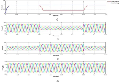
The simulation parameters are as listed in Table I.The system response for a three-phase voltage sag which lasts for 0.1s and has a depth of 0.64pu is illustrated. It can be observed from Figure 3(a) that during voltage sag the source voltage Vsrms is reduced to 0.36pu while the load voltage VLrms is maintained constant at around 1pu due to voltages
injected in-phase by the series inverter. This can also be observed from the plots of the line-line source voltages (Vsab,
Vsbc, Vsca) [Figure 3(b)], the line-line load voltages (VLab, VLbc, VLca) [Figure 3(d)] and the line-neutral injected voltages
of the series inverter (Vinj2a, Vinj2b, Vinj2c) [Figure 3(c)].
a)
a)
b)
c) c)
d)
Parameter Values
Source Voltage 0.208kV Inverter Component IGBT based DC Link Voltage Vdc=260 V
DC Link Capacitor Cdc=3500 µF
Interface Inductor L1=1.25 mH
Inductance L3=0.18 mH
Capacitance C3=66 µF
Load
Three phase non-linear RL load Pload = 1000 W
e)
f)
Fig 3. a) Source and load RMS voltages Vsrms and VLrms during sag b) Source voltages Vsab ,Vsbc , Vsca during sag c)
Injected voltages Vinj2a , Vinj2b, Vinj2c during sag d) Load voltages VLab , VLbc , VLca during sag e)UCAP current f) Active
power of grid, load and inverter during voltage sag
In Figure 3(e) the average UCAP current Iucap increase to provide the active power required by the load during the sag.
It can also be observed from the various active power plots shown in Figure 3(f) where the power supplied to the load Pload remains constant even during the voltage sag when the grid power Pgrid is decreasing. The active power deficit of
the grid is met by the inverter power Pdvr which is almost equal to the input power to the inverter Pdcin available from the
UCAP.Therefore, it can be concluded from the plots that the active power deficit between the grid and load during the voltage sag event is being met by the integrated UCAP-DVR system through the bidirectional dc-dc converter and the inverter.
a)
b)
e)
f)
Fig 4. a) Source and load RMS voltages Vsrms and VLrms during sag b) Source voltages Vsab ,Vsbc , Vsca during sag c)
Injected voltages Vinj2a , Vinj2b, Vinj2c during sag d) Load voltages VLab , VLbc , VLca during sag e)UCAP current f) Active
power of grid, load and inverter during voltage sag
The system response for a three-phase voltage swell which lasts for 0.1s and has a magnitude of 1.2pu is illustrated. It can be observed from Figure 4(a) that during voltage swell the source voltage Vsrms increases to 1.2pu while the load
voltage VLrms is maintained constant at around 1pu due to voltages injected in-phase by the series inverter. This can also
be observed from the plots of the line-line source voltages (Vsab, Vsbc, Vsca) [Figure 4(b)], the line-line load voltages
(VLab, VLbc, VLca) [Figure 4(d)] and the line-neutral injected voltages of the series inverter (Vinj2a, Vinj2b, Vinj2c) [Figure
4(c)].In Figure 4(e) it can be observed that the average UCAP current Iucap change direction to absorb the additional
active power from the grid into the UCAP during the voltage swell event. It can also be observed from the various active power plots [Figure 4(f)] where the power supplied to the load Pload remains constant even during the voltage
swell when the grid power Pgrid is increasing. It can be observed from the inverter power Pdvr and inverter input power
Pdcin plots that the additional active power from the grid is absorbed by the inverter and transmitted to the
UCAP.Therefore, it can be concluded from the plots that the additional active power from the grid during the voltage swell event is being absorbed by the UCAP-DVR systemthrough the bi-directional dc-dc converter and the inverter.
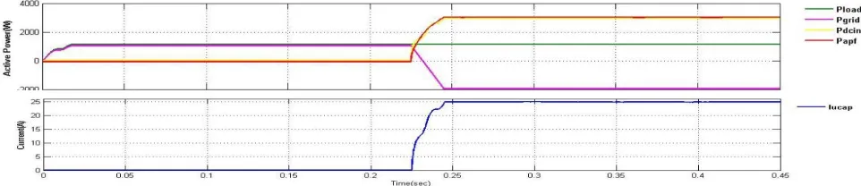
The ability of the system to supply commanded active power is simulated with iqref =-12.0A which translates to Pref of
3054 W. The simulation results are shown in Figure 5(a) and Figure 5(b) where it can be observed that Pinv have
converged to steady state values closely tracking the commanded Pref.
a)
b)
Fig 5. a) Grid, load and inverter active power curves for iqref=-12.0A (active power support) b) UCAP current
The ability of the system to supply the reactive power requirement of the load is simulated with a Qref of 4000Var. The
a)
b)
Fig 6. a) Grid, load and inverter reactive power curves (reactive power support) b) UCAP current
The simulation results for the renewable intermittency smoothing applications where the PC must be capable of both supplying and absorbing active power are illustrated. Since the results for the case where the UCAP and the inverter system supply active power to the grid are already presented in Figure 5 so in Figure 7(a) and Figure 7(b) similar results are presented for the case where the UCAP and inverter system absorb active power from the grid which is achieved by commanding a positive iqref of 7A which corresponds to a Pref of -1782W. It can be observed that Pinv have
converged to steady state values tracking the commanded Pref closely.
a)
b)
Fig 7. a) Grid, load and inverter active power curves for iqref= 7.0A (renewable intermittency smoothing; absorbing active
power) b) UCAP current
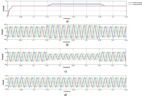
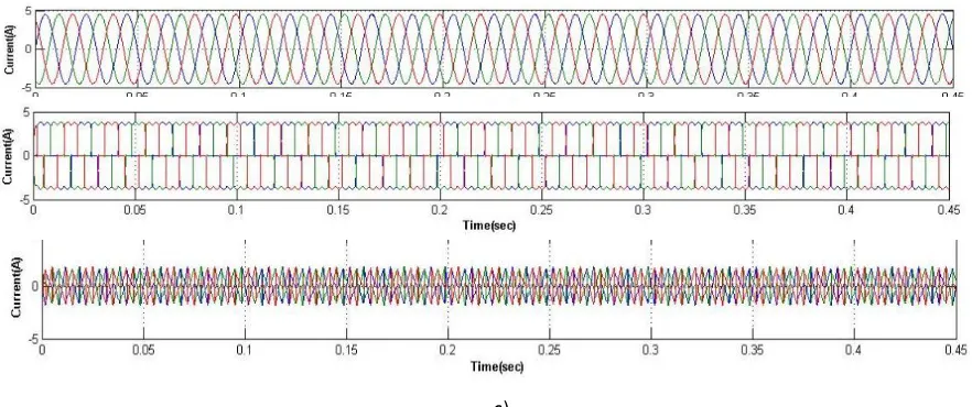
The supply current without Power Conditioner contains harmonic components. With the insertion of Power Conditionerthe THD of the grid current is reduced from 29.15% to 2.64%. Figure 8(a), Figure 8(b) and Figure 8(c)shows the single phase source current, load current and compensating current. The DC link voltage Vdc is
maintained at a constant value of 260V.
a)
b)
Therefore, it is evident from the simulations that the UCAP and APF system can together provide active and reactive power support to the grid. It is also evident that both the dc-dc converter and inverter can operate in a bi-directional fashion which is necessary when the system is used in renewable intermittency smoothing applications. Active power support, reactive power support, renewable intermittency smoothing and harmonic compensation are the primary functionalities the UCAP integrated APF system will be providing to the distribution grid.
V.CONCLUSION
In this paper, the different modes of operation of a power conditioner system to improve the power quality of the distribution grid are presented. With the energy storage integration, the DVR portion of the power conditioner will be able to independently compensate voltage sags and swells and the APF portion of the power conditioner will be able to provide active and reactive power support, renewable intermittency smoothing and harmonic compensation to the distribution grid. UCAP is integrated through a bi-directional dc-dc converter at the dc-link of the power conditioner. The control strategy of the series inverter (DVR) is based on the in-phase compensation and the control strategy of the shunt inverter (APF) is based on the id-iq method. Average current mode control is used to regulate the output voltage
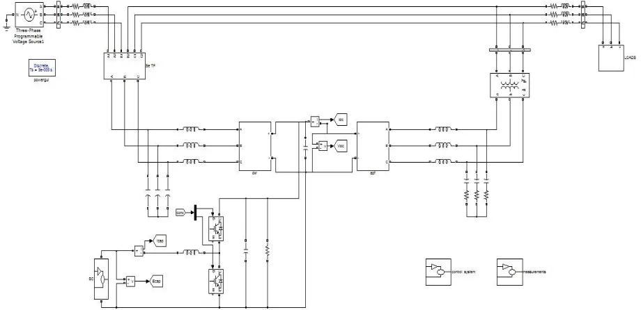
of the dc-dc converter due to its inherently stable characteristic. The simulation of the UCAP-UPQC system is carried out using MATLAB. Results from simulation agree well with the concepts introduced in this paper.
REFERENCES
[1] E.F. Fuchs and M.A.S. Masoum, “Power Quality in Electrical Machines and Power Systems”, Elsevier, Academic Press, USA, Feb. 2008 (ISBN- 13: 978-0-12-369536-9).
[2] V. Soares, P. Verdelho, and G. D. Marques, "An Instantaneous Active and Reactive current component method for active filters," IEEE Trans. Power Electron., vol. 15, no. 4, pp. 660-669, Jul. 2000.
[3] K. Sahay and B. Dwivedi, "Supercapacitors energy storage system for power quality improvement: An overview," J. Energy Sources, vol. 10 , no. 10, pp. 1-8, 2009.
[4] C. Philip, “Modeling average current mode control [of power convertors],” in Proc. IEEE Applied Power Electronics Conference and Exposition, Feb. 2000, pp. 256-262.
[5] P. F. Ribeiro, B. K. Johnson, M. L. Crow, A. Arsoy, and Y. Liu, "Energy storage systems for advanced power applications," Proc. IEEE, vol. 89 , no. 12, pp. 1744- 1756, Dec. 2001.
[6] ArchanaBhat, “Analysis of Ripple Content in DC-DC Converters”, International Journal of Inventive Engineering and Sciences (IJIES) ISSN: 2319–9598, Volume-1, Issue-7, June 2013.
[7] W. Li, G. Joos, and J. Belanger, "Real-time simulation of a wind turbine generator coupled with a battery supercapacitor energy storage system," IEEE Trans. Ind. Electron., vol. 57, no. 4, pp. 1137-1145, Apr. 2010.
[8] S. Bhattacharya, D.M. Divan, T.M. Frank, and B. Banerjee, “Active filter system implementation,” IEEE Ind. Appl. Mag., vol. 4, no. 5, pp. 47–63, Sep./Oct. 1998.
[9] Rejil C, Anzari M, Arun Kumar R, “Design and Simulation of Three Phase Shunt Active Power Filter Using SRF Theory”, Advance in Electronic and Electric Engineering. ISSN 2231-1297, Volume 3, Number 6 (2013), pp. 651-660.
[10] Chennai Salim, Benchouia Mohamed Toufik, “Intelligent Controllers for Shunt Active Filter to Compensate Current Harmonics Based on SRF and SCR Control Strategies”, International Journal on Electrical Engineering and Informatics ‐ Volume 3, Number 3, 2011.
[11] Maria Isabel Milanes Montero, Enrique Romero Cadaval, Fermin Barrero Gonzalez,“ Comparison of Control Strategies for Shunt Active Power Filters in Three-Phase Four-Wire Systems”, IEEE Transactions on Power Electronics, vol. 22, no. 1, January 2007.
[12] K. Wan, J. Liao, and M. Ferdowsi, “Control methods in dc-dc power conversion – a comparative study,” in Proc. Power Electronics Specialists Conference, Jun. 2007,pp. 921-926.
[13] K. Wan and M. Ferdowsi, “Projected Cross Point – a new average current-mode control approach,” in Proc. IEEE Applied Power Electronics Conference and Exposition, Austin, Texas, Feb. 2008.
[14] Deepak Somayajula, Mariesa L. Crow,“An Integrated Active Power Filter–Ultracapacitor Design to Provide Intermittency Smoothing and Reactive Power Support to the Distribution Grid”, IEEETransactions on Sustainable Energy, vol. 5, no. 4, October 2014.
[15] H. Akagi, E. H. Watanabe and M. Aredes, Instantaneous Reactive Power Theory and Applications to Power Conditioning, 1st ed. John Wiley & sons, IEEE Press, 2007.