Antennas and its Techinques
Manshi Bisht ; Lakshmi rajput & Nikhil kumar
Dept. of Electronics& Communication Engineering Dronacharya College of Engg. Farruhknagar , Gurgaon, India
ABSTRACT
Smart antennas are systems attract lot attentions now and believably more in the future, as it can increase the capacity of mobile communication systems dramatically. Design of smart antenna systems combines the technologies of antenna design, signal processing, and hardware implementation. : A smart antenna is therefore a phased or adaptive array that adjusts to the environment. That is, for the adaptive array, the beam pattern changes as the desired user and the interference move; and for the phased array the beam is steered or different beams are selected as the desired user moves. The early smart antenna systems were designed for use in military applications to suppress interfering or jamming signals from the enemy. The proposed research work gives us an overall view of basic smart antennas and its techniques.
KEYWORDS:
Antenna; Miso; Diversity; Beamforming
I. INTRODUCTION
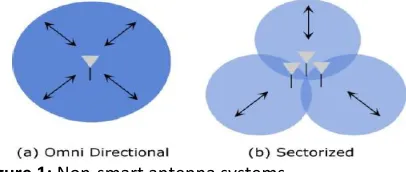
A single antenna element is mostly omni-directional (a). This means it receives and sends in and from all directions around it. If a base station uses an omni-directional antenna and a user communicates with this station, every signal that is send back and forth between the two devices is at the same time a source of interference for any other communication taking place within the same cell.
Figure 1: Non-smart antenna systems
If traffic increases, because devices require higher bandwidth or larger numbers of devices communicate within the same cell, the sources of interference increase equally. This shows the necessity for smart antenna techniques. A simple way of utilizing the availability of multiple antennas is to split the cell into different sectors by using sectorized antennas (b). These kinds of antennas are directional antennas. When positioned correctly on the base station they can be used to subdivide a cell into smaller regions, while the base station still receives signals from all cells. With the use of these antennas (b) the amount of interference is limited to smaller regions instead of the whole cell. Smart antenna techniques however offer a much larger increase in the signal to noise ratio. Already with less complex scenarios than MIMO, such as SIMO or MISO, an important concept of smart antennas can be realized and has been realized for a long time. This concept is called beam forming.
is created. This simulated antenna can then be electrically pointed in a certain direction, without physically moving the “real” antennas . Beam forming can be used in all applications that rely on receiving signals from a certain direction ,whileignoring other signals from the surroundings. Certainly beam forming has its origins in radio technologies and is therefore not a technology that is solely being used in networks. But the principle behind it is extremely able to be used in WMNs, a lot of problems with wireless networks result from environmental or external conditions that interfere with or completely destroy communication paths. Being able to use multiple antennas to “steer” optimized simulated antennas in space to improve sending and reception quality is a powerful method to overcome and adapt to many of these interferences. The range of applications in Wireless Mesh Networks, where nodes have to perform many different tasks simultaneously and adapt to constantly changing surroundings, is easily imaginable.
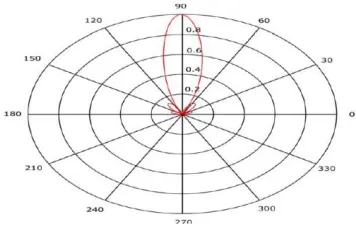
2. ANTENNA RADIATION PATTERNS Every antenna that transmits a signal generates an asymmetrical amount of electromagnetic waves. This amount is always stronger in some directions than in others. This balance and ratio of “field strength” vs.“direction” is called “radiation pattern”. Each part of an antenna radiates these electromagnetic waves with a different amplitude and phase, therefore each of these waves travels a different way. Depending on the construction of the antenna, in some directions there are enough waves traveling a similar distance at similar amplitude, so they can add up and create a “gain”, i.e. a stronger signal or better reception capability. In other directions these waves can absorb each other and create a “loss”, i.e. a weak signal
or no reception capability. This principle is used to create directional antennas. Simply by increasing the size of an antenna the gains and losses can be controlled more effectively, resulting in a narrower, more directed beam.
Figure 2: Three Wavelength Circular Aperture - Field Strength vs. Direction
elements and each connected to the transmitter with identical cables
Figure 3: 7-Element 3λ Linear Array
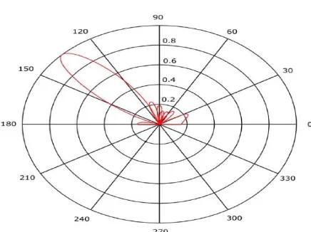
3.STERRED BEAMS and BEAM fORMING If the phases of the individual elements are shifted, the beam points into a different direction, without the antenna having moved or rotated in any way. A simple way to do this would be to alter the length of the cables, connecting the elements to the transmitter. This would result in a phase shift, thus resulting in a beam that is steered to a different direction. Certainly this can be done electronically as well. By programming the transmitter to send out the signal over each of its cables with different delays, an interference in the construction of an antenna becomes unnecessary, and furthermore the steering of the beam can be completely controlled and changed extremely quickly.
Figure 4: 3.5 Wavelength 8 Element Linear Array, Progressive 0.7π Phase Shift
In this way, simple beam forming is done. Additionally to the phase of each antenna
element, also the amplitudes are controlled. By this not only the direction of the beam, but also the sizes of the side lobes and the direction of the nulls can be controlled. With a sufficient amount of array elements, a large number of beams and nulls can be created and steered simultaneously, thus making large antennas extremely efficient. But just by being able to create and steer beams, a network with mobile, moving devices is not yet effectively designed. Beam forming techniques are necessary to program the stations and devices which dispose of multiple antennas. In the scenario of a MISO system, the base station, which is equipped with multiple antennas, could use a beam forming technique to always point the beams towards the direction of arriving signals and point the nulls towards the directions of interfering signals.
Figure 5: Smart antenna techniques – Beamforming
Again, this is easily done in a static network. In a network with mobile devices this becomes more complex. Two of the traditional techniques that are used in MISO scenarios are the “adaptive array” and the “switched-beam” technique. “The adaptive array scheme tracks each user in a given cell with an individual adaptive beam pattern, while the switched-beam scheme selects one beam pattern for each user out of a number of preset fixed beam patterns, depending on the location of the user.”
To achieve an adaptive beam forming a sequence of steps is necessary.
2. The factor for each of these signals has to be continuously controlled.
3. All signals are then combined and output. 4. A decision about the adaptation of the beam is made, based on this output and send back to the weight control.
In comparison to the switched-beam scheme where preset patterns are chosen based on the nature of the received signal, this scheme is considerably more complex. It generally gives better results, but is more expensive to implement and relies on the accuracy of the estimation techniques and the speed of the beam forming algorithms. If applied to the scenario of a Wireless Mesh Network the advantages of adaptive array beam forming over switched beams become more obvious. In a switched beam system a mobile station moves throughout different sectors. The beams do not adapt, they just “switch” to and from one another once a mobile station leaves the coverage of one beam and enters another. In an adaptive array system, not only the beams are directly pointed at the mobile stations, but also the nulls are directly pointed towards the interfering signals. In a Wireless Mesh Network this reduces many problems that may occur due to unexpected interferences. Still a major problem that arises due to overly large amounts of clients in a sector is not satisfyingly solved with adaptive array beam forming only. A third important technique that focuses exactly on this problem of large numbers of clients in multiuser environments is called “opportunistic beam forming”, also referred to as “random beam forming”. For the duration of each transmission a random beam is formed. During a communication training sequences are transmitted back and forth. The mobile station estimates a signal-to-interference-plus-noise-ratio, on which the base station bases a schedule for the specific user traffic. This way time slots are created to make sure the mobile stations can transfer data when
the most effective beams for their position are generated. While offering great advantages in networks with a large amount of mobile stations, in networks with few mobile stations, this technique is not as effective as the previously mentioned more conventional techniques.
4. PLASMA ANTENNA
diversity system; the other is the use of the multiple antennas for the transmission of several parallel data streams to increase the capacity of the system
5. DIVERSITY
Another technique that is used to improve transmission quality and combat the fading of individual channels is diversity. Diversity is used to “exploit the multiple fading paths between the transmitter and the receiver.” This is commonly used in simple SISO scenarios, but with the installation of multiple antennas this diversity can be further exploited on a spatial level. The basic concept of diversity is to transmit the same signal via several independent diversity branches to receive independent signals that can be compared by the receiver. Since there is a high probability that not all the signals fade simultaneously and equally the receiver has several differently faded signals at its disposal and can then reconstruct the original signal much better as if only one signal had been transmitted. Possible diversity dimensions can be time-, frequency, or space-based. Time and frequency diversity have the disadvantage of bringing about a penalty in data rate. Spatial diversity on the other hand can be very effectively used with multiple antennas. In general spatial diversity can be subdivided in the fields of transmit diversity and receive diversity, which indicates that this technique can take place on sender and receiver side. At the receiver side (e.g. in a MISO scenario) the signals could be received over different antenna elements and then be combined following different schemes. Three possible schemes are “selection combining ”, “maximal ratio combining”, and “equal gain combining”, all of which are long established techniques. In selection combining only one of the received signals is chosen. Selected is the channel with the
highest signal-to-noise-ratio. Maximal ratio combining weighs all the signal based on their signal-to-noise-ratio and combines them accordingly. Equal gain combining simply sums up all received signals. If implemented on the transmitter side (e.g. in a SIMO scenario), spatial diversity can also be utilized by sending thesame data over different antennas.
6. CONCULSION
7. REFERENCES
[1] Roos,David.http://communication.ho wstuffworks.com/how-wireless-mesh-networks-work.htm.
[2] Akyildiz, Ian F. and Wang, Xudong. A Survey on Wireless Mesh
Networks. IEEE Communications Magazine.September 2005, Vol. 43, pp. 23-30.
[3] Akyildiz, Ian F. and Wang, Xudong.
Wireless Mesh Networks. s.l. : John Wiley and Sons, 2009. pp. 1, 45-46. [4] Krag, Tomas and Büettrich,
Sebastian. O'Reilly Wireless DevCenter. [Online] January 22, 2004.
http://www.oreillynet.com/lpt/a/4535 .
[5] Gungor, V. C., et al. Challenges and Issues in Designing Architectures and Protocols for Wireless Mesh Networks. [book auth.]
EkramHossain and Kin K. Leung.
Wireless Mesh Networks. s.l. : Springer, 2008, pp. 1-12. [6] Gkelias, A. and Leung, Kin K.
Multiple Antenna Techniques for Wireless Mesh Networks. [book auth.] EkramHossain and Kin K. Leung. Wireless Mesh Networks. s.l. : Springer, 2008, pp. 277-291. [7] Miniwatts Marketing Group. World
Internet Usage Statistics. [Online] March
2009..http://www.internetworldstats. com/stats.htm.
[8] Hu, Honglin, Luo, Jijun and Zhang, Xiaodong. Multiple Antenna
Techniques for Wireless Mesh Networks. [book auth.] Yan Zhang, JijunLuo and Honglin Hu. Wireless Mesh Networking. Architectures, Protocols and Standards. s.l. :Auerbach Publications, 2007, pp. 361-384. 20