ISSN (Print) : 2320 – 3765 ISSN (Online): 2278 – 8875
I
nternational
J
ournal of
A
dvanced
R
esearch in
E
lectrical,
E
lectronics and
I
nstrumentation
E
ngineering
(A High Impact Factor, Monthly, Peer Reviewed Journal)
Website: www.ijareeie.com
Vol. 7, Issue 12, December 2018
A Design of 400 KW Photovoltaic Array
Connected Micro Grid System Using Matlab
Simulink Model
Shweta Dash1, Vishwanath Prasad kumri2
M.Tech Scholar, Dr. C V Raman Institute of Science and Technology, Chhattisgarh, India1
Asst. Professor, Department of E.E.E, Dr. C V Raman Institute of Science and Technology, Chhattisgarh, India2
ABSTRACT: With the development and evolution of modern power system, new challenges appear. This is more apparent in distribution energy systems. The micro grid concept using renewable energy sources is a building block towards the future energy networks for long-term viable solution of energy needs. In a micro grid for example a residential community, a set of distributed energy devices generate and store different types of energy such as electricity and steam to meet time-varying electricity and thermal demand. Micro grid technology has the potential to be an integrated solution that can meet these challenges. The control system is the backbone for the micro grid’s reliable and economic operation. This paper introduces a perspective on 400 kW Micro grid. In addition, the 250 Kw PV array micro grid matlab simulink model is designed in the previous work. We are now designing a 400 kW PV array micro gird matlab simulink model in matlab 2015 version.
KEYWORDS: Matlab /Simulink Model, Micro grid technology
I. INTRODUCTION
Micro grids comprise low voltage distribution systems with distributed energy resources, such as photovoltaic power systems and wind turbines, together with fuel cell and micro turbine. These systems are interconnected to the medium voltage distribution network, but they can be also operated isolated from the main grid. From the customer point of view, microgrids provide both thermal and electricity needs and in addition enhance local reliability, reduce emissions, improve power quality by supporting voltage and reducing voltage dips and potentially lower costs of energy supply. From the utility point of view application of distributed energy sources can potentially reduce the demand for distribution and transmission facilities. Clearly, distributed generation located close to loads will reduce flows in transmission and distribution circuits with two important effects: loss ruction and ability to potentially substitute for network assets. Furthermore, the presence of generation close to demand could increase service quality seen by end customers. Micro grids can provide network support in times of stress by relieving congestions and aiding restoration after faults. The development of micro grids can contribute to the reduction of emissions and the mitigation of climate changes. This is because available and currently developing technologies for distributed generation units are based on renewable sources and micro sources that are characterized by very low emissions. The area of solar energy utilization in the past, present and future; the economics of solar PV energy generation; and, lastly the realization of the renewable generation through subsystem approach such as micro-grid while touching upon the technical issues in the control of converters in micro grids.
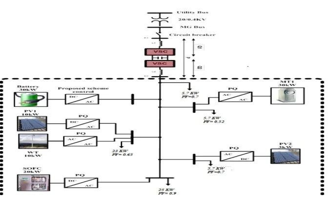
Figure 1.1 single line diagram of the micro grid system
II. MICROGRID CONNECTED PV SYSTEMS
In recent years, however, the number of solar powered homes connected to the local electricity grid has increased dramatically. These Grid Connected PV Systems have solar panels that provide some or even most of their power needs during the day time, while still being connected to the local electrical grid network during the night time. in grid connected PV systems, electricity flows back-and-forth to and from the mains grid according to sunlight conditions and the actual electrical demand at that time. Solar powered PV systems can sometimes produce more electricity than is actually needed or consumed, especially during the long hot summer months. This extra or surplus electricity is either stored in batteries or as in most grid connected PV systems, connected or ―tiedǁ to the local mains electricity grid
ISSN (Print) : 2320 – 3765 ISSN (Online): 2278 – 8875
I
nternational
J
ournal of
A
dvanced
R
esearch in
E
lectrical,
E
lectronics and
I
nstrumentation
E
ngineering
(A High Impact Factor, Monthly, Peer Reviewed Journal)
Website: www.ijareeie.com
Vol. 7, Issue 12, December 2018
III. METHODOLOGY
PROJECT WORK DESCRIPTION
Previous work and foundation of work is desrcibed in our minor project report.In this repport we are going to expain the further work in this regard.
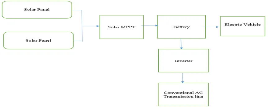
Figure 1.3 Block diagram of Solar powered Micro grid
Nowadays, renewable energy is frequently used of distributed energy sources such as solar power and so on that can be operated in parallel with a wider utility. Nowadays, most of peoples interested to use renewable energy sources such as tidal energy, solar energy, wind energy, geothermal energy, wave energy, and so on. Generation of DC power is done by a micro grid. This block diagram illustrates the storage and utilization of DC power by using a micro grid. These all renewable energy source generates DC power. By generating these DC power we are utilizing by microgrid.
MICRO GRID
A Micro grid is a discrete energy system that consists of distributed energy sources and loads capable of operating in parallel. Thus, the generation, storage and demand management of power becomes easy. The primary purpose is to ensure local, reliable and flexible power for urban and rural communities, at the same time, providing solutions for commercial, industrial and federal government consumers. A microgrid also consists of distributed energy resources like solar PV systems that have several electrical loads
MICRO GRID ARCHITECTURE
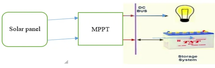
Figure 1.4Micro grid Architecture
Increases the efficiency of energy from the source of generating electricity in accordance to the users’ needs. So very little energy is distribution and transmission. Nowadays with fewer load sources, the demand on the micro grid infrastructure is less than the micro grid. The work describe in which we were going to work is described in the above block diagram. This block represents the solar panel used for required 10 KW capacity micro grid. After that MPPT is connected so that we get maximum energy from solar panel. The battery here use to store the solar energy in form of DC power. The battery is further connected to inverter to supply power to ac transmission line. And battery is can also be directly utilized for other Dc power application. This block diagram describe solar power by interconnecting it to the micro grid that stores and transforms DC power.
IV. RESULT AND DISCUUSION
MODELLING AND SIMULATION OF 400 KW MICRO GRID
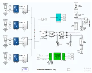
The 400 kW PV array micro grid consists of four PV arrays delivering each a maximum of 100 kW at 1000 W/m2 sun irradiance. A single PV array block consist of 64 parallel strings where each string has 5 Sun Power SPR-315E modules connected in series. Each PV array is connected to a DC/DC converter (average model). The outputs of the boost converters are connected to a common DC bus of 500 V. Each boost is controlled by individual Maximum Power Point Trackers (MPPT). The MPPTs use the "Perturb and Observe" technique to vary the voltage across the terminals of the PV array in order get the maximum possible power.
A three-phase Voltage Source Converter (VSC) converts the 500 V DC to 260 V AC and keeps unity power factor. A 400-kVA 260V/25kV three-phase coupling transformer is used to connect the converter to the grid. The grid model consists of typical 25-kV distribution feeders and 120-kV equivalent transmission system.
In the average model the boost and VSC converters are represented by equivalent voltage sources generating the AC voltage averaged over one cycle of the switching frequency. Such a model does not represent harmonics, but the dynamics resulting from control system and power system interaction is preserved. This model allows using much larger time steps (50 us), resulting in a much faster simulation.
ISSN (Print) : 2320 – 3765 ISSN (Online): 2278 – 8875
I
nternational
J
ournal of
A
dvanced
R
esearch in
E
lectrical,
E
lectronics and
I
nstrumentation
E
ngineering
(A High Impact Factor, Monthly, Peer Reviewed Journal)
Website: www.ijareeie.com
Vol. 7, Issue 12, December 2018
Figure 1.5 Matlab/ Simulink model of 400 kW PV array Micro grid.
SIMULATION WAVEFORM
Start the simulation and see the resulting signals on the various scopes. This three-second simulation allows us to observe the operation of each individual PV Array system under varying irradiances.
Figure 1.7 Output waveform of PV1-(yellow) , PV2-(magenta), PV3-(cyan), PV4-(red)
V. CONCLUSION AND FUTURE SCOPE
The objective of this research work is to design a 400 kW PV array micro grid from PV array to a micro-grid, with Maximum Power Point Tracking capability under all ambient conditions including partial shading conditions. The major conclusions of this research work have been presented. The Matlab / Simulink model of 400 kW PV array connected microgrid is designed in matlab 2015 environment. The simuation wave form shows the VI PQ of the grid. The future work will design of more than 400 kW micro grid.
REFERENCES
[1] B. Shiva Kumar, K. Sudhakar Energy Centre, Maulana Azad National Institute of Technology, Bhopal 462003, MP, India “Performance evaluation of 10 MW grid connected solar photovoltaic power plant in India” 2015
[2] Amit KumarYadavadVikrantSharmabHasmatMalikcS.S.ChandelaDaily array yield prediction of grid-interactive photovoltaic plant using relief
attribute evaluator based Radial Basis Function Neural Network [3] Gridconnected pv array www.mnre.gov.in 2012
[4] Lacour Ayompe, Dublin Institute of Technology Aidan Duffy, Sarah McCormack
Michael Conlon,Measured Performance of a 1.72 kW Rooftop Grid Connected Photovoltaic System in Ireland
[5]Sharma, Vikrant, Chandel, S.S., 2013. Performance analysis of a 190 kW p grid interactive solar photovoltaic power plant in India. Energy 55, 476–485
[6]Ahmad, G.E., Schmid, J., 2001. Feasibility study of brackish water desalination in the Egyptian deserts and rural regions using PV systems. ISESSolar World Congress, 1032–1038.Climate data, 2016. Available at: http://en.climate-data.org/location/957552/. (Cited 2016).EEHC, 2015. Commercial Tariff 2014/2015. EEHC-Egyptian Electrical Holding Company.Elhodeiby,
[7]A.S., Metwally, H.M.B., Farahat, M.A., 2011. Performance analysis of 3.6 kW rooftop grid connected photovoltaic system in Egypt. International Conference on Energy Systems and Technologies (ICEST 2011), Cairo, Egyptian, 2016.
[8]Feed-in Tariff for Wind and Solar PV Projects. IEA-International Energy agency, Available
at:http://www.iea.org/policiesandmeasures/pams/egypt/name-131470-en.php.IRENA, 2013.
[9]Design of Grid Connect PV Systems. Palau Workshop, NorthREP, Available at:http://www.irena.org/DocumentDownloads/events/2013/August/3 design grid connect systems.pdf.Labed, S., Lorenzo, E., 2004.