Efficient Broadcasting with Guaranteed Coverage
in Mobile Ad Hoc Networks
P.Pranitha, G.Swamy , Manjula Aakunuri
Asst Prof,Department of CSE, JITS, Karimnagar, JNTUH, Hyderabad, AP, INDIA
Abstract—In wireless networks comprised of numerous mobile stations, the routing problem of finding paths from a traffic source to a destination through a series of intermediate forwarding nodes is particularly challenging. Some of the current research works cannot fully resolve the void problem, while there exists other schemes that can guarantee the delivery of packets with the excessive consumption of control overhead. The unreachability problem (i.e. the so called void problem) that exists in the greedy routing algorithm in wireless sensor networks. In this paper, a greedy anti void routing (GAR) protocol is proposed to solve the void problem with increased routing efficiency by exploiting the boundary finding technique for the unit disk graph (UDG). The proposed RUT is employed to completely guarantee the delivery of packets from source to destination node under the UDG network. The Boundary Mapping (BM) and Indirect Map Searching (IMS) schemes are proposed as efficient algorithms for the realization of the RUT technique. Comparing with the existing localized routing algorithms the simulation result shows that the proposed GAR based protocols can provide better routing efficiency
Index Terms- Greedy Routing, Void Problem, Localized Algorithms, Wireless Sensor Networks
1. INTRODUCTION
A wireless sensor network (WSN) consists of sensor nodes (SNs) with wireless communication capabilities for specific sensing tasks. Due to the limited available resources, efficient design of localized multihop routing protocols [1] becomes a crucial subject within the WSNs. How to guarantee delivery of packets is considered an important issue for the localized routing algorithms. The well-known greedy forwarding (GF) algorithm [2] is considered a superior scheme with its low routing over- heads. However, the void problem [3], which makes the GF technique unable to find its next closer hop to the destination, will cause the GF algorithm failing to guarantee the delivery of data packets. The network flooding mechanism is adopted within the GRA and PSR schemes while the void problem occurs. There also exist routing protocols that adopt the backtracking method at the occurrence of the network holes (such as GEDIR[4], DFS[5], and SPEED [6]). The routing schemes as proposed by ARP[7] and LFR[8] memorize the routing path after the void problem takes place. Moreover, other routing protocols (such as PAGER, NEAR, DUA, INF, and YAGR) propagate and update the information of the observed void node in order to reduce the probability of encountering the void problem.
Several routing schemes as surveyed in adopt the planar graph derived from the unit disk graph (UDG) as their network topologies. For conducting the above planar graph-based algorithms, the planarization technique is required to
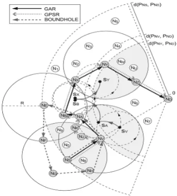
transform the underlying network graph into the planar graph. The Gabriel graph (GG) [9] and the relative neighborhood graph (RNG) [10] are the two commonly used localized planarization techniques that abandon some communication links from the UDG for achieving the planar graph. Nevertheless, the usage of the GG and RNG graphs has significant pitfalls due to the removal of critical communication links, leading to longer routing paths to the destination. As shown in Fig. 1, the nodes (NS,ND) are considered the transmission pair, while NV represents the node that the void problem occurs.
The representative planar graph-based GPSR scheme cannot forward the packets from NV to NA directly since both the GG and the RNG planarization rules abandon the communication link from NV to NA. Considering the GG planarization rule for example, the communication link from NV to NA is discarded since both NJ and NK are located within the forbidden region, which is defined as the smallest disk passing through both NV and NA. Therefore, based on the right-hand rule, the resulting path by adopting the GPSR protocol can be obtained as (NS,NV,NJ ,NK,NA,NB,NX,NY ,NZ,ND). The two unnecessary forwarding nodes NJ and NK are observed, as in Fig. 1.
Fig. 1. Routing paths are constructed using the GAR, the GPSR, and the BOUNDHOLE algorithms for the existence of the void problem.
GAR algorithm without the occurrence of the void problem, while the RUT scheme is served as the remedy for resolving the void problem, leading to the assurance for packet delivery. Moreover, the correctness of the proposed GAR protocol is validated via the given proofs. The implementation of the GAR protocol is also explained, including that for the proposed boundary map (BM) and the indirect map searching (IMS) algorithm for the BM construction.
The performance of the proposed GAR protocol and the version with the enhanced mechanisms (denoted as the GAR-E algorithm) is evaluated via simulations under both the UDG network for the ideal case and the non-UDG setting for realistic scenario. The simulation results show that the GAR-based schemes can both guarantee the delivery of data packets and pertain better routing performance under the UDG network.
II. PROBLEM DEFINATION
Considering a set of SNs N ={Ni │ɏj} within a two- dimensional (2D) Euclidean plane, the locations of the set N, which can be acquired by their own positioning systems, are represented by the set P ={PNi │PNi= (xNi,yNi ),ɏ i }. It
is Considering a set of SNs N ={Ni│ɏj} within a two- dimensional (2D) Euclidean plane, the locations of the set N, which can be acquired by their own positioning systems, are represented by the set P ={PNi│PNi= (xNi ,yNi),ɏ i }. It is assumed that all the SNs are homogeneous and equipped with omnidirectional antennas. The set of closed disks defining the transmission ranges of N is denoted as D ={D(PNi ,R)│ ɏ i },where D(PNi ,R)={x│ǁx-PNiǁ≤ R,ɏ x€ IR2}. It is noted that PNi is the center of the closed disk with R denoted as the radius of the transmission range for each Ni. Therefore, the network model for the WSNs can be represented by a UDG as G(P,E) with the edge set E ={Eij│Eij=(PNi,PNj ),PNi€ D(PNj,R),ɏ i ≠ j. The edge Eij indicates the unidirectional link from PNi to PNj whenever the position PNi is within the closed disk region D (PNj ;R). Moreover, the one-hop neighbor table for each Ni is defined as
Where IDNk represents the designated identification number for Nk. In the GF algorithm, it is assumed that the source node NS is aware of the location of the destination node ND. If NS wants to transmit packets to ND, it will choose the next hop node from its NS which 1) has the shortest Euclidean distance to ND among all the SNs in TNS and 2) is located closer to ND compared to the distance between NS and ND (e.g., NV , as in Fig. 1). The same procedure will be performed by the intermediate nodes (such as NV ) until ND is reached. However, the GF algorithm will be inclined to fail due to the occurrences of voids even though some routing paths exist from NS to ND. The void problem is defined as follows:
Problem 1 (void problem). The GF algorithm is
exploited for packet delivery from NS to ND. The void problem occurs while there exists a void node (NV) in the
network such that no neighbor of NV is closer to the destination as
where d(x, y) represents the Euclidean distance between x and y. TNV is the one-hop neighbor table of NV .
III. GREEDY ANTI-VOID ROUTING (GAR) PROTOCOL
The objective of the GAR protocol is to resolve the void problem such that the packet delivery from NS to ND can be guaranteed. Before diving into the detail formulation of the proposed GAR algorithm, an introductory example is described in order to facilitate the understanding of the GAR protocol. As shown in Fig. 1, the data packets initiated from the source node NS to the destination node ND will arrive in NV based on the GF algorithm. The void problem occurs as NV receives the packets, which leads to the adoption of the RUT scheme as the forwarding strategy of the GAR protocol. A circle is formed by centering at sV with its radius being equal to half of the transmission range R=2. The circle is hinged at NV and starts to conduct counterclockwise rolling until an SN has been encountered by the boundary of the circle, i.e., NA, as in Fig. 1. Consequently, the data packets in NV will be forwarded to the encountered node NA. Subsequently, a new equal-sized circle will be formed, which is centered at sA and hinged at node NA. The counterclockwise rolling procedure will be proceeded in order to select the next hop node, i.e., NB in this case. Similarly, same process will be performed by other intermediate nodes (such as NB and NX) until the node NY is reached, which is considered to have a smaller distance to ND than that of NV to ND. The conventional GF scheme will be resumed at NY for delivering data packets to the destination node ND. As a consequence, the resulting path by adopting the GAR protocol becomes {NS, NV, NA, NB, NX, NY, NZ, ND}.
A. Rolling-Ball UDG Boundary Traversal (RUT) Scheme:
The RUT scheme is adopted to solve the boundary finding problem, and the combination of the GF and the RUT scheme (i.e., the GAR protocol) can resolve the void problem, leading to the guaranteed packet delivery. The definition of boundary and the problem statement are described as follows:
Boundary finding problem: Given a UDG G(P,E) and the
one-hop neighbor tables T={TNi│ɏ Ni€ N},how can a
boundary be obtained by exploiting the distributed computing techniques? There are three phases within the RUT scheme, including the initialization, the boundary traversal, and the termination phases.
1) Initialization Phase
Rolling Ball: Given Ni€ N, a rolling ball RBNi(si, R,/2) is
defined by 1) a rolling circle hinged at PNi with its center point at si€ IR2 and the radius equal to R/2, and 2) there does not exist any Nk€ N located inside the rolling ball as
(RB Ni (si,R/2) N} = Ø, where RB Ni ðsi;R=2Þ de- notes the open disk within the rolling ball.
Starting point: The SP of Ni within the RUT scheme the
center point si€ IR2 of RBNi(si,R/2).
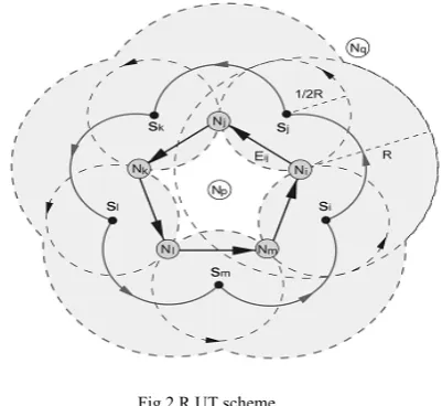
Fig.2.R UT scheme.
Starting point: The SP of Ni within the RUT scheme the center point si€ IR2 of R BNi (si, R,/2). In Fig. 2, each node Ni can verify if there exists an SP since the rolling ball RBNi (si, R,/2) is bounded by the transmission range of Ni. According to the SPs should be located on the circle centered at PNi with a radius of R/2. As will be proven in Lemmas 1 and 2, all the SPs will result in the red solid flower-shaped arcs, as in Fig. 2. It is noticed that there should always exist an SP, while the void problem occurs within the network.
2) Boundary Traversal Phase
Given si as the SP associated with its RBNi(si,R,/2)hinged at Ni, either the counterclockwise or clockwise rolling direction can be utilized. As shown in Fig. 2RBNi (si, R,/2) is rolled counterclockwise until the next SN is reached (i.e., Njin Fig. 2). The unidirectional edge Eij=(PNi,PNj) can therefore be constructed. A new SP and the corresponding rolling ball hinged at Nj(i.e., sj and RBNi (si, R,/2)) will be assigned, and consequently, the same procedure can be conducted continuously.
3) Termination Phase
The termination condition for the RUT scheme happens while the first unidirectional edge is revisited. As shown in Fig. 2, the RUT scheme will be terminated if the edge Eij is visited again after the edges Eij, Ejk, Ekl, Elm, and Emi are traversed. The boundary set initiated from Ni can therefore be obtained as B ={Ni,Nj,Nk,Nl,Nm}.
B. Description of Proposed GAR Protocol:
As shown in Fig. 1, the packets are intended to be delivered from NS to ND. NS will select NV as the next hop node by adopting the GF algorithm. However, the void problem prohibits NV to continue utilizing the same GF algorithm for packet forwarding. The RUT scheme is therefore employed by assigning an SP (i.e., sV ) associated with the rolling ball RBNV (sV ,R/2) hinged at NV . As
illustrated in Fig. 1, sV can be chosen to locate on the connecting line between NV and ND with R/2away from NV. The GF algorithm is resumed at NY , and the next hop node will be selected as NZ. The route from NS to ND can therefore be constructed for packet delivery. Moreover, if there does not exist a node NY such that d(PNY ;PND )<d(PNV ;PND) within the boundary traversal phase, the RUT scheme will be terminated after revisiting the edge EVA. The result indicates that there does not exist a routing path between NS and ND.
C. Proof of Correctness
In this section, the correctness of the RUT scheme is proven in order to solve Problem 2, while the GAR protocol is also proven for resolving the void problem (i.e., Problem 1) in order to guarantee packet delivery.
Lemma 1. All the SPs within the RUT scheme form the
border of a shape that results from overlapping the closed disks D(PNi,R/2) for all Ni€ N, and vice versa.
Proof: Based on Definitions 2 and 3, the set of SPs can
be obtained as S=R1 ɅR2 ={si││si-PNi││ =R/2,ᴟ Ni€ N,si€ IR2 }Ʌ{sj││sj-PNj││ ≥R/2,ɏNj€ N sj€ IR2} by adopting the 1) and 2) rules within Definition 2. On the other hand, the border of the resulting shape from the overlapped closed disks D{PNi ,R/2} for all Ni € N can be denoted as Ω=Q1- Q2 =UNi€N C(PNi ,R/2)- NU Ni€ND(PNi ,R/2) where C(PNi,R/2)and D(PNi, R/2)represent the circle and the open disk centered at PNi with a radius of R/2, respectively. It is obvious to notice that R1 = Q1 and R2 = Q 2, which result in S=Ω .It completes the proof.
Lemma 2. A simple closed curve is formed by the trajectory
of the SPs.
Proof. Based on Lemma 1, the trajectory of the SPs
forms the border of the overlapped closed disks D(PNi,R/2) for all Ni € N. Moreover, the border of a closed filled 2D geometry is a simple closed curve. Therefore, a simple closed curve is constructed by the trajectory of the SPs, e.g., the solid flower-shaped closed curve, as in Fig. 2. It completes the proof.
Theorem 1. The boundary finding problem (Problem 2) is resolved by the RUT scheme.
Proof: Based on Lemma 2, the RUT scheme can draw
simple closed curve by rotating the rolling balls RBNi(si,R/2) hinged at PNi for all Ni €N. The closed curve can be divided into arc segments S(si,sj),where siis the starting SP associated with Ni, and sj is the anchor point while rotating the RBNi (si,R/2) hinged at PNi. The arc segments S (si; sj) can be mapped into the unidirectional edges for all Ni , Nj€ U where U N. Due to the one -to -one mapping between S(Si, Sj) and Eij a simple unidirectional ring is constructed by Eij for all Ni, Nj€ U.Theorem 2.The
void problem (Problem 1) in UDGs is solved by the GAR protocol with guaranteed packet delivery.
Proof. With the existence of the void problem occurred
hinged at NV . The RUT scheme within the GAR protocol will conduct boundary (i.e., the set B) traversal under the condition that d(PNi,PND)≥ d(PNV ,PND )for all Ni€B. Boundary within the underlying network is completely traveled based on Theorem 1, it indicates that the SNs inside the boundary (e.g., NV )are not capable of communicating with those located outside of the boundary (e.g., ND). The result shows that there does not exist a route from the void node (NV) to the destination node (ND), i.e., the existence of network partition. On the other hand, if there exists a node NY such that d(PNY,PND) < d(PNV ,PND ) (as shown in Fig. 1), the GF algorithm will be adopted within the GAR protocol to conduct data delivery toward the destination node ND. Therefore, the GAR protocol solves the void problem with guaranteed packet delivery, which completes the proof.
IV. REALIZATION of GAR PROTOCOL
The implementation of the proposed GAR protocol is explained in this section. The format of the one-hop neighbor table TNi , as defined in (1), is realized for the implementation purpose. TNi is considered a major information source the localized routing protocols, which can be obtained via the neighbor information acquisition [29]. It is noticed that the one-hop neighbor for packet transmission.
A. Implementation of GF Scheme
The GF scheme is considered a straightforward algorithm that only requires the implement ation of the one-hop neighbor table TNi. The next hop node can be found by the linear search of TNiif the void problem does not occur;
B. Implementation of RUT Scheme
1) Concept of Boundary Map
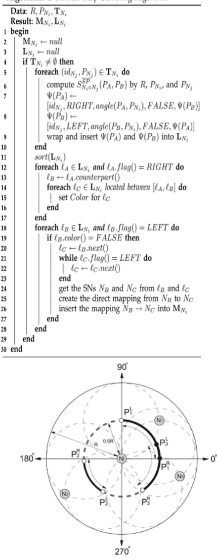
A new parameter called BM (denoted as MNi for each Ni) is introduced in this section. Moreover, the BM MNi is mainly derived from the one-hop neighbor table TNi via the IMS method, as shown in Algorithm 1. Instead of diving into the IMS algorithm, the functionality of MNi is first explained. The purpose of the BM MNi is to provide a set of direct mappings between the input SNs and their corresponding output SNs with respect to Ni. Based on Theorem 1, the two adjacent communication links formed by the input node, the node Ni, and the corresponding output node within the RUT scheme consist part of the network boundary. Therefore, the direct mappings between the input SNs and their corresponding output SNs with respect to Ni lead to the so called BM. An example is shown in Fig. 3 to illustrate the functionality of MNi. Based on Definition 2, the rolling balls hinged at Ni can be constructed by rotating the dashed circle counterclockwise from N1 to N2. The SPs associated with the rolling balls (from Definition 3) result in the arc segment SSPNi(PL1 ;PR2) between the endpoints PL1 and PR2 ,i.e., the dashed arc segment, as in Fig. 3. Similarly, the arc segment SSPNi(PL
2 ;PR3) can be constructed by rotating the rolling balls (hinged at Ni) counterclockwise from N2 to N3.
Fig. 3. Shows the SP and non SP arc segments with respect to Niand the resulting BM.
Definition 4 (SP and non-SP arc segments).Given an
SNNi € N and a pair of points (PA, PB) on the circle (centered at PNi with a radius of R/2), an SP arc segment SSPNi(PA,PB) ofNi is defined by the arc from PA to PB counterclockwise where all points on this arc segment are SPs. Likewise, a non-SP arc segment SSPNi(PA,PB ) of Ni is defined by the endpoint excluding arc from PA to PB counter clockwise, where all points on this arc segment are not SPs.
Definition 5 (converged SP and non-SP arc segments).Given an SP arc segment SSPNi(PA,PB), it is
regarded as a converged SP arc segment if there does not exist any SP arc segment SSPNi(PJ,PK) such that SSPNi(PA,PB) SSPNi(PJ,PK).Similarly, a non-SP arc segment SSPNi(PA,PB) is considered as a converged non-SParc segment if there exists no other non-SP arc segment SSPNi(PJ ,PK) such that SSPNi(PA,PB) SSPNi(PJ ;PK).
It is noticed that the converged arc segments are defined to represent the combined arc segments, e.g., the converged non-SP arc segment SSPNi(PR3 ,PL1) is formed by overlapping the non-SP segments SSPNi(PR3 ,PL
3 ) and SSPNi(PR1 ,PL1),as shown in Fig. 3. As will be proven in Theorem 3, all incoming packets to Ni that are acquired from its neighbor node N1 (which induces the rightmost endpoint PL
1 of the converged SP arc segment SSPNi(PL1 ;PR2)will be forwarded to its neighbor node N2 (which results in the leftmost endpointPR2 of the same converged SP arc segment) under the counterclockwise rolling direction. There exist two converged SP arc segments SSPNi(PL1 ;PR2) and SSPNi(PL2 ;PR3) , where SSPNi(PL1 ;PR2 ) is constructed by the input SN N1 and the corresponding output SN N2 and SSPNi(PL2 ,PR3) is established by the input N2 and the output N3. As a result, the BM with respect to Ni can be obtained as MNi={(N1→ N2),(N2→ N3)}. Therefore, all packets from N1 will be forwarded to N2, while those fromN2 will be relayed to N3 according to the BM.
2) Construction of Boundary Map
Definition 6 (neighbor-related non-SP arc segment).
Anon-SP arc segment SSP Ni (PA,PB ) of Ni is given. If there exists Nj€ N as a neighbor node of Ni such that an arc segment of C(PNi,R/2) that lies inside the closed disk D(PNj,R/2) is identical to SSPNi(PA,PB), this segment SSPNi(PA,PB) is called a neighbor-related non-SP arc segment SSPNioNj(PA,PB),distinguished by Nj.Two properties that are related to the SP and non-SP arc segments are described as follows:
Property 1. The circle C(PNi,R/2) centered at PNi with a
radius of R/2 is entirely composed by all the converged SP and non-SP arc segments of Ni.
Proof. Based on Definitions 2 and 3, it can be observed
that each point on the circle C(PNi,R/2) must either be an SPor a non-SP. A number of adjacent SPs on C(PNi,R/2)will establish an SP arc segment with respect to Ni; while there must exist the largest number of adjacent SPs such that the underlying SP arc segment is a converged SP arc segments with respect to Ni. Therefore, all the adjacent SPs on C(PNi,R/2) will result in converged SP arc segments with respect to Ni. Similarly, all the adjacent on-SPs on C(PNi,R/2) must be aggregated into converged non-SP arc segments with respect to Ni. On the other hand, the circle C(PNi,R/2) is entirely composed by the SPs and non-SPs corresponding to Ni. Consequently, all the converged SP and non-SP arc segments of Ni will construct the entire circle C(PNi;R/2).
Property 2. The union of all the neighbor-related non-SP
arc segments with respect to Ni is equivalent to the union of all the converged non-SP arc segments with respect to Ni.
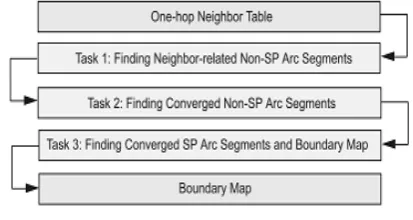
Fig. 4. The process flow of the IMS algorithm
Proof. This property will be proven by contradiction as
follows: It is assumed that the union of all the neighbor related non-SP arc segments corresponding to Ni is not equivalent to the union of all the converged non-SP arc segments with respect to Ni. Based on Definitions 4 and 5,and Property 1, it is stated that all the converged non-SP arc segments with respect to Ni result in the union of all the non-SPs on C(PNi,R/2). Therefore, there must exist anon-SP PJ located on C(PNi,R/2) such that it does not relate to any neighbor-related non-SP arc segments with respect to Ni, i.e., there does not exist any Nk 2 TNithatlies inside the rolling ball RBNi(PJ ,R/2). However, based on Definitions 2 and 3, there should exist at least a node Nk within the rolling ball RBNi(PJ ,R/2) since PJ is a non-SP on C(PN,R/2).Table 1 summarizes the notations in the IMS algorithm, and the pseudo code of the IMS method, as shown in Algorithm 1, is explained as follows: Based on that in Fig. 4,the first task within the IMS algorithm is to identify each neighbor-related non-SP arc segment SSPNiNj(PA;PB) with respect to Ni that is distinguished by its neighbor Nj. Intuitively, it is feasible to utilize the two endpoints PA and PB to represent SSP
Ni Nj(PA;PB), where each endpoint Pfor 2€ {A,B} can be characterized by an
endpoint entry defined as
TATBL I
NOTATION FOR IMS ALGORITHM
endpoint PB is indicated as LEFT). The Angle field is adopted to represent the polar angle with respect to Ni by rotating counterclockwise from the x-axis. The Color field is employed to indicate whether the endpoint Pis a non-SPor not (i.e., Color = TRUE denotes that Pis a non-SP). The Counterpart field provides the linkage to the counterpart endpoint entry that possesses the opposite Flag value (e.g.,the counterpart ofΨNi(PA)isΨNi(PB), and vice versa).Therefore, the neighbor-related non-SP arc segment SSP
Ni Nj(PA;PB) can be denoted by a pair of the endpoint entries as ΨNi(PA),ΨNi(PB)
C. Proof of Correctness
Theorem 3. Given a converged SP arc segment SSPNi(PS,PT)with respect to Ni, where 1) the rightmost endpoint PS is an SP for both Ni and its neighbor NS, and 2) the leftmost endpoint PT is an SP for both Ni and its neighbor NT ,respectively. All incoming packets to Ni that are acquired from its neighbor node NS will be forwarded to NT.
Proof. Based on Definitions 4 and 5, a converged SP arc
segment SSpNi(PS,PT ) is an arc segment composed by some of the SPs with respect to Ni. According to Lemma 2, a simple closed curve is constructed by the trajectory of the SPs. In order to form the closed curve, there must exist other converged SP arc segments contributed by other SNs that are connected to the endpoints PS and PT . In other words, the endpoints PS and PT must also be owned by one of Ni’s neighbor, respectively. On the contrary, the other
points on this converged SP arc segment SSPNi(PS,PT) should
only be contributed by Ni based on Definitions 2 and 3. Moreover, it is intuitive to observe (from Definition 3) that the distances between the SNs related to the same endpoints (i.e., either PS or PT) must be located in their transmission ranges. By adopting the RUT scheme (as stated in Theorems 1 and 2) starting from NS, the rolling ball will be traversed counterclockwise via Ni to NT .This corresponds to the situation that all the packets coming from NS to Ni will be forwarded to NT .It completes the proof.
V. CONCLUSION
In this paper, a UDG-based GAR protocol is proposed to resolve the void problem incurred by the conventional GF algorithm. The RUT scheme is adopted within the GAR
protocol to solve the boundary finding problem, which results in guaranteed delivery of data packets under the UDG networks. The BM and the IMS are also proposed to conquer the computational problem of the rolling mechanism in the RUT scheme, forming the direct mappings between the input/output nodes. The correctness of the RUT scheme and the GAR algorithm is properly proven. The performance of the GAR protocols is evaluated and compared with existing localized routing algorithms via simulations. The simulation study shows that the proposed GAR algorithms can guarantee the delivery of data packets under the UDG network.
REFERENCES
[1]D. Estrin, R. Govindan, J. Heidemann, and S. Kumar, “Next Century Challenges: Scalable Coordination in Sensor Networks, ”Proc. ACM Mobi Com, pp. 263-270, Aug. 1999.
[2] G.G. Finn, “Routing and Addressing Problems in Large metropolitan-Scale Internetworks,” Technical Report ISI/RR-87-180, Information Sciences Inst., Mar. 1987.
[3] B. Karp and H.T. Kung, “GPSR: Greedy Perimeter Stateless Routing for Wireless Networks,” Proc. ACM Mobi Com, pp. 243-254, Aug. 2000.
[4] I. Stojmenovic and X. Lin, “Loop-Free Hybrid Single-Path/Flooding Routing Algorithms with Guaranteed Delivery for Wireless Networks,” IEEE Trans. Parallel and Distributed Systems, vol. 12, no. 10, pp. 1023-1032, Oct. 2001.
[5] I. Stojmenovic, M. Russell, and B. Vukojevic, “Depth First Search and Location Based Localized Routing and QoS Routing in Wireless Networks,” Proc. IEEE Int’l Conf. Parallel Processing (ICPP ’00), pp. 173-180, Aug. 2000.
[6]T. He, J.A. Stankovic, C. Lu, and T. Abdelzaher, “SPEED: A Stateless Protocol for Real-Time Communication in Sensor Networks,” Proc. Int’l Conf. Distributed Computing Systems (ICDCS ’03),pp. 46-55, May 2003.
[7] V.C. Girukaand M.Singhal, “Angular Routing Protocol for Mobile Ad Hoc Networks,” Proc. IEEE Int’l Conf. Distributed Computing Systems Workshops (ICDCSW ’05), pp. 551-557, June 2005.
[8] W.J. Liu and K.T. Feng, “Largest Forwarding Region Routing Protocol for Mobile Ad Hoc Networks,” Proc. IEEE Global Comm. Conf. (GLOBECOM ’06), pp. 1-5, Nov. 2006.
[9] K.R. Gabriel and R.R. Sokal, “A New Statistical Approach to Geographic Variation Analysis,” Systematic Zoology, vol. 18, no. 3,pp. 259-278, Sept. 1969.
[10] G.T. Toussaint, “The Relative Neighborhood Graph of a Finite Planar Set,” Pattern Recognition, vol. 12, no. 4, pp. 261-268, 1980.[23] Q. Fang, J. Gao, and L. Guibas, “Locating and Bypassing Routing Holes in Sensor Networks,” Proc. IEEE INFOCOM ’04,pp. 2458-2468, Mar. 2004